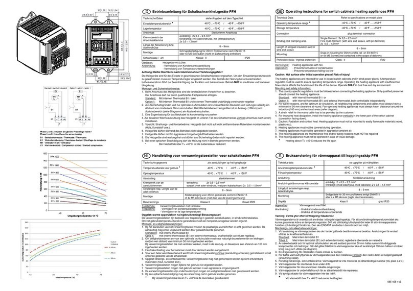
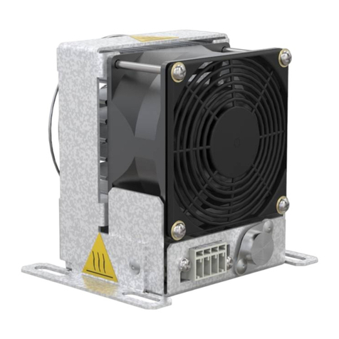
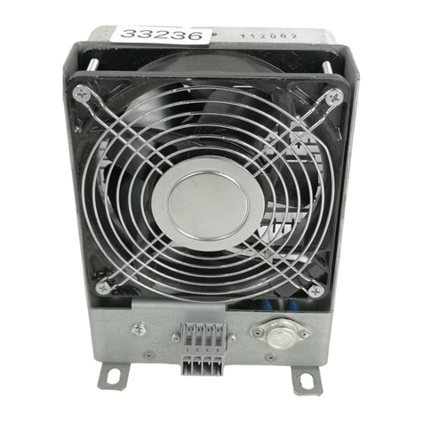
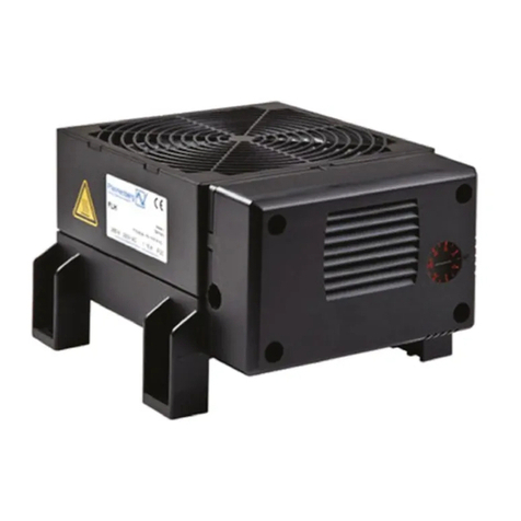
Pfannenberg PFH User manual

085 408 142c
D
Betriebsanleitung für Schaltschrankheizgeräte
PFH/PFH-T
Technische Daten
siehe Angaben auf dem Typschild
Einsatztemperaturbereich *
Einstellbereiche
-40°C ... +70°C / -40°F ... +158°F
-20°C ... +40°C / -5°F ... +105°F
Lagertemperatur
-40°C ... +70°C / -40°F ... +158°F
Schalttemperaturdifferenz /
Schaltpunkttoleranz
< 7K / +/- 4K
Anschluss
Steckklemm-Anschluss
Klemmbereich der
Anschlussklemme
eindrahtig: 2x0,5-2,5mm²
feindrahtig: mit Aderendhülse ohne Kunststoffkragen max. 1mm²
mit Stiftkabelschuh max. 1,5mm²
Länge der Abisolierung bzw.
Aderendhülse
8 – 9mm
Montage
Schnappbefestigung für 35mm Profilschiene nach EN 60715
oder 4x M5 Schrauben (nicht im Lieferumfang enthalten)
Schutzklasse / -art
Klasse: II
IP20
Geräteart: Heizgeräte mit Lüfter.
Anwendung: - Vermeidung von Kondensatwasserbildung
- Vermeidung von Temperaturunterschreitungen
Achtung: Heiße Oberfläche nach Inbetriebnahme! Verletzungsgefahr!
Die Heizgeräte sind für den Einsatz in geschlossenen Schaltschränken vorgesehen. Um den Einsatztemperaturbereich
zu gewährleisten muss ein Temperaturregler eingesetzt werden. Der Betrieb der Heizung bei unzureichendem
Luftvolumenstrom führt zur Beeinträchtigung der Funktion und Lebensdauer. Betrieb NUR in staubfreier und trockener
Umgebung.
Montage- und Sicherheitshinweise:
1. Beim Anschluss des Heizgerätes sind die landesüblichen Vorschriften zu beachten.
Der Anschluss darf nur durch qualifiziertes Fachpersonal erfolgen.
Standard: Mit internen Thermostat B1 / oder
Option 1: Mit internen Thermostat B1 und externen Thermostat unabhängig voneinander regelbar
2. Aus Sicherheitsgründen und zur optimalen Luftzirkulation ist zu benachbarten Bauteilen und Leitungen allseitig ein
Abstand von mindestens 50mm einzuhalten. Bei Lüfter betriebenen Heizgeräten ist im Ansaug- (100mm) und
Ausblasbereich (siehe Diagramm) ein Abstand einzuhalten.
3. Eine Zugentlastung für das Netzkabel ist kundenseitig vorzusehen
4. Zur besseren Wärmeausnutzung das Heizgerät im unteren Teil des Schaltschrankes vertikal (Anschluss nach unten)
installieren.
5. Vorsicht: Strahlungs- und Kontaktwärme: Heizgerät darf nicht auf leicht entflammbaren Materialien montiert werden
(Holz, Kunststoff usw.).
6. Heizgeräte dürfen während des Betriebes nicht abgedeckt werden.
7. Heizgeräte dürfen nicht in aggressiver Umgebungsluft betrieben werden.
8. Die Heizgeräte sind wartungsfrei und dürfen aus Sicherheitsgründen nicht repariert werden.
9. Bei einer optischen Beschädigung darf die Heizung nicht in Betrieb genommen werden.
* Bei Heizbetrieb über T> +40°C ist die Lebensdauer reduziert
GB
Operating instructions for switch cabinets heating appliances
PFH/PFH-T
Technical Data
Refer to specifications on model plate
Operating temperature range *
Setting ranges
-40°C ...+70°C / -40°F … +158°F
-20°C ... +40°C / -5°F ... +105°F
Storage temperature
-40°C ...+70°C / -40°F … +158°F
Temperature difference /
Tolerance for switching point
< 7K / +/- 4K
Connection
plug terminal -connection
Binding post clamping area
Single filament: 2x 0,5 – 2,5 mm²
Fine multi-filament: with wire end sleeve without plastic collar max. 1mm²
with pin terminal max. 1,5mm²
Length of stripped insulation and/or
wire end sleeve
8 – 9mm
Mounting
Snap-in mounting for 35mm profile rail on EN 60715
or 4x M5 Screws (not contained in the scope of delivery)
Protection class / Ingress protection
Class: II
IP20
Device type: Heating appliances with fan.
Application: - Prevents formation of condensation
- Prevents temperature falling too low
Caution: Hot surface after initial operation phase! Risk of injury!
The heating appliances are intended for use in closed switch cabinets and in wind-power plants. A temperature
regulator must be used to ensure operating temperature range. Operating the heating appliance with insufficient air
flow volume affects the function and the life of the device. Operate ONLY in dust free and dry environment.
Mounting and safety information:
1. The country-specific regulations must be followed when connecting the heating appliance. Only qualified personnel
should connect the heating appliance.
Standard: with internal thermostat B1 / or
Option 1: with internal thermostat (B1) and external thermostat, both controllable independently
2. For safety reasons, and for optimum air circulation, all neighboring components and cables must always have a
minimum of 50 mm clearance all-round. Fan-operated heating appliances must always have clearance around the
induction (100 mm) and exhaust areas (refer diagram).
3. A strain relief for the main cable has to be provided by the customer.
4. For improved heat dissipation, install the heating appliance vertically in the lower part of the switch cabinet
(connection facing down).
5. Caution: Radiation and contact heat: Heating appliance must not be mounted to easily flammable materials (wood,
plastic etc.).
6. Heating appliances must not be covered during operation.
7. Heating appliances must not be operated in aggressive ambient air.
8. The heating appliances are maintenance-free and for safety reasons must NOT be repaired
9. The heating appliance must not be operated in case of visual damage.
* Heating above T> +40°C reduces the life span
NL
Handleidi
ng voor verwarmingstoestellen voor schakelkasten PFH/PFH-T
Technische gegevens zie aanduidingen op het typeplaatje
Temperatuurbereik voor gebruik *
instelbereik
-40°C ... +70°C / -40°F ... +158°F
-20°C ... +40°C / -5°F ... +105°F
Opslagtemperatuur
-40°C ... +70°C / -40°F ... +158°F
Schakeltemperatuurverschil /
Schakelpunttollerantie
< 7K / +/- 4K
Aansluiting
steekklemmen
Klembereik van de aansluitklemmen eenaderig: 2x 0,5 – 2,5 mm²
soepel: met ader–eindhuls zonder kunststof kraag max. 1mm²
met pen–kabelschoen max. 1,5mm²
Striplengte resp. Lengte van de ader–eindhuls
8 – 9mm
Montage
Klikbevestiging voor 35mm profielrails conform EN 60715
of 4x M5 schroeven (niet deel van de leveringsomvang)
Beschermings
Klasse II
Graad IP20
Toesteltype: Verwarmingstoestellen met ventilator.
Toepassing: - Vermijden van condensatiewatervorming
- Vermijden van te lage temperaturen
Opgelet: warme oppervlakten na ingebruikneming! Blessuregevaar!
De verwarmingstoestellen zijn bedoeld voor toepassing in gesloten schakelkasten, in windkrachtinstallaties.
Om het gebruikstemperatuurbereik te garanderen moet een temperatuurregelaar worden ingezet.
Montage- en veiligheidsaanwijzingen:
1. Bij het aansluiten van het verwarmingtoestel moeten de plaatselijke voorschriften in acht genomen worden. De
aansluiting mag enkel uitgevoerd worden door gekwalificeerde personen.
Standaard: met interne thermostaat B1
Optie 1: met interne thermostaat (B1) en externe thermostaat, onafhankelijk van elkaar regelbaa
2. Om veiligheidsredenen en voor een optimale luchtcirculatie moet naar naburige bouwelementen en leidingen
rondom een afstand van minimum 50 mm ingehouden worden.
Bij verwarmingstoestellen die met ventilator werken, moet in de aanzuig- en blaaszone een afstand van 100 mm
ingehouden worden.
3. Een trekontlasting voor het netsnoer moet door de klant worden aangebracht.
4. Voor een beter warmterendement wordt het verwarmingstoestel verticaal (aansluiting onderaan) geïnstalleerd in het
onderste gedeelte van de schakelkast.
5. Opgelet: stralings- en contactwarmte: verwarmingstoestel mag niet gemonteerd worden op licht ontvlambare
materialen (hout, kunststof enz.).
6. Verwarmingstoestellen mogen tijdens het gebruik niet afgedekt worden.
7 Verwarmingstoestellen mogen niet gebruikt worden in een agressieve omgevingslucht.
8. De verwarmingstoestellen zijn onderhoudsvrij en mogen om veiligheidsredenen niet gerepareerd worden.
9. Bij een optische beschadiging mag de verwarming niet in gebruik worden genomen.
* Bij verwarmingsmodus boven T> +40°C is de levensduur gereduceerd
S
Bruksanvisning för värmeapparat
till kopplingsskåp PFH/PFH-T
Tekniska data se uppgifter på märkplåten
Användningstemperaturområde *
Inställningsområde
-40°C ... +70°C / -40°F ... +158°F
-20°C ... +40°C / -5°F ... +105°F
Förvaringstemperatur -40°C ... +70°C / -40°F ... +158°F
Bryttemperatursskillnad /
Brytpunktstolerans
< 7K / +/- 4K
Anslutning
Stickklämanslutning
Anslutningsklämmornas klämområde
entrådig: 2 x 0,5 – 2,5 mm²
fintrådigt: med ledarhylsa utan plastkrage max. 1mm²
med kabelsko max. 1,5mm²
Längd på avisoleringen resp. ledarändhylsa 8 – 9 mm
Montering
Snäppfäste för 35 mm profilskena enligt EN60715
eller 4 x M5 skruvar (ingår inte i leveransen)
Skydds
klass II
grad IP20
Apparattyp: Värmeapparat med fläkt.
Användning: - Undvika kondensvattenbildning
- Undvika att temperaturen underskrids
Varning: Varma ytor efter idrifttagning! Skaderisk!
Värmeapparaterna är avsedda att användas i stängda kopplingsskåp. För att användningstemperaturområdet ska
kunna garanteras krävs en temperaturregulator. Drift vid otillräcklig luftvolymström leder till att värmeapparatens
funktion och livslängd försämras. Den ska ENDAST användas i dammfri och torr miljö.
Monterings- och säkerhetsanvisningar:
1. Vid anslutning av värmeapparaten ska de i landet gällande bestämmelserna beaktas. Anslutningen får endast
utföras av kvalificerad fackman.
Standard: Med intern termostat B1
Tillval 1: Med intern termostat (B1) och extern termostat, reglerbara oberoende av varandra
2. Av säkerhetsskäl och för optimal luftcirkulation ska ett avstånd på minst 50 mm hållas runtom till närliggande
komponenter och ledningar. När det gäller fläktdrivna värmeapparater ska ett avstånd på 100 mm hållas i området
kring insug och utblås (se diagram).
3. En dragavlastning för nätsladden måste ordnas av kunden.
4. För bättre värmeutnyttjande av värmeapparaten ska den installeras vertikalt i den nedre delen av kopplingsskåpet
(anslutning nedåt).
5. Försiktig: Strålnings- och kontaktvärme: Värmeapparat får inte monteras på lättantändliga material (trä, plast o.s.v.)
6 Värmeapparater får inte täckas över under drift.
7. Värmeapparater får inte användas i riskabla omgivningar.
8. Värmeapparater är underhållsfria och får av säkerhetsskäl inte repareras.
9. Vid synliga skador får värmeapparaten inte tas i drift.
* Vid värmedrift över T> +40°C reduceras livslängden

F
Instructions d’emploi des radiateurs en armoires électriques
PFH / PFH-T
Données techniques
Voir les informations figurant sur le boîtier
Plage de température de fonctionnement
Plages de réglage
*
-40°C ... +70°C / -40°F ... +158°F
-20°C ... +40°C / -5°F ... +105°F
Température de stockage
-40°C ... +70°C / -40°F ... +158°F
Différence de température à la commutation /
Tolérance du point de commutation
< 7K / +/- 4K
Branchement
Branchement par borne à fiche
Surface de fixation des bornes de
branchement
Monoconducteur : 2x 0,5 – 2,5 mm²
À fils de faible diamètre: avec embout sans col en plastique
maxi.
1mm²
avec cosse de câble à pointe maxi.
1,5mm²
Longueur de dénudage ou embout
8 – 9mm
Montage
Fixation à enclenchement pour barres profilées de 35 mm selon
EN 60715
4x M5 vis (non incluses dans la livraison)
Protection
Classe de protection II
Indice de protection IP20
Type d’appareil : radiateurs soufflants.
Application : - Lutte contre la formation de condensats d’eau
- Lutte contre l’insuffisance de température
Attention: surface brûlante après mise en route! Danger!
Les radiateurs sont conçus pour une utilisation en armoires électriques fermées. Pour garantir la plage de température
de fonctionnement, il faut exploiter un régulateur de température. En cas de débit d'air insuffisant, le chauffage ne
fonctionnera pas correctement et sa durée de vie sera réduite. Ne faire fonctionner l'appareil QUE dans un
environnement exempt de poussière et sec.
Conseils de montage et de sécurité :
1. Pour le branchement du radiateur, la législation en vigueur dans le pays doit être observée.
Le branchement doit être effectué par du personnel spécialisé et qualifié uniquement.
Standard: Avec thermostat interne B1
Option 1: Avec thermostat interne B1 et thermostat externe, réglables indépendamment l'un de l'autre.
2. Pour des raisons de sécurité et pour une circulation optimale de l’air, toutes les pièces et conduites avoisinantes
doivent être tenues à une distance d’au moins 50 mm de tous les côtés. Pour les radiateurs soufflants, une distance
doit être respectée dans les zones d’aspiration (100 m) et de soufflage (voir diagramme).
3. Le client doit prévoir le blocage du cordon secteur pour ne pas tirer sur les connexions.
4. Pour une meilleure utilisation de la chaleur, installer le radiateur dans le sens vertical (prise vers le bas) et dans la
partie inférieure de l’armoire électrique.
5. Attention: chaleur de radiation et de contact: le radiateur ne doit pas être monté sur des matériaux facilement
inflammables (bois, plastique etc.).
6. Les radiateurs ne doivent pas être couverts pendant leur utilisation.
7. Les radiateurs ne doivent pas être utilisés en environnement agressif.
8. Les radiateurs ne requièrent aucune maintenance et ne doivent pas être réparés, pour des raisons de sécurité.
9. En cas d'endommagement visible, le chauffage ne doit pas être mis en service.
* Chauffage au-dessus de T> +40°C réduit la durée de vie
I
Istruzioni d'uso di resistenze riscaldanti PFH / PFH-T per quadri
elettrici...
Specifiche tecniche
Vedi dati sulla targhetta del modello
Range temperatura di utilizzo
Campo di regolazione*
-40°C ... +70°C / -40°F ... +158°F
-20°C ... +40°C / -5°F ... +105°F
Temperatura di stoccaggio -40°C ... +70°C / -40°F ... +158°F
Differenziale di commutazione
tolleranza del punto di commutazione < 7K / +/- 4K
Collegamento
Cavo o collegamento con morsetto a innesto
Area del morsetto di collegamento
A un filo: 2x 0,5 – 2,5 mm²
Con fili sottili multipli: con boccola terminale del filo senza colletto di
plastica
max. 1mm²
con capocorda a spina max. 1,5mm²
Lunghezza della spelatura e/o della
boccola terminale del filo
8 – 9mm
Montaggio
Fissaggio a scatto per guide profilate da 35mm ai sensi EN 60715
oppure 4 viti M5 (non comprese nella confezione)
Protezione
Classe II
Tipo IP20
Tipo di apparecchio: Resistenze riscaldanti con ventilatore.
Applicazioni: - Prevenzione di formazione di condensa
- Prevenzione di abbassamenti di temperatura
Attenzione: Superficie molto calda dopo la messa in funzione! Pericolo di ustioni!
Le resistenze riscaldanti sono destinate all’impiego in quadri elettrici chiusi.
Per garantire il range di temperatura di utilizzo, è necessario utilizzare un termostato. Il funzionamento del
riscaldamento con portata in volume dell’aria insufficiente ne pregiudica funzione e vita utile. Funzionamento SOLO in
ambiente asciutto e senza polvere.
Norme di montaggio e di sicurezza:
1. Per il collegamento della resistenza riscaldante attenersi alle normative vigenti nel paese di utilizzo. Il collegamento
deve essere eseguito esclusivamente da tecnici qualificati.
Standard: Con termostato interno B1
Opzione 1: Con termostato interno (B1) e termostato esterno, regolabili in maniera indipendente tra loro.
2. Per motivi di sicurezza e per consentire una circolazione ottimale dell’aria rispettare su tutti i lati una distanza di
almeno 50 mm dai componenti e dalle linee attigui. Per le resistenze riscaldanti con ventilatore rispettare una
distanza nell’area di aspirazione (100 mm) e di scarico (vedere diagramma).
3. Il cliente deve provvedere a un passacavo per il cavo di rete.
4. Ai fini dello sfruttamento ottimale del calore, installare la resistenza riscaldante in verticale (con il collegamento in
basso) nella parte bassa del quadro elettrico.
5. Attenzione! Calore radiante e di contatto: la resistenza riscaldante non deve essere montata su materiali facilmente
infiammabili (legno, materie plastiche, ecc.).
6. Durante il funzionamento le resistenze riscaldanti non devono essere coperte.
7. Non utilizzare le resistenze in aria ambiente aggressiva.
8. Le resistenze riscaldanti non necessitano di manutenzione e per motivi di sicurezza non possono essere riparate.
9. Non è consentito mettere in funzione il riscaldamento in presenza di danni visibili.
* Il riscaldamento al di sopra del massimo valore di T> +40°C riduce la vita utile
E
Instrucciones de servicio para aparatos calefactores de armarios de
distribución PFH / PFH-T
Datos técnicos
ver los datos en la placa de características
Intervalo de temperatura
*
Ámbito de regulación
-40°C ... +70°C / -40°F ... +158°F
-20°C ... +40°C / -5°F ... +105°F
Temperatura de almacenamiento
-40°C ... +70°C / -40°F ... +158°F
Diferencia de temperatura de conmutación
tolerancia del punto de conmutación < 7K / +/- 4K
Conexión conexión enchufable a presión
Zona de apriete del borne de conexión
monofilar: 2x 0,5 – 2,5 mm²
de hilo fino: con virola de cable sin collar de plástico max. 1mm²
con terminal de cable monopolar max. 1,5mm²
Longitud sin aislamiento o virola de cable
8 – 9mm
Montaje
Fijaciones para barras de perfil de 35 mm según EN 60715
o tornillos 4 x M5 (no incluidos)
Protección
Clase II
Tipo IP20
Tipo de aparato: Calefactores con ventilador.
Aplicación: - Evitar la formación de agua condensada
- Evitar la bajada de temperatura por debajo del mínimo
Atención: Después de la puesta en marcha la superficie está muy caliente!Existe peligro de sufrir lesiones!
Los calefactores están concebidos para su uso en armarios de distribución cerrados. Para garantizar el rango de
temperatura de instalación se ha de utilizar un regulador de temperatura. El uso del calefactor con un caudal
volumétrico de aire insuficiente menoscaba el funcionamiento y la vida útil. Uso SOLO en ambientes sin polvo y
secos.
Indicaciones de montaje y de seguridad:
1. Observar la normativa nacional al conectar el calefactor. Únicamente personal cualificado debe llevar a cabo la
conexión.
Estándar: Con termostato interno B1
Opción 1: Con termostato interno (B1) y termostato externo, controlados de forma independiente.
2. Por motivos de seguridad y para maximizar la circulación del aire, se ha de respetar una distancia a los
componentes y conductores adyacentes de 50 mm como mínimo. En calefactores con ventilador se ha de respetar
una distancia en la entrada de aire (100 mm) y en la salida de aire (véase gráfico).
3. Se proporciona un protector contra tirones para el cable de alimentación.
4. Para un mejor aprovechamiento del calor, instalar el calefactor verticalmente (conexión hacia abajo) en la parte
inferior del armario de distribución.
5. Cuidado: calor por irradiación y por contacto: no debe montarse el calefactor encima de materiales fácilmente
inflamables (madera, plástico, etc.)
6. Durante el servicio, no cubrir los calefactores.
7. No utilizar los calefactores en entornos con aire agresivo.
8. Los calefactores no necesitan mantenimiento y por motivos de seguridad no deben repararse.
9. En caso de daños a simple vista no se debe poner el sistema de calefacción en funcionamiento.
* Cuando se utiliza el calentador a T> +40°C, el tiempo de vida se reduce
RUS
Руководство по эксплуатации нагревателей с вентилятором серии
PFH/PFH-T
Технические характеристики См. указания на маркировочной табличке
Температурный диапазон при
эксплуатации *
Диапазон нас тройки
-40°C ... +70°C / -40°F ... +158°F
-20°C ... +40°C / -5°F ... +105°F
Температура хранения -40°C ... +70°C / -40°F ... +158°F
Разница температ уры переклю
чения / допуск положения точк и
переклю чения
< 7K / +/- 4K
Тип подсоединения втычная клемма
Сечение кабеля Одножильный: 2x 0,5 – 2,5 мм2
Многожильный:с наконечником без пластиковой манжеты макс. 1 мм²
с контактным разъемом макс. 1,5 мм²
Длина снятой изоляции или
кабельного наконечника 8 – 9 мм
Монтаж Защёлкивающееся крепление для 35 мм DIN-рейки согласно EN 60715
или винты 4x M5 (не входят в объем поставки)
Класс защиты II
Тип защиты IP20
Вид прибора: Нагревательные приборы с вентилятором.
Применение: - Предотвращение образования конденсата
- Предотвращение чрезмерного падения температуры
Внимание: После ввода в эксплуатацию поверхности горячие! Опасность получения травмы!
Нагревательные приборы предназначены для использования в закрытых распределительных шкафах.
Для того чтобы обеспечить диапазон рабочих температур, должен быть использован термостат. Эксплуатация
нагревателя при недостаточном притоке воздуха ведет к нарушению работоспособности и сокращению срока
службы прибора. Эксплуатация прибора разрешена ТОЛЬКО в сухой, не содержащей пыли среде.
Указания по монтажу и технике безопасности:
1. При подключении нагревательного прибора следует соблюдать существующие в вашей стране предписания.
Подключение могут производить только квалифицированныеспециалисты.
Стандартно: с интегрированным термостатом (B1)
Опция 1: с интегрированным термостатом (B1) и внешним термостатом, работающими независимо
2. По причинам техники безопасности и для оптимальной циркуляции воздуха расстояние до соседних узлов
и проводов по всем сторонам должно составлять не менее 50 мм.
Для нагревательных приборов с вентилятором расстояние в области притока воздуха должно составлять
100 мм, а в области выхода воздуха - согласно диаграмме.
3. Фиксатор для сетевого кабеля должен быть установлен заказчиком.
4. Для лучшего использования тепла следует устанавливать нагревательный прибор в нижней части
распределительного шкафа вертикально (подключением вниз).
5. Осторожно: тепловое излучение и контактное тепло: нагревательный прибор нельзя монтировать на легко
воспламеняющиеся материалы (дерево, пластмасса и пр.).
6. Запрещается накрывать нагревательные приборы во время эксплуатации.
7. Запрещается эксплуатировать нагревательные приборы в агрессивном воздухе окружающей среды.
8. Нагревательные приборы не нуждаются в обслуживании и по причинам безопасности не подлежат ремонту.
9. При наличии видимых повреждений эксплуатация нагревателя запрещена.
* Нагрев выше указанной температуры Т> +40°C уменьшает срок службы
Pfannenberg GmbH
Werner-Witt-Str.1
D-21035 Hamburg
Tel. 0 40/7 34 12-0 .Fax: 0 40/7 34 12-101
http://www.pfannenberg.com
085 408 142c07/2020
This manual suits for next models
8
Other Pfannenberg Heater manuals
Popular Heater manuals by other brands

Optimum
Optimum OK-9400 operating instructions
cecotec
cecotec READYWARM 2000 MAX CERAMIC ROTATE DESIGN instruction manual
Jaga
Jaga STRADA HYBRID MM Installation and operation manual
Narita
Narita NH-850 instruction manual
VOLTOMAT HEATING
VOLTOMAT HEATING FH-109947.1 instruction manual
Argos
Argos Value 450W Panel Heater instruction manual
