085 408 111d
max. 2,5mm² /
AWG
PE
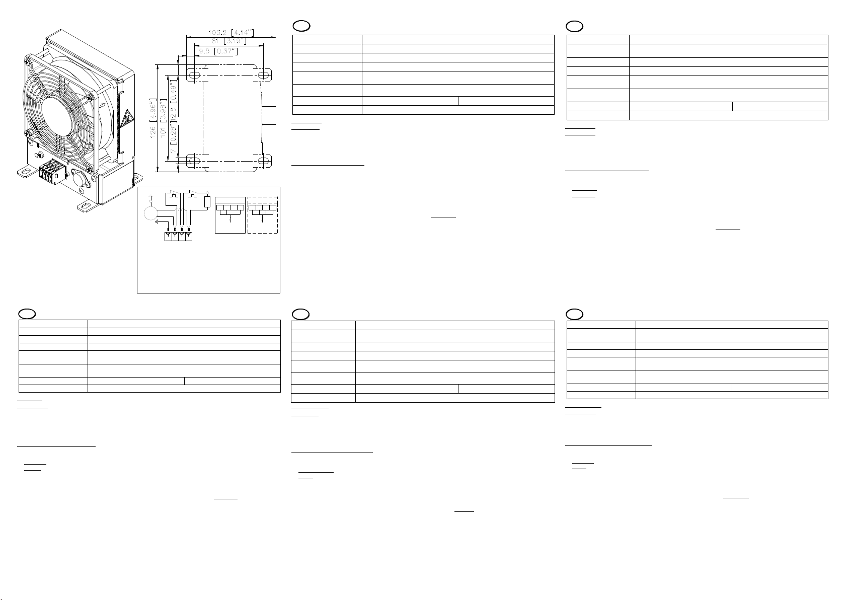
Betriebsthermostat / Thermostat / Thermostat
Klemmkontakt / Connection mains / Contact tension
Sicherheitsthermostat / Security thermostat / thermostat sécurité
Widerstandsheizung / Resistance Heater / Chauffage de résistance
N
L1
LPE
Ventilator / fan / ventilateur
X1
M1
E1
B2
B1
1
L
1~
X1
PE
M1 N
4
B2
2 3
B1 E1
max. 2,5mm² /
AWG
4
L1
OptionStandard
3
L1
L N PE L N
PE
Klemmkontakt Masse / earthing connection / Contact de mise à terre
X40
X40
Phase L und L1 müssen die gleiche Phasenlage haben /
Phase L and L1 must have the same phasing /
L de phase et L1 doivent avoir le même introduire
Refer to specifications on model plate
-20°C..+70°C (heating appliance with fan)
Cable end or plug terminal -connection
Binding post clamping area
Single filament: 2x 0,5 –2,5 mm²
Fine multi-filament: (soldered, wire end sleeve, pin terminal) 2x 0,5 –1,5mm²
Length of stripped insulation
and/or wire end sleeve
Control thermostat +15 .. +25°C
4x M6 Screws (not contained in the scope of delivery)
Device type: Heating appliances with fan.
Application: - Prevents formation of condensation
- Prevents temperature falling too low
Caution: Hot surface after initial operation phase! Risk of injury!
The heating appliances are intended for the use in closed switch cabinets and in rotary area from wind-power plants.
To ensure exact switch cabinet temperature regulation, an external thermostat should be used to regulate theheating
appliance.
Mounting and safety information:
1. The country-specific regulations must be followed when connecting the heating appliance.
Only qualified personnel should connect the heating appliance.
Standard: Regulation over integrated fixed value thermostat B1
Option: Regulation over external contact L1, e.g. Hygrost
The power supply has to be applied to L.
2. For safety reasons, and for optimum air circulation, all neighbouring components and cables must always have a
minimum of 50 mm clearance all-round. Fan-operated heating appliances must always have 100 mm clearance
around the induction and exhaust areas.
3. For improved heat dissipation, install the heating appliance horizontally in the lower part of the switch cabinet (fan
facing down).
4. Caution: Radiation and contact heat: Heating appliancemust not be mounted to easily flammable materials (wood,
plastic etc.).
5. Heating appliances must not be covered during operation.
6. Heating appliances must not be operated in aggressive ambient air.
7. The heating appliances are maintenance-free and for safety reasons must NOT be repaired. When the heating
appliance is no longer needed, it must be disposed of by authorized specialist personnel in accordance with all
applicable environmental protection regulations.
8. Mounting within not stationary area with 4 screws at the mounting flange.
In the stationary area a mounting at a hat rail is optionally possible. Hat rail mounting must take place in such a way
that the spring shows downward.
Handleiding voor verwarmingstoestellen voor schakelkasten FLH ... SL
zie aanduidingen op het typeplaatje
Temperatuurbereik voor
gebruik
AC: -40°C..+70°C; DC: -20°C..+70°C
Aansluiting met draadeinden of steekklemmen
Klembereik van de
aansluitklemmen
eenaderig: 2x 0,5 –2,5 mm²
soepel: (vertind, met ader–eindhuls, met pen–kabelschoen) 2x 0,5 –1,5mm²
Striplengte resp. lengte
van de ader–eindhuls
Regelthermostaat +15 .. +25°C
Veiligheidsthermostaat +90°C
4x M6 schroef (bevat niet in het werkingsgebied van levering)
Toesteltype: Verwarmingstoestellen met ventilator.
Toepassing: - Vermijden van condensatiewatervorming
- Vermijden van te lage temperaturen
Opgelet: warme oppervlakten na ingebruikneming! Blessuregevaar!
De verwarmingstoestellen zijn bedoeld voor toepassing in gesloten schakelkasten, in het roterend gedeelte van
windkrachtinstallaties. Voor een exacte temperatuurregeling van de schakelkast moet een afzonderlijke thermostaat
het verwarmingstoestel sturen.
Montage- en veiligheidsaanwijzingen:
1. Bij het aansluiten van het verwarmingtoestel moeten de plaatselijke voorschriften in acht genomen worden. De
aansluiting mag enkel uitgevoerd worden door gekwalificeerde personen.
Standaard: Regeling via geïntegreerdvaste waarde thermostaat B1
Optioneel: regeling via extern contact L1, bijv. Hygrostaat
ansluiten van de voedingsspanning bij L.
2. Om veiligheidsredenen en voor een optimale luchtcirculatie moet naar naburige bouwelementen en leidingen
rondom een afstand van minimum 50 mm ingehouden worden. Bij verwarmingstoestellen die met ventilator werken,
moet in de aanzuig- en blaaszone een afstand van 100mm ingehouden worden.
3. Voor een beter warmterendement wordt het verwarmingstoestel horizontaal (ventilator omlaag) geïnstalleerd in het
onderste gedeelte van de schakelkast.
4. Opgelet: stralings- en contactwarmte: verwarmingstoestel mag niet gemonteerd worden op licht ontvlambare
materialen (hout, kunststof enz.).
5. Verwarmingstoestellen mogen tijdens het gebruik niet afgedekt worden.
6. Verwarmingstoestellen mogen niet gebruikt worden in een agressieve omgevingslucht.
7. Deverwarmingstoestellen zijn onderhoudsvrij en mogen om veiligheidsredenen niet gerepareerd worden. Als het
verwarmingstoestel niet meer nodig is, moet het door geautoriseerd vakpersoneel overeenkomstig de geldende
voorschriften ter bescherming van het milieu bij het afvalworden verwijderd.
8. Montage in het niet-stationaire gebied met 4 schroeven op de bevestigingsflens. In het stationaire gebied is
bevestiging met de bijgeleverde DIN-rail mogelijk. Bevestiging met DIN-rail moet zodanig geschieden dat de veer
omlaag wijst.
Betriebsanleitung für Schaltschrankheizgeräte FLH ... SL
siehe Angaben auf dem Typschild
AC: -40°C..+70°C; DC: -20°C..+70°C
Klemmbereich der
Anschlussklemme
eindrähtig: 2x 0,5 –2,5 mm²
feindrähtig: (verzinnt, mit Aderendhülse, mit Stiftkabelschuh) 2x 0,5 –1,5mm²
Länge der Abisolierung
bzw. Aderendhülse
Regelthermostat +15 .. +25°C
Sicherheitsthermostat +90°C
4x M6 Schrauben (nicht im Lieferumfang enthalten)
Geräteart: Heizgeräte mit Lüfter.
Anwendung: - Vermeidung von Kondensatwasserbildung
- Vermeidung von Temperaturunterschreitungen
Achtung: Heiße Oberfläche nach Inbetriebnahme! Verletzungsgefahr!
Die Heizgeräte sind für den Einsatz in geschlossenen Schaltschränken und im rotierenden Bereichvon Windkraftanla-
gen vorgesehen. Zur genauen Schaltschrank-Temperaturregelung sollte ein externer Thermostat das Heizgerät
steuern.
Montage- und Sicherheitshinweise:
1. Beim Anschluss des Heizgerätes sind die landesüblichen Vorschriften zu beachten.
Der Anschluss darf nur durch qualifiziertes Fachpersonal erfolgen.
Standard: Regelung über integrierten Festwertthermostat B1
Option: Regelung über externen Kontakt L1, z. B. Hygrostat
Dauerspannungsversorgung an L
2. Aus Sicherheitsgründen und zur optimalen Luftzirkulation ist zu benachbarten Bauteilen und Leitungen allseitig ein
Abstand von mindestens 50mm einzuhalten. Bei lüfterbetriebenen Heizgeräten ist im Ansaug- und Ausblasbereich
ein 100-mm-Abstand einzuhalten.
3. Zur besseren Wärmeausnutzung das Heizgerät im unteren Teil des Schaltschrankes horizontal (Lüfter nach unten)
installieren.
4. Vorsicht: Strahlungs- und Kontaktwärme: Heizgerät darf nicht auf leicht entflammbaren Materialien montiert werden
(Holz, Kunststoff usw.).
5. Heizgeräte dürfen während des Betriebes nicht abgedeckt werden.
6. Heizgeräte dürfen nicht in aggressiver Umgebungsluft betrieben werden.
7. Die Heizgeräte sind wartungsfrei und dürfen aus Sicherheitsgründen nicht repariert werden.
Wird das Heizgerät nicht mehr benötigt, ist es vom autorisierten Fachpersonal gemäß den geltenden Umwelt-
schutzvorschriften zu entsorgen.
8. Montage in nicht stationären Bereich mit 4 Schrauben am Befestigungsflansch. Im stationären Bereich ist eine
Befestigung an einer Hutschiene optional möglich. Hutschienenbefestigung muss so erfolgen, dass die Feder nach
unten zeigt.
Instructions d’emploi des radiateurs en armoires électriques FLH ...SL
Voir les informations figurant sur le boîtier
Plage de température de
fonctionnement
AC: -40°C..+70°C; DC: -20°C..+70°C
Extrémité de câble ou branchement par borne à fiche
Surface de fixation des
bornes de branchement
Monoconducteur : 2x 0,5 –2,5 mm²
À filsde faible diamètre: (étamé avec embout, avec cosse de câble à pointe) 2x 0,5 -1,5mm²
Longueur de dénudage ou
embout
Thermostat de réglage +15 .. +25°C
Thermostat de sécurité +90°C
4x M6 vis (non contenu dans la portée de la livraison)
Type d’appareil : radiateurs soufflants.
Application : - Lutte contre la formation de condensats d’eau
- Lutte contre l’insuffisance de température
Attention: surface brûlante après mise en route ! Danger !
Les radiateurs sont conçus pour une utilisation en armoires électriques fermées et dans la zone de rotation des
installations éoliennes. Le réglage précis de la température du radiateur dans l’armoire électrique doit se faire au
moyen d’un thermostat externe.
Conseils de montage et de sécurité :
1. Pourle branchement du radiateur, la législation en vigueur dansle pays doit êtreobservée.
Le branchement doit être effectuépar du personnel spécialisé etqualifiéuniquement.
Modèlestandard: régulationau moyendu thermostat à valeur fixeB1 intégré
Option:Régulation au moyen d’un contact externeL1,parexempleunhygrostat.
Raccordement de l’alimentation à L.
2. Pour des raisons de sécurité et pour une meilleure circulation de l’air, toutes les pièces et conduites avoisinantes doivent être
tenues à une distance d’au moins 50 mm. Pour les radiateurs soufflants, une distancede 100 mm doit être respectéedans les
zones d’aspiration et de soufflage.
3. Pour une meilleureutilisation dela chaleur, installer le radiateur dans le sens horizontal (aération vers l’arrière) et dans la partie
inférieure de l’armoire électrique.
4. Attention: chaleur de radiation et decontact: le radiateur nedoitpasêtremonté sur desmatériaux facilement inflammables
(bois,plastiqueetc.).
5. Lesradiateurs ne doivent pas être couvertspendantleur utilisation.
6. Lesradiateurs ne doivent pas être utilisésen environnement agressif.
7. Lesradiateurs ne requièrent aucune maintenance et nedoiventpasêtre réparés, pour desraisonsde sécurité. Sile radiateur
est devenu inutile, il doitêtreéliminé par le Personnel spécialisé agréé, conformémentaux consignes de protection de
l’Environnement en vigueur.
8. Lemontage dansune zonenon stationnaire se faitaumoyende4 visà fixersur la bride de fixation.Dansla zone stationnaire,
lafixationpeutêtre réalisée à l’aide du rail fourni. Si vous optez pour la fixation sur rail, le ressort doit être tourné vers le bas.
Bruksanvisning för värmeapparat till kopplingsskåp FLH ... SL
se uppgifter på märkplåten
Användningstemperaturo-
mråde
AC: -40°C..+70°C; DC: -20°C..+70°C
Kabelanslutning eller stickklämanslutning
Anslutningsklämmornas
klämområde
entrådig: 2 x 0,5 –2,5 mm²
fintrådigt: (förtennad med ledarhylsa, med kabelsko) 2 x 0,5 –1,5 mm²
Längd på avisoleringen
resp. ledarändhylsa
Drift termostat +15 .. +25°C
4x M6 Skruv (som inte ingår i leveransen)
Apparattyp: Värmeapparat med fläkt.
Användning: - Undvika kondensvattenbildning
- Undvika att temperaturen underskrids
Varning: Varma ytor efter idrifttagning! Skaderisk!
Värmeaggregaten är avsedda för att användas i slutna kopplingsskåp och i det roterande området i vindkraftverk. För
noggrann temperaturreglering i kopplingsskåpet ska värmeapparaten styrasmed en extern termostat.
Monterings- och säkerhetsanvisningar:
1. Vid anslutning av värmeapparaten ska de i landet gällande bestämmelserna beaktas. Anslutningen får endast
utföras av kvalificerad fackman.
Standard: Reglering genom integrerad termostat för fasta värden B1
Tillval: Reglering genom extern kontakt L1, t.ex. hygrostat
Strömförsörjningen måste anslutas till L.
2. Av säkerhetsskäl och för optimal luftcirkulation ska ett avstånd på minst 50 mm hållas från alla sidor till närliggande
komponenter och ledningar. Vid fläktdrivna värmeapparater ska ett avstånd hållas på 100 mm i området kring insug
och utblås.
3. För bättre värmeutnyttjande av värmeapparaten ska den installeras horisontellt (fläkten nedåt)
i den nedre delen av kopplingsskåpet.
4. Försiktig: Strålnings- och kontaktvärme: Värmeapparat får inte monteras på lättantändliga material (trä, plast o.s.v.)
5. Värmeapparater får inte täckas över under drift.
6. Värmeapparater får inte användas i riskabla omgivningar.
7. Värmeapparater är underhållsfria och får av säkerhetsskäl inte repareras. Om man inte behöver värmeapparaten
längre ska det skrotas av behörigfackpersonal enligt gällande miljöskyddsbestämmelser.
8. Montering i icke stationärt område med 4 skruvar på fästflänsen. I stationärt område finns alternativet att fästa det
på den medföljande hattskenan. Fastsättning med skena måste ske så att fjädern pekar nedåt.
Operating instructions for switch cabinets heating appliances FLH ... SL


