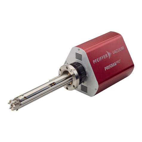
Pfeiffer Vacuum SPM 200 User manual

Operating Instructions
incl. Manufacturer's declaration
BG 805 210 BE / A (0207) 1
Sputter Process Monitor
SPM 200

2BG 805 210 BE / A (0207) SPM 200.om
In all communications with Pfeiffer Vacuum, please specify the information on the
product nameplates. For convenient reference copy the information for all items of
your system into the corresponding nameplate replicas in this document (®26).
This document applies to products with part numbers
PTM26102 / PTM26104 (SPM 200 without pumping station)
PTM26122 (SPM 200 with pumping station)
PTM25265 (QMA 200 Type 2)
B5181408KY (Power supply SP200)
B5181310AQ (Power supply S106-PX)
The part number can be taken from the product nameplate.
This document is based on firmware version
BG509725-H (or higher)
BG509726-H (or higher)
If your unit does not work as described in this document, please check that it is
equipped with the above firmware version.
We reserve the right to make technical changes without prior notice.
The Sputter Process Monitor is a differentially pumped mass spectrometer unit. It is
used for measuring minute trace contamination in sputter processes at process
pressures up to 2×10⁻² mbar.
Training
Pfeiffer Vacuum offers application, operating and maintenance courses for the
best use of this product. Please contact your local Pfeiffer Vacuum
representative.
Prisma™ INFICON AG
Product Identification
Validity
Intended Use
Training
Trademark

BG 805 210 BE / A (0207) SPM 200.om 3
Contents
Product Identification 2
Validity 2
Intended Use 2
Training 2
Trademark 2
1 Safety 4
1.1 Symbols Used 4
1.2 Personnel Qualifications 5
1.3 General Safety Instructions 5
1.4 Liability and Warranty 5
2 Technical Data 6
2.1 System Overview 6
2.2 Standards Implemented 8
2.3 Ambient Conditions 8
2.4 SPM 200 8
2.5 QME 200 9
2.6 Power Supply 9
2.7 Dimensions 10
2.8 Pin Assignment 11
3 Installation 13
3.1 Mechanic Installation 13
3.1.1 Installing the QMA 13
3.1.2 Installing the QME 15
3.2 Electrical Connections 15
3.2.1 Connecting the QME 16
3.2.1.1 Connection 16
3.2.1.2 Control Connection 17
3.2.2 Connecting the Power Supply to the Prisma 19
3.2.3 Connecting the PC 20
3.3 Installing the Software 20
4 Operation 21
4.1 First Time Use 21
4.2 Configuration 22
5 Maintenance 23
5.1 QMA 23
5.1.1 Changing the Filament 23
5.2 QME 25
5.2.1 Cleaning 25
5.2.2 Replacing the Filter Mat 25
5.2.3 "TUNE" of the RF Generator 26
5.2.4 Optimizing the Sensitivity of the Ion Source 27
5.2.5 Replacing the QME 28
6 Accessories and Spare Parts 29
7 Disposal 30
Appendix 31
A: LAN Interface 31
B: Literature 32
Declaration of Contamination 33
Manufacturer's Declaration 34
For cross-references within this document, the symbol (®2XY) is used, for cross-
references to other documents, the symbol (®&[Z]).

4BG 805 210 BE / A (0207) SPM 200.om
1 Safety
DANGER
Information on preventing any kind of physical injury.
WARNING
Information on preventing extensive equipment and environmental damage.
Note
Information on correct handling or use. Disregard can lead to malfunctions or
minor equipment damage.
Note
Caution: dirt sensitive area
Dirt prolongs the pumpdown process.
Always wear clean, lint-free gloves and use clean tools when working
in this area.
... please contact your nearest Pfeiffer Vacuum service center.
The result is O.K.
The result is not as expected.
The lamp/display is lit.
The lamp/display flashes.
The lamp/display is dark.
Labeling
1.1 Symbols Used

BG 805 210 BE / A (0207) SPM 200.om 5
Skilled personnel
All work described in this document may only be carried out by persons who
have suitable technical training and the necessary experience or who have been
instructed by the end-user of the product.
· Adhere to the applicable regulations and take the necessary precautions for the
process media used.
Consider possible reactions between the product materials and the process
media.
Consider possible reactions of the process media due to the heat generated by
the product.
· Adhere to the applicable regulations and take the necessary precautions for all
work you are going to do and consider the safety instructions in this document.
· Before beginning to work, find out whether any vacuum components are con-
taminated. Adhere to the relevant regulations and take the necessary precau-
tions when handling contaminated parts.
Communicate the safety instructions to all other users.
Pfeiffer Vacuum assumes no liability and the warranty becomes null and void if the
end-user or third parties
· disregard the information in this document
· use the product in a non-conforming manner
· make any kind of interventions (modifications, alterations etc.) on the product
· use the product with accessories not listed in the corresponding product
documentation.
The end-user assumes the responsibility in conjunction with the process media
used.
1.2 Personnel Qualifications
1.3 General Safety
Instructions
1.4 Liability and Warranty

6BG 805 210 BE / A (0207) SPM 200.om
2 Technical Data
Note
In all communications with Pfeiffer Vacuum, please specify the
information on the product nameplates. For convenient reference copy
the information for all items of your system into the corresponding
nameplate replicas in this document.
Typ:
No:
F-No:
V A
Pfeiffer Vacuum, D-35614 Asslar
Typ: No: F-No:
Pfeiffer Vacuum
D-35614 Asslar
Only for PTM26102 / PTM26104
2.1 System Overview
Quadrupole electronics
QME 200 with 90° connection
Analyzer QMA 200
SPM Channeltron
Power supply SP 200

BG 805 210 BE / A (0207) SPM 200.om 7
Version: 6.xx SPM 200 - x
Key-Nbr.: xxxx
No: PT 882239 - T
Date: Copyright (C)
QUADSTAR 422 QMS 422
®229
Comprising:
TMU 071 Turbomolecular drag pump, air cooled, with vent valve ®&[8]
MVP 015 Diaphragm pump ®&[9]
PCU 200 Pump control unit ®&[5]
Power supply for PCU 200 ®&[8]
SVV 040 PM Gate valve ®&[11]
RC 200 Remote control unit ®&[6]
Power cable
Software Quadstar
Accessories
Pumping system

8BG 805 210 BE / A (0207) SPM 200.om
Safety
QME/QMA EN 61010-1:1993
IEC1010-1:1990 +A1:1992
protection class I
SP 200 DIN EN 60950
IEC 950, UL 1950
CSA 22.2 No. 234
EMC
immunity EN 50082-2
emission EN 50081-1
Use indoors only
Altitude max. 2000 m NN
Type of protection IP 30
Contamination degree 2
Temperatures
storage/transport -25 … +70 °C
operation QME 0 … +40 °C
SP 0 … +40 °C
Relative humidity max. 80% up to 31 °C,
linearly decreasing to 50% at 40 °C
SPM 200
Mass range u 1 … 100 1 … 200
Detector type Channeltron / Faraday
Detection limit (in argon at
1×10⁻² mbar)
hydrogen
water vapor
nitrogen
oxygen
carbon dioxide
ppm
ppb
ppb
ppb
ppb
< 3
< 500
< 100
< 100
< 100
<20
<500
<200
<200
<200
Contribution to neigh-
boring mass 40/41 ppm < 50
Process pressure max. 1) mbar 1×10⁻²
QMA operating
temperature °C 0 … +100
Bakeout temperature
(QME removed) °C max. +200
SPM ion source 2 yttrium oxide filaments
Mounting orientation any (depending on turbo pump)
Weight kg 8
Connection flange DN 40 CF
1) Versions for process pressures up to 10 mbar on request.
2.2 Standards Implemented
2.3 Ambient Conditions
2.4 SPM 200

BG 805 210 BE / A (0207) SPM 200.om 9
Measurement channels 64
Measurement modes Scan analog, Scan Bargraph, MID
Measurement cycles Mono-/multichannel 1 … 9999 cycles
or repeat
Measurement data buffer 128 Kbyte
MID-dwell 10 ms ... 60 s
Measuring speed
scan analog + bargraph peak
scan bargraph stair
200 ms/u … 60 s/u
20 ms/u … 60 s/u
Electrometer amplifier 10-5 … 10-12 A (f.s.), fix and autorange
Signal filter FIR Filter
Power supply 24 V= / 2.0 A
Interfaces
RS-232-C
LAN
300 … 19200 bit/s
Arcnet, fiber-optic (1000 m max.) 2.5 Mbit/s
Inputs
2 analog differential
1 compact gauges or
external interlock
1 digital in (EXT_RUN)
-5.12 … +5.12 V, 11 bit, 1)
TPR 265, PKR 261
Sink current 0.5 mA (5 V=)
TTL, pull-up 4.7 kohm to +5 V
Outputs
4 analog
2 relay
-5.12 … +5.12 V, 16 Bit, 1 mA max., 200 ohm
closing contact, 24 V~, 30 V=, 1 A
Weight 2.8 kg
SP 200 S 106 -PX
Voltage 90 … 260 V~ 95 … 264 V~
Frequency 47 … 63 Hz 50/60 Hz
Power specifications 1.5 A @ 115 V / 60 W
0.8 A @ 230 V / 60 W
2.7 A max.
Output voltage 24 V=, stabilized 24 V=, stabilized
Isolation 10 Mohm min., output
to ground
> 500 V=
output to ground
Overvoltage category II (according to
EN 61010)
Weight 0.7 kg 2.0 kg
1) By series connection of 2 110 kohm resistors, 1 %, in both lines, the range is
extended to ±10.24 V.
2.5 QME 200
2.6 Power Supply

10 BG 805 210 BE / A (0207) SPM 200.om
321
390 35
2.7 Dimensions
SP 200
SPM 200

BG 805 210 BE / A (0207) SPM 200.om 11
TPR or PKR Digital input Amphenol C91b
6-pin female
Pin Assignment
1 IDENT EXT_PROT
2 SUPP_COM COM
3 SIGNAL -
4 SIG_COM -
5 SCREEN SCREEN
6 SUPPLY -
WARNING
If you are using this connection, install a shielded cable to ensure electro-
magnetic compatibility. The shield should contact the connector case at one end.
The other end should remain open or be grounded to prevent damaging
compensating currents.
control
Pin Assignment D-Sub. H-Density
15-pin, female
1 AO_CH 1 + AO 1
2 AO_CH 2 + AO 2
3 AO_CH 3 + AO 3
4 AO_CH 4 + AO 4
5 AO_COM
6 AI_CH 0 + AI 0
7 AI_CH 0 -
8 AI_CH 1 + AI 1
9 AI_CH 1 -
10 EXT_RUN DI 1
11 REL_1A DO 0
12 REL_1B
13 REL_2A DO 1
14 REL_2B
15 GND
Case Shield
WARNING
If you are using the control and/or RS-232-C connection, install a screened cable
to ensure electromagnetic compatibility. The shield should contact the connector
case at one end. The other end should remain open or be grounded to prevent
damaging compensating currents.
2.8 Pin Assignment
12
63
45
tune
control LAN
ready
24V
RS-232-C
VACUUM
11
15
6
10
1
5
tune
control LAN
ready
24V
RS-232-C
VACUUM

12 BG 805 210 BE / A (0207) SPM 200.om
LAN
Pin Assignment JIS F07
(TOSLINK)
T Transmit
R Receive
RS-232-C
Pin Assignment Pin Assignment D-Sub.
9-pin male
1 n.c 6 n.c
2 Received Data (RXD) 7 optional signal
Request To Send (RTS)
3 Transmitted Data (TXD) 8 optional signal
Clear To Send (CTS)
4 optional signal
Data Terminal Ready
(DTR)
9 n.c
5 Signal Ground (SGND) Case Shield
24 V DC
Pin Assignment 3-pin female
1 + 24 V DC
2 GND
3 GND
Case Screen
QMA
Pin Assignment 13-pin, male
1 Reserve
2 Extr
3 Focus
4 HV
5 Filament 1
6 Filament 2
7 Anode
8RF–
9 GND
10 GND
11 RF +
12 Filament Common
13 EP
61
95
1
23
6
7
8
9
10
11
13
12 1
2
3
4
5
tune
control LAN
ready
24V
RS-232-C
VACUUM
WARNING
This connector carries hazardous voltages!
T
R
tune
control LAN
ready
24V
RS-232-C
VACUUM

BG 805 210 BE / A (0207) SPM 200.om 13
3 Installation
DANGER
Caution: damaged product
Putting a damaged product into operation can be extremely
hazardous.
In case of visible damages, make sure the product is not put into
operation.
Note
Caution: vacuum component
Dirt and damages impair the function of the vacuum component.
When handling vacuum components, take appropriate measures to
ensure cleanliness and prevent damages.
DANGER
No hazardous live voltages must be transferred to the electrode system of the
QMA 200 (due to contact, arcs, plasmas, ion or electron beams, etc.). If there are
such potential hazards in the vacuum chamber protective measures (e.g. better
placement, screening, grounding, etc.) must be implemented there to prevent
such influences. Even lower external voltages acting on the QMA can damage
the electronics or affect the measurement results. Take the same measures as
above to prevent such influences.
DANGER
Establish an electrically conductive connection between the analyzer flange and
the correctly grounded vacuum system using all six screws.
WARNING
Make sure to correctly install the QMA from a vacuum technological point of
view, i.e. the gases to be detected must have unhindered access to the analyzer.
Coating of the analyzer must be prevented.
Skilled personnel
If the flange at the system is not grounded, connect the flange of the QMA 200
(grounding screw M4) to ground using a separate conductor. Make the ground
connection with a yellow/green or an unisolated stranded copper conductor:
·2.5 mm² if mechanically protected (according to DIN VDE 110 T540)
·4.0 mm² if unprotected
3.1 Mechanic Installation
3.1.1 Installing the QMA

14 BG 805 210 BE / A (0207) SPM 200.om
Note
The QMA should be mounted horizontally (with the lining groove
pointing downward). This ensures optimum protection of the QME
against falling objects, ease of installation and excellent access to the
front panel.
On the Prisma with 90° connection this results in a vertically
suspended arrangement of the QME 200.
Carefully remove the
transport safety device
from the QMA and
store it for future use.
Establish a flange
connection between the
analyzer and the
process chamber or
valve.
Flange the turbo-
molecular drag pump to
the analyzer (if not yet
mounted).

BG 805 210 BE / A (0207) SPM 200.om 15
DANGER
The QME may only be connected to a correctly installed QMA because it will be
connected to ground only via the flange of the QMA.
The 24 V feeder line from the SP 200 must not be connected unless the
connection between the QMA and the QME is firmly screw fastened.
With a 4 mm Allen wrench loosen the two screws at the black plastic
connection piece of the QME as much as necessary for the moving part to
have a play of 2 … 3 mm.
Carefully slide the QME onto the mounted QMA up to the notch mark. Make
sure the positioning on the QME through the grounding tab and the lining
groove is correct. Do not apply too much force.
Firmly tighten the two hexagon socket screws. The screws are used for
both, mechanically fastening the QME and making the equipment electri-
cally safe by providing ground contact.
DANGER
Caution: line voltage
Products that are not professionally connected to ground can be
extremely hazardous in the event of a fault.
Connect the product according to the local regulations and ground it
correctly.
WARNING
All electrical connections must have strain relief. Route the cables separately
from EMI sources.
3.1.2 Installing the QME
3.2 Electrical Connections
Lining groove
Grounding tab
Score

16 BG 805 210 BE / A (0207) SPM 200.om
WARNING
Centrally connect all interconnected units (pumping station, SP 200, computers,
recorders, etc.) to ground at the same point to ensure electromagnetic compati-
bility. You can do this by using a multiple AC power outlet or preferably a central
power distributor with power switch.
Exception:
Use a LAN interface for remotely installed computers and/or an environment with
strong electromagnetic fields.
This connection allows vacuum measurement with a TPR or PKR Compact Gauge
to protect the filament FIL and the Channeltron SEM.
TPR
Pirani Compact Gauge
or
PKR
FullRange™Compact Gauge
or
If a TPR or PKR Compact Gauge is connected, the total pressure dependent
control and monitoring of the SEM and filament supplies may be activated. The
switching thresholds can be set via the software (®Quadstar Tune Up / Tune / Ion
Source).
The function can be selected with the SEM+FIL parameter:
®&Quadstar, section "Parameter Setup: QMS Configuration"
EXTERNAL:
The SEM and filament supplies are turned on and off automatically as a function of
the total pressure.
EXT_PROT:
The SEM and filament supplies are turned off when the set total pressure threshold
(Protection) is exceeded. They are turned on by the software when the total
pressure is below the set power-off threshold (Protection).
INTERNAL:
The SEM and filament supplies are turned on and off by the software.
3.2.1 Connecting the QME
3.2.1.1 Connection
Total pressure
measurement
and protection functions
Control via TPR / PKR
tune
control LAN
ready
24V
RS-232-C
VACUUM
Digital
input
• Control input for locking the Channeltron and
the internal filament supply or
• Free digital input
5×10-
4
... 1000 mbar
5×10-
9
... 1000 mbar

BG 805 210 BE / A (0207) SPM 200.om 17
If no pressure gauge is connected, the filament and Channeltron can be controlled
via a floating contact between the signal lines EXT-PROT and COM.
The function is selected with the SEM+FIL parameter :
®&Quadstar, section "Parameter Setup: QMS Configuration"
EXTERNAL:
Direct switching of the SEM and filament supplies:
Contact open Þoff
Contact closed Þon
EXT_PROT:
Only the SEM and filament supplies can be turned off (Protection). They are
switched on by the software if the contact was previously closed.
Open contact ÞSwitch off
If the SEM+FIL control is not used, the input can be used as digital input for a
floating contact between the signal lines EXT_PROT and COM. For this purpose,
set the configuration parameter SEM+FIL to INTERNAL.
Logic assignment: Contact open: ÞDI 0 = true
Contact closed: Þ DI 0 = false
Digital input Digital outputs Analog inputs Analog outputs
• External start of
measurement
cycle or
• Free digital input
(a second digital
input is available
according to
section 3.2.1.1).
Switching thresholds
or
valve open/closed
Reading in of
measured values
e.g. pressure, tem-
perature, gas flow
• Measured values
e.g. ion currents
• Calculated values
e.g. concentration
Specifications and pin assignments ®29, 11
External start of measurement cycles with a floating contact between the signal
lines EXT_RUN and GND. There are four control methods:
Control with contact
Digital input
3.2.1.2 Control Connection
External start of
measurement cycles
tune
control LAN
ready
24V
RS-232-C
VACUUM

18 BG 805 210 BE / A (0207) SPM 200.om
®&Communication protocol QMS 200: [4]
(Frame No. 60; not supported by Quadstar):
INTERNAL:
The measurement cycle is started and stopped by the software
EXT-AUTO:
The start is initiated with the positive edge of the EXT_RUN signal. The
measurement cycle runs until it is aborted with <halt> or until the selected number
of measurement cycles has been performed.
EXT-NORM
The start is initiated with the positive edge of the EXT_RUN signal. The
measurement cycle runs as long as the trigger level is high or until the
measurement cycle is aborted with <halt> or until the selected number of
measurement cycles has been performed.
EXT-SNGL:
The start is initiated with the positive edge of the EXT_RUN signal. However, <run>
must be entered previously. The measurement cycle runs until it is aborted with
<halt> or until the selected number of measurement cycles has been performed.
If the "External measurement cycles/Start" is not used, the EXT_RUN connection
can be used as digital input for polling a contact state. For this use, set the
cycle/TRIG parameter to INTERNAL:
Logic assignment: Contact open: ÞDI 1 = true
Logic assignment: Contact closed: ÞDI 1 = false
Two isolated, normally open relay contacts. They can be assigned to the switching
functions (peak height monitoring) or they can be used as software controlled
outputs, e.g. for switching of valves.
Signal: REL_1A ; REL_1B ÞDO 0
REL_2A ; REL_2B ÞDO 1
Logic assignment: DO .. = true ÞContact closed
Four analog output channels with a common reference point AO_COM.
They may be assigned to measurement channels or controlled by the software, e.g.
for outputting calculated concentrations.
Signal: AO_CH 1 + ; AO_COM ÞAO - Channel 1
AO_CH 2 + ; AO_COM ÞAO - Channel 2
AO_CH 3 + ; AO_COM ÞAO - Channel 3
AO_CH 4 + ; AO_COM ÞAO - Channel 4
Two differential, high impedance analog inputs. They may be assigned to the
measurement channels or read directly by the software.
Signal: AI_CH 0 + ; AI_CH 0 – ÞAI - Channel 0
AI_CH 1 + ; AI_CH 1 – ÞAI - Channel 1
Parameter: cycle /TRIG
Digital input
Digital output
Analog output
Analog input

BG 805 210 BE / A (0207) SPM 200.om 19
WARNING
Do not plug in the SP 200 power connector yet (®221).
Note
The SP 200 power supply is only used in combination with part numbers
PTM26102 and PTM26104. For part number PTM26122, the power supply
B5181310AQ is connected to the Prisma with the cable B5181408K8.
tune
control LAN
ready
24V
RS-232-C
VACUUM
Install the power supply so that:
• it does not get wet, e.g. by water spilled on the floor
• the air circulation is not impeded and the ambient conditions are met.
Insert the outlet connector of the corresponding power supply into the 24 V=
connector of the QME.
3.2.2 Connecting the Power
Supply to the Prisma
SP 200

20 BG 805 210 BE / A (0207) SPM 200.om
Switch on your PC and install the supplied Quadstar software.
The RGA program is also loaded during installation
®&Quadstar [1].
The installation program creates the "SPM 200" group (if it does not exist yet).
3.2.3 Connecting the PC
tune
control LAN
ready
24V
RS-232-C
VACUUM
A
RCNET
Karte im PC
PC
3.3 Installing the Software
Open the supplied Quadstar
software package
Take the enclosed cables.
Establish the connections.
RS-232-C Interface:
Use the supplied 9-pole null
modem cable.
(If required use the extension cable
and/or the DB9 male / DB25 female
adapter).
®&Quadstar [1]
LAN Interface:
If a LAN interace is used:
®231
®&Quadstar [1]
Table of contents
Other Pfeiffer Vacuum Laboratory Equipment manuals
Pfeiffer Vacuum
Pfeiffer Vacuum PRISMAPRO QMG 250 User manual

Pfeiffer Vacuum
Pfeiffer Vacuum Prisma 80 QMS 200 User manual

Pfeiffer Vacuum
Pfeiffer Vacuum HIQUAD QMG 700 User manual

Pfeiffer Vacuum
Pfeiffer Vacuum PRISMAPRO QMG 250 User manual

Pfeiffer Vacuum
Pfeiffer Vacuum PRISMAPRO QMG 250 User manual

Pfeiffer Vacuum
Pfeiffer Vacuum QMG 422 User manual

Pfeiffer Vacuum
Pfeiffer Vacuum Prisma QMS 200 User manual

Pfeiffer Vacuum
Pfeiffer Vacuum HIQUAD QMG 700 User manual

Pfeiffer Vacuum
Pfeiffer Vacuum PRISMAPRO QMG 250 User manual