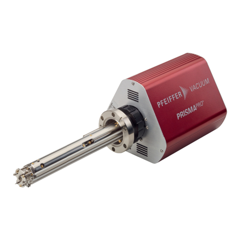
Pfeiffer Vacuum PRISMAPRO QMG 250 User manual

OPERATING INSTRUCTIONS
EN
Translation of the Original
QMG 250 PRISMAPRO®
Compact mass spectrometer

Dear Customer,
Thank you for choosing a Pfeiffer Vacuum product. Your new mass spectrometer should
support you in your individual application with full performance and without malfunctions. The
name Pfeiffer Vacuum stands for high-quality vacuum technology, a comprehensive and
complete range of top-quality products and first-class service. From this extensive, practical
experience we have gained a large volume of information that can contribute to efficient
deployment and to your personal safety.
In the knowledge that our product must avoid consuming work output, we trust that our
product can offer you a solution that supports you in the effective and trouble-free
implementation of your individual application.
Please read these operating instructions before putting your product into operation for the
first time. If you have any questions or suggestions, please feel free to contact info@pfeiffer-
vacuum.de.
Further operating instructions from Pfeiffer Vacuum can be found in the Download Center on
our website.
Disclaimer of liability
These operating instructions describe all models and variants of your product. Note that your
product may not be equipped with all features described in this document. Pfeiffer Vacuum
constantly adapts its products to the latest state of the art without prior notice. Please take
into account that online operating instructions can deviate from the printed operating
instructions supplied with your product.
Furthermore, Pfeiffer Vacuum assumes no responsibility or liability for damage resulting from
the use of the product that contradicts its proper use or is explicitly defined as foreseeable
misuse.
Copyright
This document is the intellectual property of Pfeiffer Vacuum and all contents of this
document are protected by copyright. They may not be copied, altered, reproduced or
published without the prior written permission of Pfeiffer Vacuum.
We reserve the right to make changes to the technical data and information in this document.
2/86

Table of contents
1 About this manual 8
1.1 Validity 8
1.1.1 Applicable documents 8
1.1.2 Variants 8
1.2 Target group 9
1.3 Conventions 9
1.3.1 Instructions in the text 9
1.3.2 Pictographs 10
1.3.3 Stickers on the product 10
1.3.4 Abbreviations 11
1.4 Trademark proof 11
2 Safety 12
2.1 General safety information 12
2.2 Safety instructions 12
2.3 Safety precautions 15
2.4 Proper use 16
2.5 Foreseeable improper use 16
2.6 Responsibilities and warranty 16
2.7 Owner requirements 16
2.8 Personnel qualification 16
2.8.1 Ensuring personnel qualification 17
2.8.2 Personnel qualification for maintenance and repair 17
2.8.3 Advanced training with Pfeiffer Vacuum 17
2.9 Operator requirements 17
3 Product description 18
3.1 Scope of delivery 18
3.2 System overview 18
3.2.1 Structure of the system 18
3.2.2 Analyzer QMA 250 20
3.2.3 Electronic unit QME 250 21
3.2.4 PV MassSpec software 22
3.3 Interfaces 22
3.3.1 POWER SUPPLY 22
3.3.2 Ethernet (LAN) 23
3.3.3 AUX I/O 23
3.3.4 EXT I/O 24
3.3.5 TP GAUGE 26
3.3.6 USB 26
3.4 Identifying the product 26
3.5 Operating principle 27
4 Transport and storage 28
4.1 Transporting the product 28
4.2 Storing the product 28
5 Installation 29
5.1 Installing PrismaPro 29
5.2 Installing the analyzer 30
5.3 Assemble the electronic unit 33
5.4 Establishing an electrical connection 33
5.4.1 Establishing the Ethernet connection 33
5.4.2 Connecting the current supply 34
5.5 Connecting gauges 34
5.6 Establishing a network connection 35
Table of contents
3/86

5.6.1 IP addresses 35
5.6.2 Sub-networks 36
5.6.3 Changing the PrismaPro IP address 36
5.6.4 Changing the host computer IP address 36
5.7 Connecting the PrismaPro 37
5.7.1 Connecting each individual PrismaPro 37
5.7.2 Connecting several PrismaPro devices 37
5.8 Installing PV MassSpec 38
6 Commissioning 39
6.1 Commissioning the device 39
6.2 Switch on the device 39
7 Operation 41
7.1 Using PrismaPro Web UI 41
7.2 Use PV MassSpec 41
8 Decommissioning 42
9 Maintenance 43
9.1 Execution of maintenance work 43
9.2 Test report 43
9.3 Maintaining the analyzer QMA 250 44
9.3.1 Visually inspect the QMA 250 analyzer 45
9.3.2 Baking out the analyzer 47
9.4 Replace filament unit 47
9.4.1 Replacing the filament unit of the open ion source 48
9.4.2 Replacing the filament unit of the crossbeam ion source 50
9.4.3 Replacing the filament unit of the grid ion source 51
9.5 Replacing the ion source 53
9.5.1 Replacing the open ion source 53
9.5.2 Replacing the cross beam ion source 54
9.5.3 Replacing the grid ion source 56
9.6 Calibrating high frequency and the mass scale 57
9.6.1 Factory calibration 57
9.6.2 Attaining a stable operating temperature for PrismaPro 58
9.6.3 Selecting the gas mixture for the mass calibration 58
9.6.4 Setting high frequency for both polarities 58
9.6.5 Perform mass calibration (TUNE) 59
9.6.6 Calibrating with a test gas mixture 60
9.6.7 Calibration with process gases 60
9.6.8 Calibration of the helium leak detection 60
10 Malfunctions 61
10.1 Troubleshooting 61
10.1.1Remedying system and communication errors 61
10.1.2Remedying hardware errors 62
10.1.3Remedying operating and measuring errors 65
10.1.4Calling software error messages from PV MassSpec 66
10.2 Contacts on QMA 250 and QME 250 67
10.3 Checking the QMA 250 analyzer 67
11 Shipping 69
12 Recycling and disposal 70
12.1 General disposal information 70
12.2 Dispose of a compact mass spectrometer 70
13 Service solutions by Pfeiffer Vacuum 71
14 Ordering information 73
Table of contents
4/86

14.1 Ordering parts 73
14.2 Spare parts Maintenance Level 1 73
14.2.1Electronic unit QME 250 73
14.2.2Analyzer QMA 250 73
14.2.3Filament units 74
14.3 Spare parts Maintenance Level 2 74
14.4 Spare parts and small parts sets 74
14.4.1Spare parts 74
14.4.2Set of small parts PT 163 544 for open ion source 75
14.4.3Set of small parts PT 163 543 for crossbeam ion source 75
14.4.4Set of small parts PT 163 534 for grid ion source 75
15 Technical data and dimensions 76
15.1 General 76
15.2 Technical data PrismaPro QMG 250 F 76
15.3 Technical data PrismaPro QMG 250 M 77
15.4 Dimensions 79
NRTL certification 83
Declaration of conformity 84
Table of contents
5/86

List of tables
Tbl. 1: Applicable documents 8
Tbl. 2: QMG 250 PrismaPro 8
Tbl. 3: Analyzer QMA 250 9
Tbl. 4: Electronic unit QME 250 9
Tbl. 5: Abbreviations used 11
Tbl. 6: Ion sources for analyzer QMA 250 M 21
Tbl. 7: Front panel elements 22
Tbl. 8: Status of the Ethernet connection 23
Tbl. 9: Required tightening torques 30
Tbl. 10: Gauges 34
Tbl. 11: Examples for sub-networks 36
Tbl. 12: Connections of the filament and the ion source 46
Tbl. 13: Maximum bakeout temperatures 47
Tbl. 14: Mass calibration 58
Tbl. 15: System and communication errors 62
Tbl. 16: Hardware errors 64
Tbl. 17: Operating and measuring errors 66
Tbl. 18: Software error messages from PV MassSpec 66
Tbl. 19: Measurements for checking the analyzer 68
Tbl. 20: Electronic unit QME 250 73
Tbl. 21: Analyzer QMA 250 74
Tbl. 22: Filament units 74
Tbl. 23: Ion sources 74
Tbl. 24: Spare parts 75
Tbl. 25: Set of small parts PT 163 544 for open ion source 75
Tbl. 26: Set of small parts PT 163 543 for crossbeam ion source 75
Tbl. 27: Set of small parts PT 163 534 for grid ion source 75
Tbl. 28: Conversion table: Pressure units 76
Tbl. 29: Conversion table: Units for gas throughput 76
Tbl. 30: Technical data PrismaPro QMG 250 F 77
Tbl. 31: Technical data PrismaPro QMG 250 M 79
List of tables
6/86

List of figures
Fig. 1: Position of the stickers on the product 10
Fig. 2: Main components of the PrismaPro 19
Fig. 3: System overview 20
Fig. 4: Analyzers with transport protection 20
Fig. 5: Components of the analyzer QMA 250 with open ion source 21
Fig. 6: QME 250 front panel: left standard, right with IO 250 22
Fig. 7: PV MassSpec 22
Fig. 8: View on the mains part plug 23
Fig. 9: Ethernet connection 23
Fig. 10: AUX I/O, 15-pin D-Sub socket 23
Fig. 11: EXT I/O, 62-pin HD D-Sub socket 24
Fig. 12: Connection example: Digital output EXT I/O 25
Fig. 13: Connection example: Digital input AUX I/O and EXT I/O 26
Fig. 14: TP GAUGE, 6-pin Amphenol C 091 A socket 26
Fig. 15: Principle of the quadrupole mass spectrometer system 27
Fig. 16: Fastening and grounding of analyzer 32
Fig. 17: Mounting aid and transport protection 32
Fig. 18: Desktop shortcut 38
Fig. 19: Excerpt of an exemplary a test report 44
Fig. 20: Ion source with open ion source as an example 45
Fig. 21: Connections of the filament and the ion source with clamps 46
Fig. 22: High-frequency connections of the quadrupole mass filter 46
Fig. 23: Disassembling the filament unit of the open ion source 49
Fig. 24: Installing the filament unit of the open ion source 49
Fig. 25: Filament unit of the crossbeam ion source 50
Fig. 26: Support spring on the analyzer with crossbeam ion source 51
Fig. 27: Filament unit of the grid ion source 52
Fig. 28: Replacing the open ion source 54
Fig. 29: Replacing the cross beam ion source 55
Fig. 30: Support spring on the analyzer with crossbeam ion source 55
Fig. 31: Replacing the grid ion source 57
Fig. 32: Warning message with security prompt 59
Fig. 33: New high frequency/reverse polarity 59
Fig. 34: Contacts on QMA 250 and QME 250 67
Fig. 35: Dimensions QMG 250 F / open IS / straight QME 250 79
Fig. 36: Dimensions QMG 250 M / open IS / straight QME 250 80
Fig. 37: Dimensions QMG 250 M / crossbeam IS / straight QME 250 80
Fig. 38: Dimensions QMG 250 M / grid IS / straight QME 250 80
Fig. 39: Dimensions QMG 250 F / open IS / 90° QME 250 81
Fig. 40: Dimensions QMG 250 M / open IS / 90° QME 250 81
Fig. 41: Dimensions QMG 250 M / crossbeam IS / 90° QME 250 82
Fig. 42: Dimensions QMG 250 M / grid IS / 90° QME 250 82
List of figures
7/86
1 About this manual
IMPORTANT
Read carefully before use.
Keep the manual for future consultation.
1.1 Validity
This document describes the function of the products listed in the following and provides the most im-
portant information for safe use. The description is written in accordance with the valid directives. The
information in this document refers to the current development status of the products. The document
retains its validity assuming that the customer does not make any changes to the product.
1.1.1 Applicable documents
Designation Document
"PrismaPro Web UI" Operating instructions
QMG 250
BG 6002
Quick-Start Guide "PrismaPro"
QMG 250
BG 6003
Software documentation
PV MassSpec
(part of the software)
Declaration of conformity (part of these instructions)
Tbl. 1: Applicable documents
You can find these documents in the Pfeiffer Vacuum Download Center.
1.1.2 Variants
This document applies to products with the following part numbers:
Part number Designation
PT M15 ... QMG 250 PrismaPro (Faraday)
PT M16 ... QMG 250 PrismaPro (Faraday/electron multiplier)
Tbl. 2: QMG 250 PrismaPro
Part number Short description Mass range [u] Detector Ion source Filament Wiring
PT M25 411 QMA 250 F1 1 – 100 Faraday open W Nickel
PT M25 412 Ir-Y2O3
PT M25 413 QMA 250 M1 Faraday/EM W
PT M25 414 Ir-Y2O3
PT M25 415 CB W Copper, silver-plated
PT M25 416 Ir-Y2O3
PT M25 419 Grid W
PT M25 421 QMA 250 F2 1 – 200 Faraday open W Nickel
PT M25 422 Ir-Y2O3
PT M25 423 QMA 250 M2 Faraday/EM W
PT M25 424 Ir-Y2O3
PT M25 425 CB W Copper, silver-plated
PT M25 426 Ir-Y2O3
PT M25 429 Grid W
About this manual
8/86

Part number Short description Mass range [u] Detector Ion source Filament Wiring
PT M25 431 QMA 250 F3 1 – 300 Faraday open W Nickel
PT M25 432 Ir-Y2O3
PT M25 433 QMA 250 M3 Faraday/EM W
PT M25 434 Ir-Y2O3
PT M25 435 CB W Copper, silver-plated
PT M25 436 Ir-Y2O3
PT M25 439 Grid W
Tbl. 3: Analyzer QMA 250
Part number Short description Mass range [u] Input/Output Version
PT M28 641 QME 250 M1 1 – 100 Standard
(without IO 250)
straight
PT M28 642 QME 250 M2 1 – 200
PT M28 643 QME 250 M3 1 – 300
PT M28 651 QME 250 M1 1 – 100 expanded
(with IO 250)
PT M28 652 QME 250 M2 1 – 200
PT M28 653 QME 250 M3 1 – 300
PT M28 661 QME 250 M1 1 – 100 Standard
(without IO 250)
90° angled
PT M28 662 QME 250 M2 1 – 200
PT M28 663 QME 250 M3 1 – 300
PT M28 671 QME 250 M1 1 – 100 expanded
(with IO 250)
PT M28 672 QME 250 M2 1 – 200
PT M28 673 QME 250 M3 1 – 300
Tbl. 4: Electronic unit QME 250
You can find the part number on the rating plate of the product.
Pfeiffer Vacuum reserves the right to make technical changes without prior notification.
The figures in this document are not to scale.
Dimensions are in mm unless stated otherwise.
1.2 Target group
These operating instructions are aimed at all persons performing the following activities on the product:
●Transportation
●Setup (Installation)
●Usage and operation
●Decommissioning
●Maintenance and cleaning
●Storage or disposal
The work described in this document is only permitted to be performed by persons with the appropriate
technical qualifications (expert personnel) or who have received the relevant training from Pfeiffer Vac-
uum.
1.3 Conventions
1.3.1 Instructions in the text
Usage instructions in the document follow a general structure that is complete in itself. The required ac-
tion is indicated by an individual step or multi-part action steps.
Individual action step
A horizontal, solid triangle indicates the only step in an action.
►This is an individual action step.
About this manual
9/86

Sequence of multi-part action steps
The numerical list indicates an action with multiple necessary steps.
1. Step 1
2. Step 2
3. ...
1.3.2 Pictographs
The pictographs used in the document indicate useful information.
Note
Tip
Wear laboratory gloves
Perform a visual inspection
1.3.3 Stickers on the product
This section describes all the stickers on the product along with their meaning.
D-35614 Asslar
Mod.
P/N
S/N
Input
QMG 250
PT M16 312 210
4452....
24 V DC 1.25 A 30 W
Made in United States 2020/02
Rating plate (example)
Rating plate for PrismaPro
1 2 3
3
Fig. 1: Position of the stickers on the product
1 Rating plate for entire system QMG 250 3 Rating plate for analyzer QMA 250
2 Rating plate for electronic unit QME 250
About this manual
10/86

1.3.4 Abbreviations
Abbreviation Explanation
AI Analog input
AO Analog output
BHCS Button head cap screw
C/B Cross beam (ion source type)
DEC Digital emission controller
DHCP Communication protocol for assigning the network configuration (Dynamic Host
Communication Protocol)
DI Digital input
DO Digital output
DSP Digital signal processing
EE Electron energy
EM Electron multiplier
ESD Electrostatic discharge
FC Faraday cup
FC-5311 Perfluoro(tetradecahydrophenantrene) isomer mixture for mass scale calibration in
the mass range up to 624 u.
GND Ground
HD High density, with D-Sub connections with low pin spacing
HF High Frequency
HV High voltage
IP Intenet Protocol
IQ Ion source
Ir-Y2O3Yttrium oxide (Y2O3) coated iridium (Ir)
LAN Local area network
M Metric ISO thread
MAC Hardware address of a network adapter providing an unambiguous identifier for the
device in a computer network (media access control)
ME Unit of quantity
MSL Mean sea level
PP Partial pressure
PV Pfeiffer Vacuum
RF Radio frequency
RGA Residual gas analysis
TCP/IP Internet protocol family (transmission control protocol/internet protocol)
TP Total pressure
UHV Ultra high vacuum
UTP Unshielded twisted pair (of wires in cable)
W Tungsten
Web UI User Interface via web connection
Tbl. 5: Abbreviations used
1.4 Trademark proof
●PrismaPro® is a registered trademark of Pfeiffer Vacuum GmbH.
●Windows® is a trademark of the Microsoft Corporation.
About this manual
11/86

2 Safety
2.1 General safety information
The following 4 risk levels and 1 information level are taken into account in this document.
DANGER
Immediately pending danger
Indicates an immediately pending danger that will result in death or serious injury if not observed.
►Instructions to avoid the danger situation
WARNING
Potential pending danger
Indicates a pending danger that could result in death or serious injury if not observed.
►Instructions to avoid the danger situation
CAUTION
Potential pending danger
Indicates a pending danger that could result in minor injuries if not observed.
►Instructions to avoid the danger situation
NOTICE
Danger of damage to property
Is used to highlight actions that are not associated with personal injury.
►Instructions to avoid damage to property
Notes, tips or examples indicate important information about the product or about this docu-
ment.
2.2 Safety instructions
Safety instructions according to product’s life stages
All safety instructions in this document are based on the results of a risk assessment.
Pfeiffer Vacuum has taken into account all the relevant life stages of the product.
Risks during installation
DANGER
Danger to life caused by electric voltage on the QME electronic unit
You may only attach the electronic unit to a correctly installed QMA analyzer (earth connection). The
24 V supply line of the SP current supply may never be connected if the connection of the QMA Ana-
lyzer is not screwed tight to the QME electronic unit. Only qualified service personnel may open the
QME electronic unit.
There are no parts in the QME electronic unit that should be maintained by the user.
►Install the QMA analyzer correctly before installing the QME electronic unit.
►Establish a correct earth connection between the components.
►Only have the QME electronic unit opened by qualified service personnel.
►Never operate the QME electronic unit when opened.
Safety
12/86

DANGER
Danger to life caused by electric voltage on the analyzer
During operation, dangerous voltage is present on the electrode system of the QMA analyzer. In un-
favorable conditions, other parts installed in the vacuum chamber (e.g. gauges) may be exposed to
this, and become dangerous to touch. (Also take into account lines and connected devices) You must
arrange or protect these installed parts so that no contact, galvanic connection, flashover, or charge
carrier flow can occur.
►Make sure that the QMA, vacuum chamber, and entire apparatus always have a proper connec-
tion to protective earth.
►Provide additional protection if the user can touch the analyzer when the vacuum system is open.
►Ensure mechanical protection against contact of the analyzer and the parts installed.
►Ensure compulsory separation of the current supply when opening the system (e.g. using a door
contact).
DANGER
Danger to life due to electric voltage
High voltages are present inside the device. When touching parts that are live, there is a risk of
death. If there is visible damage, there is a risk of death when commissioning the device.
►Work on the open device must only be carried out by trained specialist personnel.
►Before carrying out any installation and maintenance work, switch the device off and disconnect
it from the current supply.
–After switching off, wait about 60 seconds and then disconnect all cables (power cable at the
end).
►Never open the device with the current supply connected.
►Secure the current supply against unauthorized or unintentional reactivation.
►Do not insert any objects into the vent openings.
►Never open an external power supply pack.
►Never operate an open or defective device.
►Secure a defective device against accidental operation.
►Protect the device against moisture.
DANGER
Danger to life from electric shock
Inadequate or incorrect grounding of the unit leads to contact-sensitive voltage on the housing. When
making contact, increased leakage currents will cause a life-threatening electric shock.
►Before the installation, check that the connection leads are voltage-free.
►Conduct the electrical connection in accordance with locally applicable regulations.
►Make sure that the local mains voltage and frequency match rating plate specifications.
►Make sure that the mains cable and extension cable meet the requirements for double isolation
between input voltage and output voltage, in accordance with IEC 61010 and IEC 60950.
►Use only a 3-pin mains cable and extension cable with properly connected protective earthing
(earthed conductor).
►Plug the mains plug into a socket with earthing contact only.
►Always connect the mains cable prior to all other cables, to ensure continuous protective earth-
ing.
Risks during operation
CAUTION
Health risks and environmental damage due to the process gases used
Gases used (process gases) represent a health risk and damage to the environment.
►Check the leak tightness of the connections before introducing the process gas.
►Make sure that the exhaust gas system is suitable for the gases supplied.
►Consider potential interactions between the materials and process gases.
►When handling the gases used, observe the applicable guidelines.
►Observe the protective measures.
Safety
13/86

Risks during maintenance
DANGER
Danger to life due to electric voltage
High voltages are present inside the device. When touching parts that are live, there is a risk of
death. If there is visible damage, there is a risk of death when commissioning the device.
►Work on the open device must only be carried out by trained specialist personnel.
►Before carrying out any installation and maintenance work, switch the device off and disconnect
it from the current supply.
–After switching off, wait about 60 seconds and then disconnect all cables (power cable at the
end).
►Never open the device with the current supply connected.
►Secure the current supply against unauthorized or unintentional reactivation.
►Do not insert any objects into the vent openings.
►Never open an external power supply pack.
►Never operate an open or defective device.
►Secure a defective device against accidental operation.
►Protect the device against moisture.
WARNING
Health hazard through poisoning from toxic contaminated components or devices
Toxic process media result in contamination of devices or parts of them. During maintenance work,
there is a risk to health from contact with these poisonous substances. Illegal disposal of toxic sub-
stances causes environmental damage.
►Take suitable safety precautions and prevent health hazards or environmental pollution by toxic
process media.
►Decontaminate affected parts before carrying out maintenance work.
►Wear protective equipment.
WARNING
Risk of burns during baking out
During or immediately after the baking out, the heating jacket and the metal surfaces near to the
heating jacket are extremely hot. The metal surfaces can reach a temperature of over 100 °C. This
causes burns if you do not wear suitable personal protective equipment.
►When baking out, always wear personal protective equipment (for example protective gloves).
►Never touch surfaces without suitable protective gloves, either during or directly after baking out.
Risks when shipping
WARNING
Risk of poisoning from contaminated products
Where products that contain harmful substances are shipped for maintenance or repair purposes, the
health and safety of service personnel is at risk.
►Comply with the instructions for safe distribution.
Safety
14/86

Risks during disposal
WARNING
Health hazard through poisoning from toxic contaminated components or devices
Toxic process media result in contamination of devices or parts of them. During maintenance work,
there is a risk to health from contact with these poisonous substances. Illegal disposal of toxic sub-
stances causes environmental damage.
►Take suitable safety precautions and prevent health hazards or environmental pollution by toxic
process media.
►Decontaminate affected parts before carrying out maintenance work.
►Wear protective equipment.
2.3 Safety precautions
The product is designed according to the latest technology and recognized safety engineering rules.
Nevertheless, improper use can result in danger to operator all third party life and limb, and product
damage and additional property damage.
Duty to provide information on potential dangers
The product holder or user is obliged to make all operating personnel aware of dangers
posed by this product.
Every person who is involved in the installation, operation or maintenance of the product
must read, understand and adhere to the safety-related parts of this document.
Infringement of conformity due to modifications to the product
The Declaration of Conformity from the manufacturer is no longer valid if the operator
changes the original product or installs additional equipment.
●Following the installation into a system, the operator is required to check and re-evalu-
ate the conformity of the overall system in the context of the relevant European Direc-
tives, before commissioning that system.
Safety aspects
●Proper use will guarantee that personnel are provided protection by the device.
●There are no electrical hazards posed by the device as long as proper use is observed as prescri-
bed.
●It is not known that the device generates harmful radiation.
●The analyzer does not contain any poisonous substances.
●Use of the analyzer in applications with toxic process media will result in residues of the toxic me-
dia settling on the surfaces of the analyzer.
●Suitable safety precautions must be observed by the maintenance personnel when working with
contaminated analyzers.
General safety precautions when handling the product
►Observe all applicable safety and accident prevention regulations.
►Check that all safety measures are observed at regular intervals.
►Pass on safety instructions to all other users.
►Do not expose body parts to the vacuum.
►Always ensure a secure connection to the earthed conductor (PE).
►Never disconnect plug connections during operation.
►Observe the above shutdown procedures.
►Keep lines and cables away from hot surfaces (> 70 °C).
►Do not carry out your own conversions or modifications on the device.
►Observe the unit protection degree prior to installation or operation in other environments.
►Provide suitable touch protection, if the surface temperature exceeds 70 °C.
►Inform yourself about any contamination before starting work.
Safety
15/86

2.4 Proper use
The compact mass spectrometer is used for partial pressure analysis. Typical applications are meas-
urement, monitoring and process control tasks in vacuum systems.
►Install, operate and maintain the product only in accordance with these operating instructions.
►Comply with the application limits.
►Observe the technical data.
2.5 Foreseeable improper use
Improper use of the product invalidates all warranty and liability claims. Any use that is counter to the
purpose of the product, whether intentional or unintentional, is regarded as misuse, in particular:
●Use outside the mechanical and electrical application limits (for this purpose, see: Technical data)
●Use for measurements whose results determine the safety of persons or large values
●Use with corrosive or explosive media
●Use outdoors
●Use after technical changes (inside or outside on the product)
●Use with replacement or accessory parts that are inadequate or are not approved
2.6 Responsibilities and warranty
Pfeiffer Vacuum shall assume no responsibilities and warranty if the operating company or a third party:
●disregards this document
●does not use the product for its intended purpose
●carries out any modifications to the product (conversions, changes, etc.) that are not listed in the
corresponding product documentation
●operates the product with accessories that are not listed in the corresponding product documenta-
tion
The operator is responsible for the process media used.
2.7 Owner requirements
Safety-conscious working
1. Only operate the product in a technically flawless state.
2. Operate the product in line with its intended purpose, safety and hazard-conscious and only in
compliance with these operating instructions.
3. Fulfill the following instructions and monitor the observation of the following instructions:
–Proper use
–Generally applicable safety instructions and accident prevention regulations
–International, national and locally applicable standards and guidelines
–Additional product-related guidelines and regulations
4. Only use original parts or parts approved by Pfeiffer Vacuum.
5. Keep the operating instructions available at the place of installation.
6. Ensure personnel qualification.
2.8 Personnel qualification
The work described in this document may only be carried out by persons who have appropriate profes-
sional qualifications and the necessary experience or who have completed the necessary training as
provided by Pfeiffer Vacuum.
Training people
1. Train the technical personnel on the product.
2. Only let personnel to be trained work with and on the product when under the supervision of
trained personnel.
3. Only allow trained technical personnel to work with the product.
4. Before starting work, make sure that the commissioned personnel have read and understood
these operating instructions and all applicable documents, in particular the safety, maintenance
and repair information.
Safety
16/86

2.8.1 Ensuring personnel qualification
Specialist for mechanical work
Only a trained specialist may carry out mechanical work. Within the meaning of this document, special-
ists are people responsible for construction, mechanical installation, troubleshooting and maintenance
of the product, and who have the following qualifications:
●Qualification in the mechanical field in accordance with nationally applicable regulations
●Knowledge of this documentation
Specialist for electrotechnical work
Only a trained electrician may carry out electrical engineering work. Within the meaning of this docu-
ment, electricians are people responsible for electrical installation, commissioning, troubleshooting, and
maintenance of the product, and who have the following qualifications:
●Qualification in the electrical engineering field in accordance with nationally applicable regulations
●Knowledge of this documentation
In addition, these individuals must be familiar with applicable safety regulations and laws, as well as the
other standards, guidelines, and laws referred to in this documentation. The above individuals must
have an explicitly granted operational authorization to commission, program, configure, mark, and earth
devices, systems, and circuits in accordance with safety technology standards.
Trained individuals
Only adequately trained individuals may carry out all works in other transport, storage, operation and
disposal fields. Such training must ensure that individuals are capable of carrying out the required activi-
ties and work steps safely and properly.
2.8.2 Personnel qualification for maintenance and repair
Advanced training courses
Pfeiffer Vacuum offers advanced training courses to maintenance levels 2 and 3.
Adequately trained individuals are:
●Maintenance level 1
─Customer (trained specialist)
●Maintenance level 2
─Customer with technical education
─Pfeiffer Vacuum service technician
●Maintenance level 3
─Customer with Pfeiffer Vacuum service training
─Pfeiffer Vacuum service technician
2.8.3 Advanced training with Pfeiffer Vacuum
For optimal and trouble-free use of this product, Pfeiffer Vacuum offers a comprehensive range of
courses and technical trainings.
For more information, please contact Pfeiffer Vacuum technical training.
2.9 Operator requirements
Observing relevant documents and data
1. Read, observe and follow this operating instruction and the work instructions prepared by the op-
erating company, in particular the safety and warning instructions.
2. Install, operate and maintain the product only in accordance with these operating instructions.
3. Carry out all work only on the basis of the complete operating instructions and applicable docu-
ments.
4. Comply with the application limits.
5. Observe the technical data.
6. Please contact the Pfeiffer Vacuum Service Center if your questions on operation or maintenance
of the product are not answered by these operating instructions.
–You can find information in the Pfeiffer Vacuum service area.
Safety
17/86

3 Product description
3.1 Scope of delivery
The scope of delivery includes the following parts:
●QMG 250 PrismaPro
─Analyzer QMA 250 with transport protection and intermediate piece (EM variant only)
─Electronic unit QME 250
─SP 250 Power supply unit
─Copper gasket DN 40 CF
●Installation hardware and small parts
─Analyzer assembly set (fastening nut, o-ring, 6× hexagon head set screw with nuts (M6) and
washers)
─Socket key for the filament replacement
─assembly tool for QMA 250 Analyzer
●Connector assemblies and cables
─Ethernet cable (UTP patch cable, red, length 3 m, crossed connection)
─D-sub plug (15-pin, male, with housing and strain relief)
─HD D-sub plug 1) (62-pin, male, with housing and strain relief)
─Cable plug 2) (Amphenol, 6-pin, male, for measuring tube connection)
●Documentation
─Operating instructions (multilingual)
─Quick-Start Guide (multilingual)
●Miscellaneous
─Test report (accessible on device)
─Web UI (accessible on device)
─PV MassSpec software (downloadable via PV Cloud)
Unpacking the product and checking completeness of the shipment
1. Unpack the product.
2. Remove the transport fasteners, transport protection etc.
3. Store the transport fasteners, transport protection etc. in a safe place.
4. Check that the shipment is complete.
5. Ensure that no parts are damaged.
3.2 System overview
3.2.1 Structure of the system
The PrismaPro is comprised of 4 main components:
●Analyzer
●Electronic unit
●SP 250 power supply pack with mains cable
●PV MassSpec software
1) Only in conjunction with IO 250 I/O module option
2) Only in conjunction with IO 250 I/O module option
Product description
18/86

1
89
2
7
6
4
3
5
Fig. 2: Main components of the PrismaPro
1 QMA 250 F Analyzer (with Faraday Cup) 6 PV MassSpec software
2 Fastening nut 7 SP 250 power supply pack with mains cable
3 Electronic unit QME 250 (straight design) 8 QMA 250 M Analyzer (with EM)
4 Connection housing 9 Intermediate piece (only with EM version)
5 Electronic unit QME 250 (angled design)
The use of the optional IO 250 I/O module permits the use of additional interfaces. The QME 250 elec-
tronic unit is available with the IO 250 already installed. Pfeiffer Vacuum can, however, also retrofit the
QME 250 electronic unit with a IO 250.
PrismaPro Web UI
You can find detailed information on the use of PrismaPro Web UI in the corresponding op-
erating instructions.
Operation of the PrismaPro is possible via the Web UI user interface, or with the highly comprehensive
PV MassSpec software. Storage of measured data and the evaluation of measurement results is only
possible with the PV MassSpec software. For the operation of PV MassSpec, you will require a PC with
Windows operating system (Windows 7 or higher).
Product description
19/86

AO
DOAI
DI
IO 250
QME 250
SP 250
QMA 250
123
4
5
6
7
8
Fig. 3: System overview
1 Ion source 5 Connection to PC (Ethernet) with PV MassSpec
2 Mass filter 6 Gauges
3 Faraday detector 7 Additional inputs and outputs (analog / digital)
4 Secondary electron multiplier (EM) 8 Voltage supply
3.2.2 Analyzer QMA 250
The analyzer is made up of the following components:
●Ion source
●Quadrupole mass filter
●Ion detector
There are 2 variants of ion detectors:
●Analyzer QMA 250 F with Faraday cup
●Analyzer QMA 250 M with combination of Faraday cup and secondary electron multiplier (EM)
and intermediate piece DN 40 CF-F (116 mm in length)
1
2
34
5
Fig. 4: Analyzers with transport protection
1 Analyzer QMA 250 F 4 Intermediate piece
2 Transport protection 5 Transport protection
3 Analyzer QMA 250 M
The secondary electron multiplier (EM) is a current amplifier working under high-vacuum conditions. An-
alyzers with EM are used for residual gas and trace gas analysis at very low total pressure and applica-
tions in which a high measuring speed is required.
Analyzers with Faraday detector provide a residual gas analysis in the total pressure range > 10-7 hPa.
Pfeiffer Vacuum supplies the analyzer QMA 250 F with Faraday cup in the open ion source version on-
ly. The QMA 250 M is optionally available with open ion source, cross beam ion source, or grid ion
source.
Product description
20/86
Other manuals for PRISMAPRO QMG 250
3
This manual suits for next models
20
Table of contents
Other Pfeiffer Vacuum Laboratory Equipment manuals

Pfeiffer Vacuum
Pfeiffer Vacuum Prisma 80 QMS 200 User manual

Pfeiffer Vacuum
Pfeiffer Vacuum PRISMAPRO QMG 250 User manual

Pfeiffer Vacuum
Pfeiffer Vacuum PRISMAPRO QMG 250 User manual

Pfeiffer Vacuum
Pfeiffer Vacuum Prisma QMS 200 User manual

Pfeiffer Vacuum
Pfeiffer Vacuum PRISMAPRO QMG 250 User manual

Pfeiffer Vacuum
Pfeiffer Vacuum HIQUAD QMG 700 User manual

Pfeiffer Vacuum
Pfeiffer Vacuum SPM 200 User manual

Pfeiffer Vacuum
Pfeiffer Vacuum QMG 422 User manual

Pfeiffer Vacuum
Pfeiffer Vacuum HIQUAD QMG 700 User manual