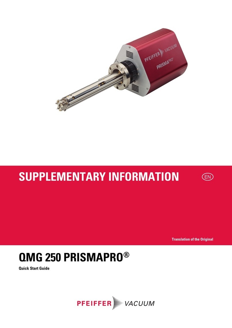
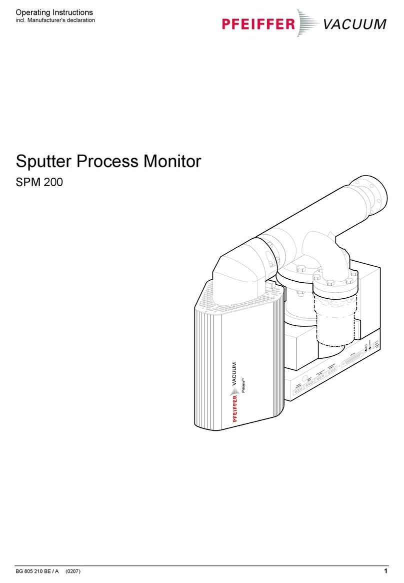
Pfeiffer Vacuum QMG 422 User manual

Operating Instructions
Incl. Declaration of Conformity
BG 805 981 BE (0201) 1
Quadrupole Mass Spectrometer System
QMG 422

2BG 805 981 BE (0201) QMG422.oi
This document applies to QMG 422 systems with QMS 422 and QMI 422 control
units equipped with the modules listed on → 65, some of which come with their
own operating instructions.
It is valid for firmware numbers:
DSP / PRG No. BG 509 732 -..
QMS / PRG No. BG 509 733 -..
CS 422 / PRG No. BG 509 734 -..
The above numbers can be read out with config-TEST or the Quadstar 422
software. The letter (A...Z) at the end of the number represents the modification
index which indicates the firmware level. This operating manual remains valid as
long as only the index changes. In most cases the function is enhanced but also
additional functions may be included that are not described in this edition.
We reserve the right to make engineering changes without notice.
Validity

BG 805 981 BE (0201) QMG422.oi 3
Contents
Validity 2
1 Safety 5
1.1 Symbols used 5
1.2 Intended use 6
1.3 Safety information 6
1.4 Liability and warranty 6
1.5 Courses 6
2 Overview 7
2.1 QMS 422 control unit 8
2.2 QMI 422 control unit 8
2.3 EP 422 Electrometer preamplifier 8
2.4 Family 400 components 9
2.5 Family 125 components 9
2.6 Options 10
3 Technical data 11
3.1 General 11
3.2 QMS 422 control unit 11
3.3 CS 422 operator console 11
3.4 QMI 422 control unit 11
3.5 QC 422 quadruple controller 12
3.6 IS 420 Ion source supply 16
3.7 EP 422 Electrometer 17
3.8 CP 400 Ion counter preamplifier 17
3.9 HV 420 High voltage supply 18
3.10 HV 421 High voltage supply 18
3.11 DI 420 Digital Input 19
3.12 DO 420A Digital Output 19
3.13 AI 421 Analog Input 20
3.14 OH 421 Optical Hub 20
4 Installation 21
4.1 QMS/QMI 422 21
4.2 Overall system 21
4.3 EP 422 22
4.4 CP 400 22
4.5 Cabling with QMA 400 23
4.6 Cabling with QMA 125 24
4.7 RS-232-C interface 25
4.8 LAN interface 26
4.9 Installing/removing options 28
5 Description 31
5.1 Operator console 31
5.2 Functions 33
5.3 Parameter list 35
6 Operation 46
6.1 Initial start up 46
6.2 Filament protection 47
6.3 Degas 47
6.4 Offset correction 47
6.5 Ion counter 48
6.6 Extern input 48
6.7 Simulation 48
6.8 Measurement cycle 49
6.9 Electrometer modes 50
6.10 Mass scan modes 50
6.11 Integral spectrum 52
6.12 Adjust 52
6.13 Analog outputs 55
6.14 Switching functions 58

4BG 805 981 BE (0201) QMG422.oi
7 Troubleshooting 60
7.1 General 60
7.2 Warnings 60
7.3 Error messages 60
7.4 Measurement signal problems 62
7.5 General problems 63
7.6 Service interventions 64
8 Maintenance 64
9 Decommissioning 64
10 Spare parts and accessories 65
Appendix 66
A: Default parameter values 66
B: Literature 68
C: Index 69
Declaration of Contamination 70
Declaration of Conformity 71

BG 805 981 BE (0201) QMG422.oi 5
1 Safety
DANGER
Information on preventing any kind of physical injury.
WARNING
Information on preventing extensive equipment and environmental damage.
Caution
Information on correct handling or use. Disregard can lead to malfunctions or
minor equipment damage.
Skilled personnel
Instructions marked with this symbol may only be carried out by persons who
have suitable technical training and the necessary experience to do it safely.
italic-ITALIC:ITALIC Function-PARAMETERNAME:PARAMETERVALUE
Example: mass-FIRST:12 (starting mass 12 of the mass scan)
1.1 Symbols used

6BG 805 981 BE (0201) QMG422.oi
The QMG 422 is a mass spectrometer designed for gas analysis in the high
vacuum range. It may be used only for this purpose. The instructions in this user’s
guide and in those of the accessories must be conscientiously followed.
DANGER
The QMG 422 is not intended to produce measurement results on which the
safety of persons or large assets depend. For such applications the safety must
be ensured by additional measures.
Adhere to the applicable regulations and take the necessary precautions for the
process media used.
When returning products that have been exposed to the vacuum for maintenance
or repair, enclose a declaration of contamination.
Adhere to the forwarding regulations and prescriptions of the countries and
forwarding agencies concerned.
Before handling any used instruments or components, find out whether they are
contaminated. Adhere to the relevant regulations and take the necessary
precautions when handling contaminated parts.
Pass on the safety information to other users.
Pfeiffer Vacuum assumes no liability and the warranty becomes null and void if the
custodian or third parties
• disregard the information in this document
• use the product in a non-conforming manner
• make any kind of changes (modifications, alterations etc.) to the product
• use the product with accessories not listed in the corresponding product
documentation
The custodian assumes the responsibility in conjunction with the process media
used.
Courses
Pfeiffer Vacuum offers application, operating and maintenance courses for the
best use of this product. Please inquire with your local Pfeiffer Vacuum partner.
1.2 Intended use
1.3 Safety information
1.4 Liability and warranty
1.5 Courses

BG 805 981 BE (0201) QMG422.oi 7
2 Overview
The QMG 422 comprises two equipment families:
In the family 400 the analyzers QMA 400 and QMA 430 (8 mm rod diameter) and
QMA 410 (16 mm rod diameter) and the HF generators QMH 400/410 with mass
ranges of 128 to 2048 amu are used.
400 This symbol refers to information that is applicable only to Series 400
components.
IS 420 QC 422 HV
420/421
QMH
400/410
Ionenquelle Massenfilter Ionennachweis
SEV
Faraday
QMS 422 mit Systembus
Optionen
EP 422/1
EP 422/2
channels
select detect mass amplif
tr i poutputaux di/do config error emiss V1...V6 V7...
sem hv ion sc r cycle
run/h a ltfilamsem
general ion source operation
mono
multi
halt
VACUUM
For an explanation of the abbreviations see Sections 2.3 to 2.7
For ion counting the CP 400 ion counter preamplifier rather than the EP422/2
electrometer is used.
With a QMI 422 rather than QMS 422 no system bus, IS 420 ion source supply, HV
420/421 high voltage supply and options are available.
Family 400

8BG 805 981 BE (0201) QMG422.oi
The family 125 uses the QME 125 mass filter electronics with the mass ranges 100
and 200 amu and QMA 125 analyzers with 6 mm rod diameter.
125 This symbol refers to information that is applicable only to Series 125
equipment.
QC 422
QME 125
EP422
Ionenquelle Massenfilter Ionennachweis
SEV
Faraday
QMI 422
With QMS 422 rather than QMI 422 the system bus and consequently the options
are also available for this family.
The basic unit comprises the power supply,
QC 422 quadrupole controller and the system
bus.
For family 400 components the IS 420 and
HV 420 or HV 421 are installed.
Input/output modules can be installed in
either family.
The QMI 422 comprises the power supply
and QC 422 quadrupole controller and allows
computer operation of family 125 equipment.
QMH/QMA 400 can be operated, but without
ion source and SEM supply.
The only option available is the AO 421
analog output or IC 421 ion counter.
The EP 422 amplifies the very small ion current signals of
the analyzer to voltage levels that are suitable for further
processing. It is installed directly on the analyzers in order
to minimize parasitic noise.
• Compact, simple installation on QMA
• Low-noise, low-drift, little vibration sensitivity
• Fast response and quick recovery form overdriving
400 On analyzers with 90°off-axis SEM, two EP 422 can be connected. This
allows simple changeover from Faraday to SEM mode.
Family 125
2.1 QMS 422 control unit
2.2 QMI 422 control unit
2.3 EP 422 Electrometer
preamplifier

BG 805 981 BE (0201) QMG422.oi 9
The HF generator produces the high-frequency voltage
required for mass separation (→[1]).
QMH type Range QMA type Rod ø
QMH 400-1 128 amu QMA 410 16 mm
QMH 400-5 300 amu QMA 430 8 mm
QMH 400-5 512 amu QMA 400 8 mm
QMH 410-1 1024 amu QMA 400 8 mm
QMH 410-2 2048 amu QMA 400 8 mm
QMH 410-3 340 amu QMA 410 16 mm
QMH 402 16 amu QMA 410 16 mm
Note: In the following QMH 400 or QMA 400 always refers to all types if nothing
else is specified.
The 400 analyzer comprises the ion source, mass filter,
ion collector and housing (→[2]).
Ion collector types:
SEM 217: 90° off-axis with integrated Faraday
SEM 218: 90° off-axis with integrated Faraday and
separate conversion dynode CD
On request: Faraday collector only
The ion source supply is installed in the QMS 422. and
supplies the ion source with the necessary operating
voltages.
• Programmable potentials, short-circuit-proof.
• Polarity reversible for positive and negative ions
• Normal mode/degas mode
• Suitable for all ion source type of the QMA 400
The high-voltage supply is installed in the QMS 422 and
supplies the SEM with the necessary high voltage.
HV 420: For positive ions with SEM 217
HV 421: For positive and negative ions with SEM 217
or for positive ions with the separate
conversion dynode of the SEM 218.
The mass filter electronics QME 125 →[3] comprises
the ion source supply, high frequency generator and
SEM high voltage supply.
QME 125-1: Mass range 100
QME 125-2: Mass range 200
A special version with 6 m cable between QME 125-1
and QMA 125 is available.
The QMA 125 analyzer →[4] comprises the ion
source, mass filter, ion collector and housing.
3 Ion collector types are available:
Faraday, Faraday/Channeltron, 90° SEM
2.4 Family 400 components
QMH 400/410
QMA 400/410/430
IS 420
HV 420 / HV 421
2.5 Family 125 components
QME 125
QMA 125

10 BG 805 981 BE (0201) QMG422.oi
The operator console of the CS 422 is installed in the
QMS 422 and allows manual operation.
The analog output AO 421 and the ion counter IC 421
are mounted on one board which is directly installed in
the QC 422 (without system bus).
The ion counter preamplifier comprises the pulse
coupling, amplifier and pulse height discriminator with
adjustable threshold.
It is installed directly on the QMA with 90°off-axis SEM
and is connected to the IC 421.
.
AI 421: 16 channel analog input module
DI 420: 32 bit digital input module
DO 420A: 32 bit digital output module
PI 420: Dual Pirani module for coarse and fine
vacuum (→[8]).
PE 420: Penning module for high vacuum (→[9]).
OPA 200 network controller board for the ARCNET®
local area network (LAN). It is installed in the PC
(→[6]).
5-Port optical hub (star distributor) for the ARCNET®
local area network (LAN)
Up to 255 nodes can be cascaded
5 or 10 port optical hub (star distributor) for the
ARCNET® local area network (LAN) (→[7]).
2.6 Options
CS 422
AO 421 / IC 421
CP 400
Input/Output
Vacuum measurement
OPA 200
OH 421
OHA 200

BG 805 981 BE (0201) QMG422.oi 11
3 Technical data
This information applies to all components unless specified otherwise.
Ambient conditions
Temperature Storage: –40 °C ... +65 °C / Operation: +5 °C ... +40 °C
Relative humidity ≤80% up to +31 °C, decreasing linearly to 50% at +40 °C
Use indoors, altitude up to 2000 m
Type of protection IP 30: protection >2.5 mm against particles
no protection against water
Standards
Safety EN 61010-1: Protection class 1, pollution degree 2,
overvoltage category II
EMC EN 50081-2, EN 50082-2
Power: 90 ... 265 VAC, 47 ... 63 Hz, 300 Wmax
Dimensions:
177
Weight: 9.6 kg with QC 422 (without additional modules)
Number of slots: Total 17, used by QC 422: 3
Matching to QMS 422
Backlit LCD display, 4 lines of 40 characters each, 5 status LEDs, membrane
keyboard
Weight: 0.75 kg
Power: 90 ... 265 VAC, 47 ... 63 Hz, 200 Wmax
Dimensions:
88
Weight: 6.5 kg with QC 422
3.1 General
3.2 QMS 422 control unit
3.3 CS 422 operator console
3.4 QMI 422 control unit

12 BG 805 981 BE (0201) QMG422.oi
Slots 3 (with and without AO 421 or IC 421)
Number per unit 1
Weight 0.67 kg without / 0.9 kg with AO/IC421
Number of measurement
channels
64
Operating modes MONO / MULTI channel
Measurement cycles 1 ... 10'000, or REPEAT
Channel switching time 1.5 ... 3 ms (with min. PAUSE)
mass-MODE Purpose
SCAN-N
SCAN-F
STAIR
SAMPLE
PEAK-L
PEAK-F
Analog scan normal
Analog scan with FIR filter for measured value
Scan Bargraph
Single mass and MID (Multiple Ion Detection)
Peak search with level criterion
Peak search with FIR FILTER
STEPS per mass 1)
SPEED FIX-Range AUTO-Range
0.5... 1 ms/u 16/u ---
2 ...5 ms/u 32/u ---
10...20 ms/u 64/u2) 16/u
50...100 ms/u 64/u2) 32/u
0.2...60s/u 64/u2) 64/u2)
1) See STEPS →43 2) 32 at mass range 2048
EP 422 or ext. input Ion counter
mass-MODE FIX-Range AUTO-Range AUTO-Range
SAMPLE 0.5 ms ... 60 s 0.5 ms ... 60 s 1 ms ... 60 s
STAIR 0.5 ms/u ... 60 s/u 2 ms/u ... 60 s/u 2 ms/u ... 60 s/u
SCAN 0.5 ms/u ... 60 s/u 10 ms/u ... 60 s/u 20 ms/u ... 60 s/u
PEAK 0.5 ms/u ... 60 s/u 10 ms/u ... 60 s/u 20 ms/u ... 60 s/u
detect-TYPE
FARAD Faraday collector, EP 422
SEM SEM (type configurable), EP 422
ION-CNT Ion counter, CP 400 / IC 421
EXTERN External analog input of the QC 422
PIRANI Pirani
PENNING Cold cathode
A-INPUT Analog signal via AI 421 module
3.5 QC 422 quadruple
controller
Mass scan modes
Mass scale resolution
Measurement speeds
Detectors

BG 805 981 BE (0201) QMG422.oi 13
Detector type Meas. ranges Modes Resolution
FARAD,SEM 10-12 ...10-5 A fsd FIX- and AUTO-
Range
16 bit * (per range)
EXTERN GAIN 1: ±10.240V
GAIN 10: ±1.024V
FIX-Range 16 bit *
ION-CNT 10-2...108 cps,
meaning full use
up to 106...107
cps
AUTO-Range in mass-MODE:
SAMPLE:1/DWELL
STAIR: 2u/SPEED
SCAN:STEPS/SPEED
*) Further increased by averaging
Type Two-stage lowpass, effective for electrometer and external input
Filter time
constant
automatic or selectable in eight steps:
18 , 85 , 400 µs / 1.7, 8, 40, 180, 800 ms
Filter step
response τ63
ts
τ63: Filter time constant
Settling time to ±1‰:
ts≈4 × τ63
NORMAL (N) Low pass (average value)
FIR (F) Finite Impulse Response
AVERAGE Average formed across several measurement cycles
400 Also refer to → 16
Types Axial, cross beam, grid, sputter process monitor, Spec+, Spec-
Parameter sets 4 per ion source
Potentials V1 ... V9
125 Also refer to → [3]
Types Axial, cross beam, grid, sputter process monitor
Emission Standard: 0.07 ... 2 mA; Degas: 0.7 ... 20 mA / 500 V
trip-TYPE: ABS 2 absolute switching functions per channel
trip-TYPE: HYST 1 hysteresis switching function per channel
Reaction time with DO 420A <1 ms after measurement is completed
Measurement ranges and
resolution
Analog filter
Digital filter
Ion sources
Switching functions

14 BG 805 981 BE (0201) QMG422.oi
Detailed description Also refer to → [5]
Measured data buffer 256 kB
Protocol ASCII or binary protocol (according to SECS-1
standard)
1 start, 8 data, 1 stop bit, no parity
Connector 9 pin D-sub, see (→ 25).
Baud rate 300 *), 1200, 2400, 4800, 9600, 19200 baud
Cable length ≤15 m, shielded for baud rate 19200 baud
>15 m, shielded at reduced baud rate
*) Only in conjunction with ASCII protocol
Type ARCNET®with fiber optics
Connection JIS F07 / TOSLINK
Type of fiber PCF 200/230 or 200/300 or APF 980/1000 µm
Distance → 26
Baud rate 2.5 Mbit/s
Wavelength 800 nm
Length of fiber-optic
conductor
0 ... 1000 m
Transmission distance 3000 mmax (cascaded)
RS-232-C interface
LAN interface

BG 805 981 BE (0201) QMG422.oi 15
Connections on QC 422
For EMC reasons only shielded cables may be used on D-Sub connectors. The shield must be connected to
chassis ground. The opposite end may not have a different ground potential.
key
(not used)
A
nalog output of the electrometer signal
0 ... ±10,24 V, Rout : 2× 200 Ω, short-circuit proof
A
nalog input in place of electrometer signal.
±10,24 V, common mode signal: ±2 Vmax, Rin = 2× 50 kΩ
see detect-TYPE:EXTERN 45
Input for ext. measurement cycle start
TTL, int. pull-up 4.7 kΩto +5 V.
see cycle-TRIG 44
Input for filament and SEM protection
TTL, int. pull-up 4.7 kΩto +5 V.
see config-CTRL/SEM+FIL 43
sync
Trigger signal for recording instrument
TTL, Rout >1 kΩ
elm
see above
connector ctrl: ELM OUT
mon (Monitor)
Analog output of the measured value
after digital processing.
0 ... ±10.24 V
Rout : 2× 200 Ω, short-circuit proof
scan
Analog mass number signal
0 ... +10.24 V
Rout : 2× 200 Ωshort-circuit proof
Laboratory sockets, ø2 mm
Connector ctrl
ctrl
95
61
View towards QC
D-Sub, 9-pin female
Pin
5 ELM OUT+
9 ELM OUT–
4 EXT IN–
8 EXT IN+
3 RUN IN
7--
2 EXT PROT
6 GND D
1 GND D
CP (Option)
Connection for CP 400
D-Sub
25 pin male
14 1
13
25
View towards QC
Pin
1 CH 1+
2 CH 2+
3 CH 3+
4 CH 4+
5 CH 5+
6 CH 6+
7 CH 7+
8 CH 8+
9 CH 9+
10 CH 10+
11 CH 11+
12 CH 12+
13 open
Pin
14 CH 1–
15 CH 2–
16 CH 3–
17 CH 4–
18 CH 5–
19 CH 6–
20 CH 7–
21 CH 8–
22 CH 9–
23 CH 10–
24 CH 11–
25 CH 12–
RS 232
Serial interface → 25
LAN
Fiberoptic network interface for high
transmission rates and long distances
TOSLINK TODX 296, duplex
Typ JIS F07
T
R
View towards QC
T Transmit
R Receive
AO (Option)
12 Analog outputs
0 ... ±10.24 V, 1 mAmax
12-Bit, monotonic
Gain: ± 1.7%, Offset: ±21 mVmax
Rout : 2× 200 Ω, short-circuit proof
Rise time: 10 µs to 99%
QMH/QME
Connector for QMH 400/410
or QME 125

16 BG 805 981 BE (0201) QMG422.oi
Slots 5
No. of IS 420 per unit max. 1
Supply 5 V / 0.6 A; ±24 V / 2 A (2.4 A with Degas)
Fuses F1, F2 → 65
Filament supply 0...10 V / 5 Amax / 50 Wmax with Fil1+2: 1.4...2 V on Fil2
Filament modes 1 / 2 / 1+2 (1 in operation, 2 preheated)
Protection 0 ... 5 A Resolution 10 mA
Emission normal 0 ... 2 mA Resolution 10 µA
Emission Degas 0 ... 20 mA Resolution 0.1 mA
Signal SPEC SRC ON 23 V / 70 mA Ri= 110 Ω
Ion source cable Connector PEEK +260 °C Cable SIR -25...+180 °C
Weight 1.45 kg
With ion src-TYPE:SPEC± and EMISS:OFF SPEC SRC ON becomes active. A
relay for changing over the ion source lines can be actuated.
Connector towards
IS 420
111
2
3
4
567
8
9
10
12
13
14 15
16
1
2
3
4
5
6
7
8
QMA GND
SPEC SRC RET
V6, Deflection inner
V3, Focus
V9, Wehnelt
V5, Extraction
Filament +
Filament – / Cathode
9
10
11
12
13
14
15
16
Filament common
V4, Field axis
V0, Ref.Gnd
Screen
V8, Reserve
V1, Ionref
SPEC SRC ON
V7, Deflection outer
Electrode
name
Ref.
direction
Range
[V]
Increm.
[V]
Current
[mAmax]
Degas potential
to V0 [V]
V1 IONREF V1-V0 0 ... 150 1 ±2 +550
V2 CATH V1-V2 0 ... 125 0.5 +2 +7
V3 FOCUS V1-V3 -30 ... +30 0.25 ±2 +550
V4 F-AXIS V1-V4 0 ... 60 0.25 ±0.5 0
V5 EXTRACT V1-V5 0 ... 450 2 ±0.1 0
V6 DEF-I V1-V6 0 ... 450 2 ±0.1 0
V7 DEF-O V1-V7 0 ... 250 1 ±0.1 0
V8 --- V1-V8 -125 ... +125 1 ±0.1 0
V9 WEHNELT V2-V9 0 ... 60 0.25 ±0.1 +7
+
-
0 V
0....................150V
125...............0V
+30...-30V
60...0V
450...........................................................0V
250...........................................0V
+125....................................-125V
V0
V1
V2
V9
V3
V4
V5 V6
V7
V8
Potentials with positive ion polarity
QMA-GND
with SPEC- all signs change
450...........................................................0V
Voltage tolerances:
±1.8% of the value
±1‰ of the range
With detect-
TYPE:FARAD, V6
and V7 are at
QMA-GND.
V0 may be connect-
ed to an external
potential of
max. ±200 VDC
to GND.
3.6 IS 420
Ion source supply

BG 805 981 BE (0201) QMG422.oi 17
DANGER
The external voltage source for V0 must be reliably limited to 2 mAmax and
isolated for 750 V.
The relay connected to SPEC SRC ON and SPEC SRC RET incl. lines must be
isolated for 750 V and be protected against accidental contact.
Interface to QMH 400/410, QME 125
Voltage supply ±16 VDC, ± 0.2 V / 10 mAmax / ripple 10 mVmax
Output ±10 V / 2 mAmax
Input impedance 100 kΩ
Input connector Type TNC
Output connector D-Sub 9-pin
Temperature Operation: 0 ... 50°C, Storage: -40 ... +70°C
Weight 150 g
Dimension
18
18,672
50 850
8
20
Measurement
range
Sensitivity Tolerance
at 25 °C
Rise time
10...90 %
Offset
at 25 °C
±10-5 A10
-6 A / V ±1% 50 µs±0.5 mV
±10-7 A10
-8 A / V ±1% 90 µs±0.5 mV
±10-9 A10
-10 A / V ±2% 1.9 ms ±2 mV
±10-11 A10
-12 A / V ±2% 2.6 ms -50 ... +150 mV
Drift Offset doubles with each 10°C of temperature increase
Noise typ. 2×10-13 App unfiltered
Input Installed directly on SEM feed-throughs of the QMA
Pulse width 10 nstyp / pulse height 1...5 mV
Impedance 50 Ω/ double pulse resolution ≤20 ns
Protection against arcs in SEM with HV 420/421, QME 125
High voltage SHV connector HV+ and HV-
HV+: 6.7 kV to GND
HV–: 6 kV to GND
SEM: 3.5 kV between HV+ and HV–
Output ECL level complementary
Discriminator
threshold
Control voltage LEVEL+ to LEVEL–
0.1 ... 1 V corresponds to pulse height 1 ... 5 mV; common mode ±0.5
Vmax
QC connector Pin 1 QMA-GND Pin 5 V+ (+12...15V / 0.12 A)
D-Sub 15 male 2 Identification 6 LEVEL–
3 OUT– 7 LEVEL+
4 OUT+ 8 V– (-12...15 V / 0.05 A)
9 ... 15 not connected
Weight 0.5 kg
3.7 EP 422
Electrometer
3.8 CP 400
Ion counter preamplifier

18 BG 805 981 BE (0201) QMG422.oi
16 mm
36 mm
QC HV+ HV-
86 mm
37 mm
CP400 Dimension diagram
Slots 2
Number per unit max. 1 not simultaneously with HV 421
Supply 5 V / 0.4 A ; +24 V / 0.15 A ; -24 V / 0.05 A
Fuse F1 → 65
SEM voltage HV- 0 ... -3500 V Resolution 1 V, ripple <10 mVpp
Admissible load 15 MΩCurrent limitation <1 mA
Internal resistance 620 kΩ
Settling time 0.8 s to 0.1%
HV connector SHV Signal ground from QMA via HV
cable
HV test connection 1 V pro 1 kV Ri= 2 kΩ
Potential isolation 0.5 Vmax Between chassis and QMA-GND
Weight 0.42 kg
Slots 3
Number per unit max. 1 not simultaneously with HV 420
Supply 5 V / 0.2 A ; +24 V / 0.2 A ; -24 V / 0.2 A
HV connector SHV
SEM voltage HV–/HV+ 0 (-7501)...-3500 V Resolution 1 V, ripple <10 mVpp
Admissible load 17 MΩCurrent limitation 0.8 mA
Settling time <0.7 s to 1%
CD voltage to GND -6300 V Adjustable -4.7 ... -6.4 kV
Ripple <10 mVpp
Admissible load 100 MΩCurrent limitation < 0.5 mA
Bias voltage HV– +3.1 / -3.1 kV For SPEC– / SPEC+
adjustable 2.4...3.2 kV
Test terminals 1 V per 1 kV CD Test also for HV–
Weight 1.7 kg
1) In SPEC+ mode
3.9 HV 420
High voltage supply
3.10 HV 421 High voltage
supply

BG 805 981 BE (0201) QMG422.oi 19
Slots 1
Number per unit max. 2
Supply 5 V / 0.45 A
Number of inputs 32
Input signals 24 VDC ±25% / 10 mA, low true
Switching threshold 10.6 ... 16 Vtyp
Insulation 30 Veff / 60 VDC to GND and between input groups
Protection +35 V / -30 V continuous; 100 V max. 1 s
Connector 2, 16 inputs each, 32-pin DIN 41612 type C/2
Weight 0.24 kg
ac
1
16
J1/J2 pin assign-
ment viewed from
outside
n.c.
SOURCE14
SOURCE0
1
2
3
10
9
7
6
5
11
13
9
5
13
SOURCE4
SOURCE8
SOURCE12
IN 0
IN 15
IN 4
IN 8
IN 12
3
1
7
5
11
14
9
10
13
6
2
Pin
Example: Input N3 controlled with contact K
820
820
6.8V
Opto-
coupler
K
+
-24V
a4
c4
DI 420
IN3
SOURCE3
SOURCE0..3 / 4...7 / 8...11 / 12...15 are internally connected, common plus poles
of the 4 insulated input groups. SOURCE15 has no pin of its own.
Slots 1
Number per unit max. 3
Supply 5V / 0.4 A
Outputs 32, open collector Darlington drivers
Output signal max. 28 VDC / 100 mA, Usat<1.7 V @ 100 mA, low true
Protection Zener diode 33V/1W and parallel diode 1A
Insulation 30 Veff / 60 VDC to GND and between groups
Connector 2, 16 outputs each, 32-pin DIN 41612 type C/2
Weight 0.24 kg
ac
1
16
J1/J2 pin assignment
viewed from outside
n.c.
RET14
RET0
1
2
3
RET10
9
7
6
RET5
11
13
9
5
13
4
8
12
OUT0
OUT15
OUT4
OUT8
OUT12
3
1
5
11
14
10
13
6
2
Pin
9
7
Example: Relay control with output OUT3
K
+
-24V
a4
c4
DO 420A
OUT3
RET3
33V
RET0..4 / 5...9 / 10...15 are internally connected, common negative poles of the 3
insulated outputs groups. RET15 has no pin of its own.
3.11 DI 420
Digital Input
3.12 DO 420A
Digital Output

20 BG 805 981 BE (0201) QMG422.oi
Slots 1
Number per unit max. 1
Supply 5V / 1 A
Inputs 16, differential, Iin <±150 nA @70 °C
Measurement range -10.24 ... +10.235 VDC, linear -10.0 ... +10.0 V
Resolution 12 bit monotone
Accuracy ±0.1% FSR
Measurement interval 40 ms for all 16 inputs
Protection 70 V to AGND, max. 8 inputs simultaneously
Insulation 30 Veff / 60 VDC between AGND and GND
Connector 2, 8 inputs each, 32-pin DIN 41612 type C/2
Weight 0.3 kg
ac
1
15
J1/J2 pin assignment
viewed from outside
14
AGND0
1
2
3
10
9
7
6
5
11
13
9
5
13
4
12
Pin
AGND8
AGND15
AIN0+
AIN0-
AIN1+
AIN1-
AIN5+
AIN5-
AIN4+
AIN4-
AIN3+
AIN3-
AIN2+
AIN2-
AIN7+
AIN7-
AIN6+
AIN6-
11
7
3
Example: Connection to input AIN3
+
-
c7
AI 421
c8
AIN3+
AIN3-
Source
a16 AGND
Analog ground AGND must be connected to an admissible potential (see above
“Insulation”), preferably to ground.
The cable must be shielded. Ground the shield, but not to AGND.
Twisted-pair conductors for each input provide the best signal-to-noise ratio. Open
inputs produce unpredictable values.
Slots 1
Number per unit any
Voltage supply +5 V ±2.5%, 200 mA typical
Connection points 5
Optical interfaces → 14
Weight 0.17 kg
3.13 AI 421
Analog Input
3.14 OH 421
Optical Hub
Other manuals for QMG 422
1
Table of contents
Other Pfeiffer Vacuum Laboratory Equipment manuals
Pfeiffer Vacuum
Pfeiffer Vacuum SPM 200 User manual

Pfeiffer Vacuum
Pfeiffer Vacuum PRISMAPRO QMG 250 User manual

Pfeiffer Vacuum
Pfeiffer Vacuum PRISMAPRO QMG 250 User manual

Pfeiffer Vacuum
Pfeiffer Vacuum PRISMAPRO QMG 250 User manual

Pfeiffer Vacuum
Pfeiffer Vacuum PRISMAPRO QMG 250 User manual

Pfeiffer Vacuum
Pfeiffer Vacuum HIQUAD QMG 700 User manual

Pfeiffer Vacuum
Pfeiffer Vacuum HIQUAD QMG 700 User manual

Pfeiffer Vacuum
Pfeiffer Vacuum Prisma QMS 200 User manual

Pfeiffer Vacuum
Pfeiffer Vacuum Prisma 80 QMS 200 User manual