Phenix PM6 User guide

OPERATIONS AND APPLICATIONS MANUAL
MODEL NUMBER PM6
6 KV DC HIGH POTENTIAL TESTER
WITH MEGOHMMETER
Version 1.0


TABLE OF CONTENTS
Section Number
DANGER
PRODUCTINFORMATION 1
-SAFETYAND CAUTION NOTES
-DESCRIPTION
-SPECIFICATIONS
CONTROLS AND CONNECTIONS 2
-FRONTPANEL CONTROLS AND METERS
-INPUT/OUTPUTCONNECTIONS
INSTALLATION AND OPERATION INSTRUCTIONS 3
-INSTALLATION
-OPERATION
-TESTLEAD CONNECTIONS
SCHEMATIC 4
PARTS LIST 5
PARTS ORDERING INFORMATION 6
RETURNED MATERIAL 7

GENERAL SAFETY PRECAUTIONS
AUTION
HIGH VOLTAGE
This equipment is capable of providing POTENTIALLY LETHAL VOLTAGES!
Improper operation or test practices mayresult in injuryor death to the operator
or surrounding personnel.
The operation ofHigh Voltage test equipment should onlybe performed bypersonnel
familiar with HIGH VOLTAGE testingand safetyprocedures. The operator ofthis
equipment must be aware ofall hazards associated with High Voltage testing. The
operator is responsible for himselfand others in close proximityofthe testingarea.
Some General SafetyPractices for workingwith High Voltage Test Equipment have
been listed belowfor your reference.
•Become familiar with your instrument before performingan actual test
•Knowyour workarea, checkthat all circuits are de-energized and locked out.
•Never workalone; always workwith another qualified worker.
•Markoff entire workarea with barriers and warningtape.
•Make all personnel aware ofyour testingactivities.
•Be aware ofdangerous conditions that mayarise from energizinga test
specimen.
•Never modifytest equipment, modifications to equipment could introduce an
unknown hazard or hinder a designed-in safetyfeature.
•DO NOT operate damaged equipment. Remove power, and do not use the
equipment until safe operation can be verified byservice-trained personnel.
PhenixTechnologies, Inc. assumes no liabilityfor unsafe or improper use oftest
equipment.

1-1
PRODUCT INFORMATION
CAUTION: Contact with the test leads on this equipment can cause
harmful or fatal electrical shock. Do not touch test leads while atest is in
process.
SAFETY AND CAUTION NOTES
1. Contact with the test leads on this equipment can cause harmful or fatal electrical shock. Do
not touch test leads while a test is in process.
2. Insure that the tester is properlygrounded before proceeding with a test.
3. Turn the tester off before reaching inside. Damage to the tester and hazardous shockto
personnel will result ifthis procedure is not followed.
4. Insure that the equipment to be tested is de-energized and properlyisolated.
5. Insure that the equipment to be tested has been properlygrounded using a hot stickand
rubber gloves.
6. Insure that barriers and warning signs are erected in order that personnel in the test area are
protected. Use an assistant operator where appropriate to keep non-essential personnel
awayfromthe test site.
7. When testing cables, the conductors at the distant end should be isolated fromeach other
and taped.
8. When testing a faulted cable, it is advisable to first make an insulation resistance measure-
ment before proceeding with the high voltage test.
9. Use care to avoid damaging the tester during disassemblyand reassemblyprocedures.
10. This unit should onlybe operated bysomeone familiar with high voltage testing and safety
procedures.
DESCRIPTION
The PM6 tester is capable ofproducing voltages as high as 6 kV DC into a varietyofinsulated
electrical apparatus. The unit will measure leakage current flowthrough (or insulation resistance
levels of) the ground insulation ofthe test sample. Leakage current as lowas .01 microamperes
DC (.1 milliamperes AC) and as high as 5000 microamperes DC can be read directlyfrom the
testers front panel meter. Insulation resistance values up to 1,000,000 megohms mayalso be
read directlyat test voltages of2.5 or 5 kV DC (a factor scale for insulation resistances at other
test voltages is also provided).

1-2
PRODUCT INFORMATION
The unit incorporates an overcurrent trip circuit which will instantlyde-energize the high voltage
power supplyifsuch a condition is encountered. The level ofsensitivityat which trip-out will occur
is controlled bythe front panel adjustment labeled Min-Max”. The trip setting can be as lowas
10% or as high as approximately110% offull scale reading. Overcurrent trip is indicated byan
audible alarm.
SPECIFICATIONS
Description:
DC High Potential Tester with Megohmmeter
PrimaryApplication:
Dielectric withstand testing and insulation resistance measurement ofmotors, cables, and
transformers.
Input:
120 Volts AC, 50/60 Hz, single phase, .3 Amps
or
220 Volts AC, 50/60 Hz, single phase, .15 Amps
Output:
0-6 kV DC, continuouslyadjustable with manual control
Negative Output, Positive Ground
Voltmeter:
2%, 3.5”, analog meter, 0-3/6 kV
Currentmeter/Megohmmeter:
2%, 3.5”, analog meter,
0-.5/5/50/500/5000 microamperes DC
0-.5-50/500/5000/50,000/500,000 megohms at 2.5 kV DC
1-100/1000/10,000/100,000/1,000,000 megohms at 5 kV DC
Termination:
Input: Standard modular 3-wire cord mating to fused input module
High Voltage: 10’attached cable with clip and insulator
Return: 10’separate cable with insulated clip (metered and guard)
Ground: 10’separate cable with clip
Dimensions:
18”Wx 11”D x 11.5”H (457 mm Wx 279 mm D x 292 mm H)
Weight:
21 lbs. (9.5 kg) 120 VAC
22 lbs. (10 kg) 220 VAC

2-1
CONTROLS AND CONNECTIONS
FRONT PANEL CONTROLS AND METERS
Raise Voltage:
Clockwise rotation ofthis control increases the tester’s output voltage. The tester’s output
range is 0-6,000 volts DC. This control must be returned to the 0”(full counter clockwise
position) before a test can be initiated ifeither the Power”or High Voltage”switches
have been previouslydisengaged, or ifan overcurrent condition has been encountered.
Power: When depressed and locked, this illuminated pushbutton switch (green lens) supplies AC
power to all tester components with the exception ofthe high voltage power supply.
High Voltage:
When depressed and locked, this illuminated pushbutton switch (red lens) supplies AC
power to the tester’s high voltage power supply. In normal operation this switch will
illuminate when depressed ifthe Raise Voltage”control has been set to 0”. Illumination
ofthis switch indicates that high voltage output is available.
Currentmeter-Megohmmeter:
The currentmeter range is selected bythe five position rotaryswitch. The switch setting
indicates the full scale current ofthe currentmeter and the megohmmeter multiplier. The
table belowshows the full scale currentmeter range with each switch setting.
Currentmeter Ranges
Switch Setting Currentmeter Ranges
.5 microamps
0-.5 microamps
5 microamps
0-5 microamps
50 microamps
0-50 microamps
500 microamps
0-500 microamps
5000 microamps
0-5000 microamps
The megohmmultiplier is selected bythe same five position switch as the current-meter
range. This allows direct megohmreadings at 2.5 and 5 kV. In order to read megohms
directly, the kilovolt meter must be set to either 2.5 or 5 kV. The megohms are then read
fromthe right hand meter, megohms at 5 kV on the top scale and megohms at 2.5 kV on
the middle scale. The table belowshows the megohmrange for each switch setting and
kilovolt range.
Megohmmeter Ranges
Switch Setting 2.5 kV 5 kV
x10K 5,000 - 500,000 megohms
10,000 - 1,000,000 megohms
x1K 500 - 50,000 megohms
1,000 - 100,000 megohms
x100 50 - 5,000 megohms
100 - 10,000 megohms
x10 5 - 500 megohms
10 - 1,000 megohms
x1 .5 - 50 megohms
1 - 100 megohms

2-2
CONTROLS AND CONNECTIONS
FRONT PANEL CONTROLS AND METERS (continued)
Guard: The guard function is selected bya binding post jumper. When the jumper is connected
to Return”, leakage current or insulation resistance values associated with the Ground”
terminal will be measured. When the jumper is connected to Guard”, leakage current or
insulation resistance associated with the Ground”terminal will not be measured. (See
connection diagramat end ofthis section.)
Voltmeter Range:
This two position rotaryswitch scales the DC kilovolt meter. When the switch is rotated to
3”, the kilovolt meter range is 0-3 kV and the lower blackscale is read in order to deter-
mine output voltage. When the switch is rotated to 6”, the kilovolt meter range is 0-6 kV
and the upper red scale is read in order to determine output voltage.
Current Trip:
This control, located belowthe currentmeter range select switch, allows the operator to
set the level ofleakage current measured bythe instrument before high voltage shutdown
occurs. At its highest level (full clockwise) approximately110% offull scale current will be
allowed. At its lowest level (full counterclockwise) approximately10% offull scale current
will be allowed before shutdown.
INPUT/OUTPUT CONNECTIONS
Return:
Leakage current or insulation resistance values associated with this terminal is measured
bythe DC Microammeter”.
Guard: Leakage current or insulation resistance values associated with this terminal is always
bypassed around the DC Microammeter”.
Ground:
Leakage current or insulation resistance values associated with this binding post terminal
maybe either measured bythe DC Microammeter”or bypassed around the DC
Microammeter”depending on the position ofthe binding post jumper.
NOTE: The ground binding post jumper must always be connected to Ground and Guard
(Guard Mode) or Ground and Return (Grounded Return Mode). DO NOToperate without
jumper properlyinstalled.
Also, ifthe lowpotential side ofthe test specimen connected to Return can not or will not
be isolated fromground, the Ground post jumper must be connected to Return. Guard
mode can not be used under these circumstances or the current meter will not function
properly. (See the connection diagramon the following page.)
2-3
CONTROLS AND CONNECTIONS
INPUT/OUTPUT CONNECTIONS (continued)
AC Line:
This cord supplies input power to the tester.
Output:
This test lead with clip and insulation boot supplies the testers output to the apparatus
under test.
Fuse:
Ifthis protective fuse opens, AC power to the tester is interrupted.

3-1
INSTALLATION AND OPERATION INSTRUCTIONS
INSTALLATION
Install the tester as follows:
1. Turn the main Power”switch off(out position, non-illuminated).
2. Turn the High Voltage”power switch off (out position, non-illuminated).
3. Connect the AC Line”cord to a 115 Volt source.
4. Make necessarygrounding connections.
5. Set all switches and controls present on your tester as listed belowfor initial start-up:
Raise Voltage”0 (zero)
Ammeter/Megohm”Range X1/5000
Ground Jumper”Jumped to Return or Guard as required bytest
KV Meter”6 kV
Current Trip”Mid-range
6. Connect the test leads to the specimen to be tested. See Test Lead Connections section for
information on howto connect the test leads.
OPERATION
1. Turn the unit on bypressing the Power”switch. The switch will illuminate and remain
recessed.
2. Energize the High Voltage power supplybypressing the High Voltage”power switch. The
switch will illuminate and remain recessed.
NOTE: Ifthe Raise Voltage”control has not been set to zero”, the overcurrent alarmwill
sound. To silence this alarminsure that the raise voltage control is in its fullcounter-
clockwise position.
3. Rotate the Raise Voltage”control clockwise until the desired test voltage is observed on the
Kilovolt”meter. Maintain output voltage at the desired level for the required amount oftime.
Ifthe test was initiated on the 6”scale and a more accurate voltage reading is required (3 kV
or below), select 3”on the KV Meter”range switch.
NOTE: Ifan overcurrent condition is encountered before required test voltage is reached and
it is desirable to achieve a higher test voltage, adjust the Min-Max”to a more clockwise
position.

3-2
INSTALLATION AND OPERATION INSTRUCTIONS
OPERATION (continued)
4. Observe and record the resultant leakage current or insulation resistance value on the
Microamperes/Megohms”meter. Ifno current reading is indicated, select a lower sensitivity
range until an observable reading is obtained at less than full scale on the DC Micro-
amperes/Megohms”meter.
NOTE: The megohmmeter is scaled to read megohms directlyat two test voltages; 2.5 kV
(lower megohmscale) and 5 kV (upper megohmscale). Ifanyother test voltage is used, the
megohmreading must be taken normallybyreading megohmscale corresponding to the
voltmeter range setting, multiplied bythe megohmrange multiplier and then multiplied bythe
factor read on the MultiplyMegohmReading By”scale ofthe voltmeter. For example, ifa
test voltage of1 kV is used and the meter is on the 2.5 kV scale, the lower megohmscale
reading and range multiplier result reading must be multipliedby.4. Similarlyifa test voltage
of1 kV is used on the 5 kV scale, the corresponding upper megohmscale reading and range
multiplier result must be multiplied by.2
NOTE: Be sure that the Ground”jumper is in the desired position. Certain test conditions
mayrequire that leakage currents associated with the Ground”post be measured bythe
microammeter.
5. When testing is completed, return the Raise Voltage”control to its zero (0) or fullycounter-
clockwise position.
6. Observe that the Kilovolt”meter indicates zero (0) output.
7. Turn off the high voltage power supplybydepressing the High Voltage”power switch.
Observe that this switch is no longer illuminated and is in its out position.
8. Ifcontinued testing is required, return to step 2 above.
NOTE: Further testing cannot be accomplished once either or both ofthe power switches
have been disengaged unless the Raise Voltage”control has been reset to its zero or full
counter-clockwise position.
9. Turn the tester off bydepressing the Power”switch. Observe that this switch is no longer
illuminated and that it is in its out position.

3-3
INSTALLATION AND OPERATION INSTRUCTIONS
TEST LEAD CONNECTIONS
An understanding ofthe function ofthe three current return terminals (return, ground, guard) on
the tester will allowthe operator to properlyconnect the test leads for a varietyofconfigurations.
The following points should be kept in mind when determining the proper connections for a given
test requirement:
1. Always attach the high voltage test lead to the high side ofthe test specimen.
2. Anycurrent flowing through the test lead attached to the Return”terminal on the tester will
always be measured bythe DC Microammeter”.
3. Anycurrent flowing through the test lead attached to the Guard”terminal on the tester will
never be measured bythe DC Microammeter”.
4. Current flowing through the test lead attached to the Ground”terminal on the tester will be
measured bythe DC Microammeter”onlywhen the Ground”jumper is connected to Return.
Ground current associated with the Ground”terminal will not be measured ifthe Ground”
jumper is connected to Guard”.
5. To use the Guard mode, the specimen must be isolated fromGround. Ifthe lowpotential side
ofthe specimen will not or can not be isolated fromground, onlythe Return mode can be
used (Ground jumper connected to Return).
NEVER OPERATE UNITWITHOUTTHE GROUND JUMPER CONNECTED TO EITHER
RETURN OR GUARD. See diagramat end ofControls and Connections section.

3-4
INSTALLATION AND OPERATION INSTRUCTIONS
NOTES CONCERNING THE USE GUARD AND GROUND
NORMAL MODE CONFIGURATION
In this configuration the Return and Ground is connected together with an external jumper or a
switch internal to the Test Set, depending on the design. Nothing is connected to the Guard.
Both strayleakage to earth ground and leakage through the Test Specimen is indicated on the
current meter. This configuration should be used ifit is not possible to isolate the return side of
the Test Specimen fromearth ground.
HIGH VOLTAGE
TRANSFORMER
Amp
Guard
Ground
Return
Ground
Test
Specimen
Stray
Leakage
High
Side
Return or Low
Side

3-5
INSTALLATION AND OPERATION INSTRUCTIONS
GUARD MODE CONFIGURATION
In this configuration the Guard and Ground is connected together with an external jumper or a
switch internal to the Test Set, depending on the design. Anycurrent associated with theReturn
is indicated on the current meter. Anycurrent associated with the Guard bypasses the current
meter. Leakage current through the test specimen is indicated on the current meter. Stray
leakage to earth ground is not indicated on the current meter. This configuration can not be used
ifit is not possible to isolate the return side of the Test Specimen fromearth ground.
HIGH VOLTAGE
TRANSFORMER
Amp
Guard
Ground
Return
Ground
Test
Specimen
Stray
Leakage
High
Side
Return or Low
Side

4-1
SCHEMATIC
Drawing Number Description
01-P124 PM6


5-1
PARTS LIST
PM6
ITEM DESCRIPTION QTY PARTNO.
ASSY. NO. 7109900500, SECTION 01
T2 VARIAC 120V PRI., 0-120V, 1.75A, SEC. .231KVA 1 1890100
F1,F2 FUSE, 2A, GDC 2 1603702
CORCOM INPUTCONN. 1 1152590
INPUTCORD 1 1077170
M1,2 METER, 50UA 2 1501012
SW1,2 SWITCH, 1 POLE 2 1860260
LMP1,2 BULB, 60V EAO 2 1420150
LENS, EAO, GREEN 1 1422151
LABEL, POWER”1
LENS, EAO, RED 1 1422150
LABEL, HV ON”1
PROTECTIVE GROMMET 1
SW3,SW4 SWITCH, ROTARY, 2 POLE 2 1863047
KNOB FOR ROTARYSWITCH 2 1355310
R23 POT, 10K, SENSITIVITYADJ 1 1761092
KNOB, FOR ABOVE POT 1355305
ASSY. NO. 7209900500, SECTION 02
PM6 MAIN PCB ASSYPCB 1 31116901
BINDING POSTRED (RETURN) 1 1351102
BINDING POST, BLK (GROUND) 1 1351100
BINDING POST, WHITE (GUARD) 1 1351104
SHORTING LINK 1 1351110
BLACK BOOT 1 1353001
RED BOOT 2 1353000
ALLIGATOR CLIPS 3 1353002
½”SPACERS 4 1350104
RUBBER FEETBUMPERS 4 2109500
MOV4-6 130V MOVISTORS 3 1606100
¼”SPACER 1 1350101
3 POS TERM STRIP 1 1156050

5-2
PARTS LIST (continued)
ITEM DESCRIPTION QTY PARTNO.
ASSY. NO. 7309900500, SECTION 03
TRANSFORMER, 120V PRI., 6000V SEC., 1 1896050
130VA, JEFFERSON ELECTRIC #720-33
CASE 1 2100513
SMALL TESTLEAD WIRE (RED) 10’
SMALL TESTLEAD WIRE (BLK) 10’
RG8U, OUTPUTLEAD 10’
D9 DIODE, 40KV, 25MA 1 1782010
EDAL INDUSTRIES B412-40-25
C7,8 CAP., .05UF, 15KV 2 1092565
R35 RES., 47M, ROX1, 6W, 1% 1 1746940
R36 RES., 10K, 10W, 10% 1 1742190
R37 RES., 45M, 6W, 1% 1 1746850
ASSY. NO. 31116901, SECTION 02
PCB1169 PM6 MAIN PCB# 1169 1 1111690
T1 TRANSFORMER ST-4-24, 24V CT, 120V PRI. 1 1894335
K1 RELAY, 12VDC COIL 1 1701035
K2 RELAY, 120VAC COIL, 4PDT 1 1701300
SOCKET 1 1157340
WIRE BALE 1 1703350
Q1 VOLTAGE REG., +12VDC, MC7812CT 1 1794005
Q2 VOLTAGE REG., -12VDC 1 1794006
Q3 SCR, C106B1 1 1803100
D1-6 DIODE, 1N4007 (1000VR, 1A) 6 1780025
U1, 3 OP-AMP CA314OE 2 1790100
U2 OP-AMP COMPARATOR, LM311N 1 1794493
Z 1, Z3 MOVISTOR 35V 2 1606130
Z2 TRANSORB, 10V, IN6273A 2 1780063
C1 CAP. .27UF, 50V 1 1093175
C2 CAP. 10 UF, 20 VDC TANT. 1 1095800
C,3,9,11,12 CAP. .01UF, 1 kV 4 1092050
C4,5 CAP. 470UF, 35VDC 2 1098470
C6,10 CAP. 10UF, 25VDC 2 1095825

5-3
PARTS LIST (continued)
ITEM DESCRIPTION QTY PARTNO.
R14 VER. RES., 500 OHM 1 1760500
R16 VER. RES., 5K OHM 1 1761052
R2,27 VER. RES., 50 K 2 1761502
R22 VER. RES., 1M OHM 1 1762950
R21 RES., 120K OHM, 1/2W, 1% 1 1724050
R3,20 VER. RES., 100K OHM 2 1761950
R18,30 VER. RES., 10K OHM 2 1761090
R17 RES., 1K OHM, 1/2W, 1% 1 1721948
R34 RES., 100 OHM, 1/4W, 10% 1 1710300
R1 RES., 68K OHM, 1/2W, 1% 1 1723300
R6 RES., 20K OHM, 1/2W, 10% 1 1712405
R23 RES., 1.5M, 1/4W, 1% 1 1735140
R10,11,33,39 RES., 1K, 1%, 1/4W, MF 4 1722082
R15 100 OHM, 1/4W, 1% 2 1720180
R19 RES., 14.5K, .5W, 1% 1 1722200
R24 22K, 1/4W, 1%, MF 1 1722587
R25 RES., 110K, 1/4W, 1%, MF 1 1734110
R38,31 RES., 10K, 1/4W, 1%, MF 2 1722600
R7 RES., 150K, .5W, 10% 1 1714020
R26 RES., 56K, .5W, 1% 1 1723100
R42,43 RES., 2.7K, 1W 2 1712085
CON1,4 CON, 8 PIN, HDR, .1 2 1152286
CON1,4 CON, 8 PIN, SOCKET, .1 2 1152285
CON2,3,6,7 CON, 4 PIN, HDR, .1 4 1152261
CON2,3,6,7 CON, 4 PIN, SOCKET, .1 4 1152260
CON8 CON, 12 PIN, HDR, .1 1 1152231
CON8 CON, 12 PIN, SOCKET, .1 1 1152230
B1 BUZZER, LINE ELEC 1 1424010
TP1-3 TESTPOINTPINS 3 1356300

6-1
PARTS ORDERING INFORMATION
Replacement parts are available fromPhenix Technologies, Inc.
Changes to Phenix Technologies' products are sometimes made to accommodate improved
components as theybecome available, and to give you the benefit ofthe latest technical
improvements developed in our Engineering Department. It is, therefore, important when ordering
parts to include the serial number ofthe unit as well as the part number ofthe replacement part.
When your purchase order is received at our office, a representative ofPhenix Technologies will
contact you to confirmthe current price ofthe part being ordered. Ifa part you order has been
replaced with a newor improved part, an Applications Engineer will contact you concerning any
change in part number.
Your order for replacement parts should be sent to:
Replacement Parts Department
Phenix Technologies, Inc.
75 Speicher Drive
Accident, Maryland 21520
Table of contents
Other Phenix Test Equipment manuals

Phenix
Phenix fibersect.single User manual

Phenix
Phenix LD75 User manual

Phenix
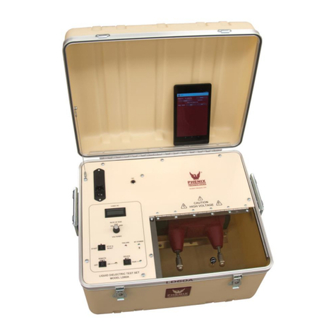
Phenix LD60A User manual

Phenix
Phenix 635-5P User manual

Phenix
Phenix PM1A User manual

Phenix
Phenix 4100-10 User manual

Phenix
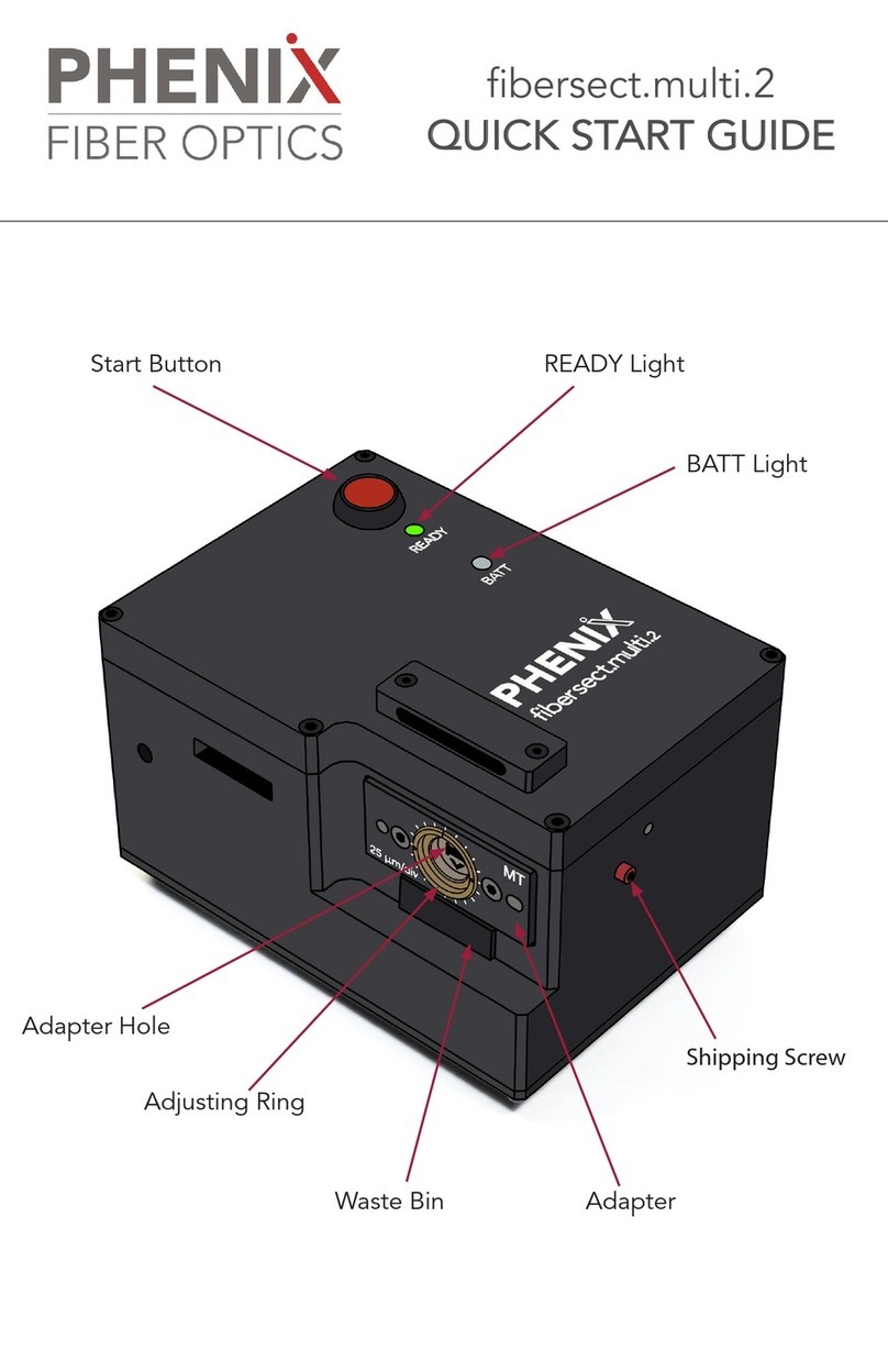
Phenix fibersect.multi.2 User manual

Phenix
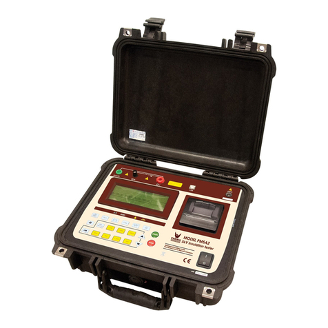
Phenix PM5A2 User manual

Phenix
Phenix 18450 Series User manual