Phenix PM5A2 User manual

1
PM5A2
PM5A2
5kV Insulation Tester
User’s Manual
Phenix Technologies, Inc
75 Speicher Drive
Accident, Maryland 21520
Tel: 1 (301) 746-8118
Fax: 1 (301) 895-5570
E-mail: info@phenixtech.com
Rev 3/2017
(GU-1547RB)
© 2016 Phenix Technologies, Inc. All rights reserved.

2
PM5A2
Safety Warnings
Read and understand all Safety Warnings and instructions in this User’s Manual before using this
instrument.
Observe safety procedures and rules for working near energized high voltage systems during the use
of this equipment. The generated voltages may be dangerous.
Do not connect or disconnect the test leads during the measurement.
Be careful not to create short-circuit between the terminals while a measurement is running, because it
could be dangerous for the operator.
Be sure that there are not any voltage difference between the points to which the equipment will be
connected to, neither between them and ground.
The panel, terminals, and connectors of the equipment must stay dry and clean.
This equipment should be used only by a trained and
competent person, strictly applying suitable safety
rules.
Symbols Used
Caution, risk of electric shock.
Caution, refer to User Guide.
Battery
Printer
Capacitance
Voltmeter
Equipment complies with current EU Directives.
The rubbish bin with a line through it means that in the European Union,
the product must undergo selective disposal for the recycling of electric
and electronic material, in compliance with Directive WEEE 2002/96/EC.

3
PM5A2
Contents
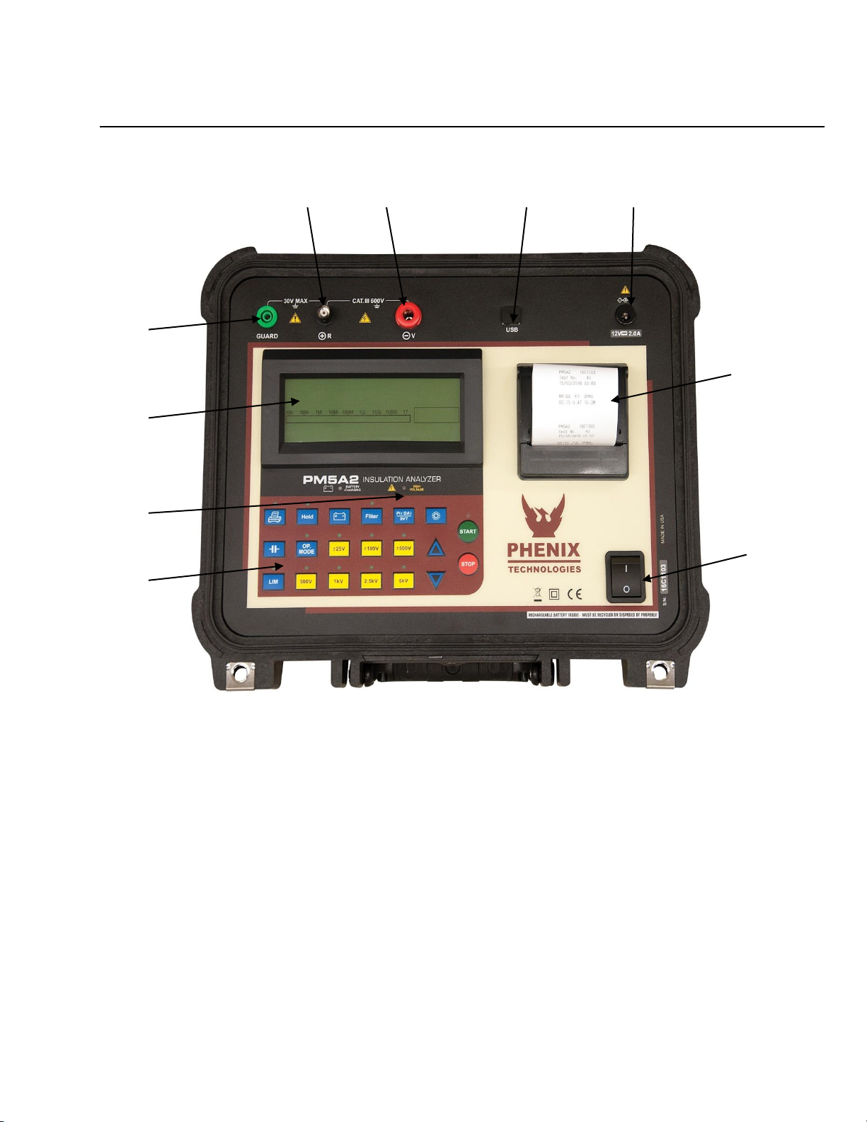
1. Description........................................................................................................ 4
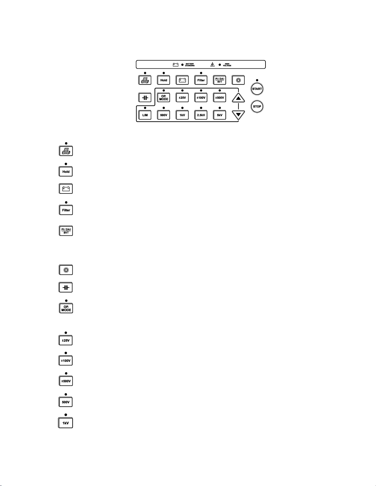
2. Panel control functions ..................................................................................... 5
2.1. Keyboard.................................................................................................... 6
2.2. Display....................................................................................................... 7
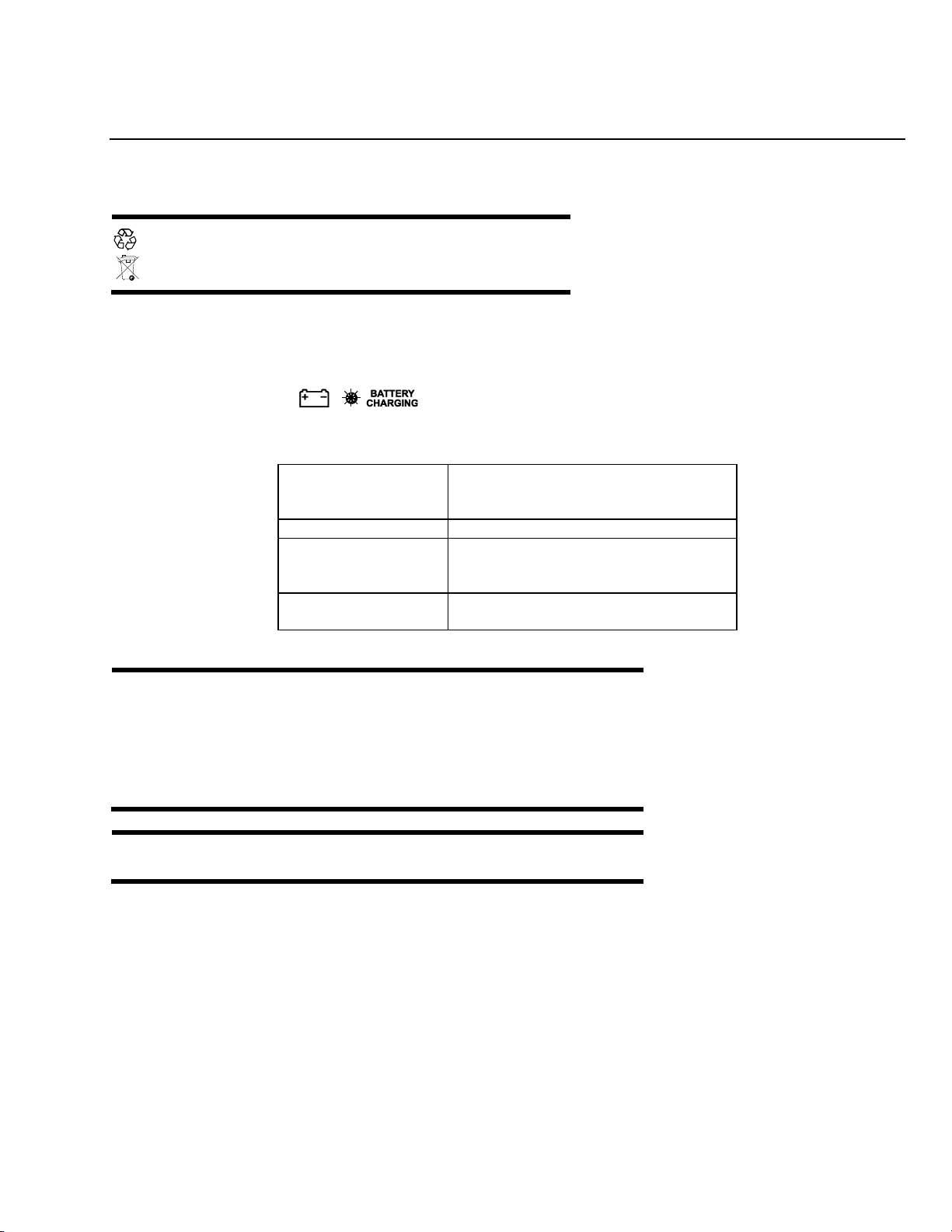
3. Charging battery ............................................................................................... 8
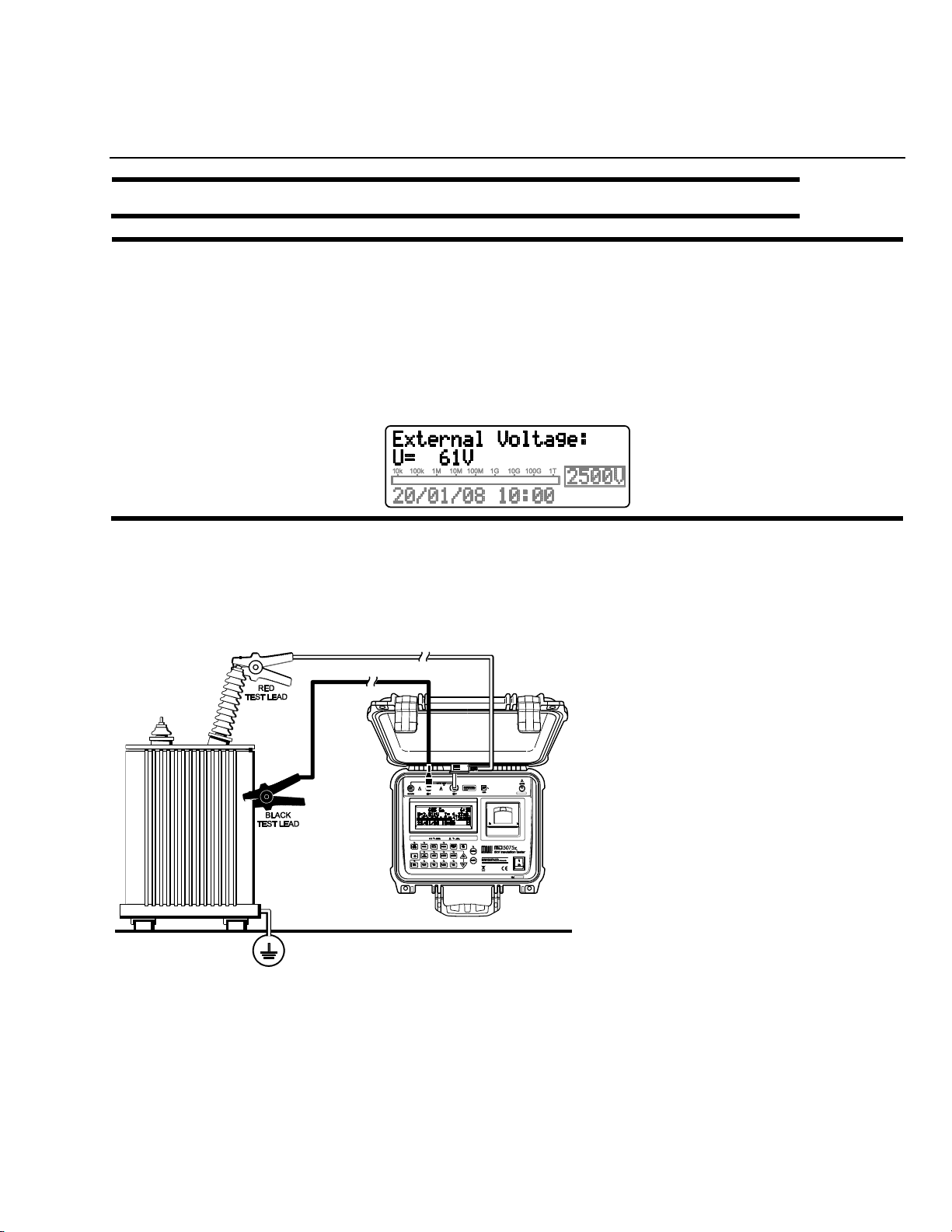
4. Connecting the PM5A2 ..................................................................................... 9
5. Use of “Guard” (G) terminal ........................................................................... 10
6. Setting tests .................................................................................................... 11
6.1. Test voltage definition............................................................................... 11
6.2. Selection of the operation mode ............................................................... 11
6.2.1. Normal mode........................................ Error! Bookmark not defined.
6.2.2. SVT Mode (step voltage tests)........................................................... 12
6.2.3.TIMER Mode....................................................................................... 13
6.2.4. Pass / Fail Test mode ........................................................................ 13
7. How to perform tests...................................................................................... 14
7.1. Measurement of the Dielectric Absorption Index (DAI).............................. 15
7.2. Measurement of the Polarization Index (PI).............................................. 15
8. Other functions............................................................................................... 16
8.1. Backlight................................................................................................... 16
8.2. Filter......................................................................................................... 16
8.3. True RMS AC/DC Voltmeter..................................................................... 16
8.4. Leakage current measurement................................................................. 16
8.5. Capacitance measurement....................................................................... 16
8.6. Hold.......................................................................................................... 17
8.7. Internal memory ....................................................................................... 17
8.8. Battery status check................................................................................. 17
8.9. Auto power-off.......................................................................................... 17
9. Software.......................................................................................................... 18
9.1. USB Drivers.............................................................................................. 18
9.1. MegaLogg2 software................................................................................ 18
10. Printer ........................................................................................................... 19
11. Cleaning ........................................................................................................ 19
12. Technical specifications ................................................................................ 20
13. Application note 32....................................................................................... 22
14. Customer Comments / Suggestions.............................................................. 24

4
PM5A2
1. Description
The digital insulation tester model PM5A2 is an advanced insulation analyzer, and it is one of the more complete and
sophisticated on the international market. It uses an efficient, carefully tested technology, which provides safe, reliable, and
accurate measurements of insulation resistances up to 5 TΩ, with 4 preselected test voltages: 500 V –1 kV -2.5 kV –5 kV.
Other test voltages may be selected in steps of 25 V, 100 V, or 500 V.
A microprocessor controls the equipment, making the operation easier and enabling the incorporation of advanced features
such as:
Auto-range selection
Memory enables storing up to 4000 readings
AC/DC voltmeter
Polarization and Dielectric absorption index automatic measurement, Measurement of Leakage Current and Capacitance
TIMER to program resistance test time
“Limit” to allow making test type Pass / Fail with programmable limits Step Voltage Test
Built-in Printer
Real Time Clock and Calendar for measurement identification
Built-in chronometer, indicating elapsed time, in minutes and seconds, since the test started.
The USB interface enables communication of the equipment with a computer to transmit registered data. The MegaLogg2
software analyzes the results and displays through charts and tables, automatically generating the test protocol. The built-in
printer records values on paper every 15 seconds.
Due to its constructive features, this instrument delivers an excellent performance both with laboratory and field work, under
difficult environmental conditions.

5
PM5A2
2. Control Panel Functions
1. Voltage Output Terminal (-V)
2. Zero Reference Terminal (+R)
3. Guard (G) Terminal
4. Display Screen
5. High Voltage LED
6. Keyboard
7. On / Off Key
8. USB Communication Port
9. Power Supply Input
10. Printer
8
9
10
7
1
2
3
4
5
6

6
PM5A2
2.1. Keyboard
Key
Function
LED
Turns the printer on/off
Indicates that the
printer is turned on.
Hold - Freeze the last reading on
the display
The Hold function is on
Battery - exhibits the battery
charge status on the display
Indicates that the
battery charger is on
Filter - Activates the filter that
minimizes the interferences of the
external noise
Indicates that the filter
is on
Shows the calculated value on the
display as a result of a Step Voltage
Test (SVT), Polarization Index (PI),
and Dielectric Absorption Index
(DAI)
–
Backlight - activates the display
light
–
Capacitance–displays the
capacitance value
–
Activated enables the programming
of the Operation Mode (Normal,
SVT or with TIMER of selectable
time)
Indicates that the
selection of the
Operation Mode is
enabled
Activated, enables programming of
25 V step tests voltages
25 V steps activated
Activated, enables programming of
100 V step tests voltages
100 V steps activated
Activated, enables programming of
500 V step tests voltages
500 V steps activated
Selection of 500 V test voltage
Indicates 500 V
selected
Selection of 1 kV test voltage
Indicates 1 kV selected

7
PM5A2
Keyboard (Cont’d)
KEY
FUNCTION
LED
Selection of 2.5 kV test voltage
Indicates 2.5 kV
selected
Selection of 5 kV test voltage
Indicates 5 kV selected
These keys (decrease or increase)
enable the selection of the value
that is being programmed.
–
Activates / enables programming of
the limit for the “Pass / Fail” test
Indicates when the
measured resistance is
lower than programmed
limit
Start - Start test
Indicates that the test is
being executed
Stop - End of test
–
2.2. Display
Measurement results in the corresponding measuring unit, elapsed time since the measurement started, selected
test voltage, analog indication by means of a bar graph, and several messages to the operator are displayed on
alphanumeric LCD.

8
PM5A2
3. Charging Battery
The PM5A2 uses a rechargeable LiFePO4 12 V –6000 mAh.
At the end of battery useful life, the battery must be recycled
or disposed of properly, in order to protect the environment.
Charging Procedure:
Check if the PM5A2 is turned-off and connect it to the mains (AC adapter).
The charging indicator ( ) will turn on red and will remain that way until the battery is fully
charged. The light will remain green and stay that way until the PM5A2 is disconnected from the mains.
Alternate green and
red lights
Evaluation of the battery initial status
when the source is connected, during
one second.
Steady red light
Battery under charge.
Flashing red light
The battery was not successfully
charged. It denotes some trouble in the
battery charging process.
Steady green light
The charge has successfully finished.
The battery is OK.
The rechargeable battery does not have “memory effect;” there are no
restrictions to start charging it as many times as is needed. However, the
battery could be damaged if it remains in deep discharge for a while.
To avoid this effect, charge the battery before placing the equipment in
storage and recharge within 30 days, even if the instrument wasn’t used
(when stored, the battery loses part of its charge).
IMPORTANT: While the equipment is connected to the mains supply, the
START key is inhibited; measurements cannot be made.

9
PM5A2
4. Connecting the PM5A2
ATTENTION: For safe operation, follow the procedures detailed below with the device Powered-Off.
Check if there is no difference of potential voltages between the points where the PM5A2shall be connected to.
Also, check the same between those points and the ground.
At the time of the connection and power-on, the equipment automatically enters in the
voltmeter mode and displays the circuit voltage.
The circuit to be tested must be de-energized to avoid interferences in the measurement. The equipment will block
the start of measurement if it detects a voltage greater than 60 V in the circuit.
Connect the red cable security terminal to the equipment (-V) output terminal, the BNC terminal of the black cable
to the zero reference (+R) terminal and the “alligator” terminals to the element to be measured as indicated in the
figure.
The test leads in the picture are merely illustrative.

10
PM5A2
5. Use of “Guard” (G) Terminal
Depending on the measurement to be made, the Guard (G) may be used or not. During the measurements, the
equipment should be electrically grounded to avoid unsteady readings. When insulation is measured regarding
grounding, the Rterminal is connected to earth and the condition by means of which the equipment potential
setting is fulfilled. If the measurement is performed between two parts, which are not grounded (for example,
between two phase conductors in a three-phase cable), the equipment GUARD terminal must be grounded. This
implies that whenever a measurement is performed, one of the GUARD or R terminals must be grounded,
but not both of them simultaneously.
Technical Note 32, reproduced at the end of the manual, explains the usage of GUARD terminal in order to
eliminate the unwanted resistance effect over the result of measurements.

11
PM5A2
6. Setting Tests
The PM5A2 insulation tester is an extremely versatile instrument that enables automatic performance of several
types of insulation tests, and records them in its internal memory and/or prints the results. Thus, it is necessary to
define the tests to be performed, setting the following parameters before starting the measurement: Test voltage,
Test duration for “TIMER” mode test, Maximum Voltage for step voltage test (SVT), and Minimum resistance limit
for “Pass/ Fail” tests.
6.1. Test Voltage Definition
In order to define the test voltage value, first it is necessary to select one of the voltage adjustment keys:
. These keys enable both the pre-programmed voltage selection ( ) and the and keys
that increase or decrease the value of the step voltage test for 25 V, 100 V or 500 V, depending on the selected
voltage adjustment key.
As long as the equipment is on, the voltage adjustment key will be selected. Press the adjustment key
selected again at the moment when leaving the test voltage selection mode.
Note: Test voltage is the only one parameter that may be modified during tests.
6.2. Selection of the Operation Mode
The PM5A2 insulation tester has four operation modes: Normal, with TIMER, SVT, and Pass / Fail. The first three
modes are selected using the key; the “Pass/ Fail” test mode is activated pressing key.
6.2.1 Normal Mode
The normal mode is used in the resistance measurement with unique voltage, without time limit. When selected,
there are no special indications in the display.

12
PM5A2
6.2.2 SVT Mode (step voltage tests)
The use of key allows the PM5A2 setting for the performance of a step voltage test; when this mode is
selected, the display shows the SVT abbreviation.
Under this operation mode, the user does not define a specific voltage test, but a maximum voltage value. The
device will start the test applying a 500 V voltage and increase this value in 500 V steps each minute until reaching
the programmed voltage. At each stage, the PM5A2 measures the resistance before advancing towards the
following step.
The use of voltage adjusting keys determines the value of the highest voltage –which will be, in all cases, a
multiple of 500 V, up to a 5000 V limit. It is advisable to use the key in order to select this value; and
keys may be used, but if the selected value is not a multiple of 500, it will be rounded down.
The test result is calculated according to the following formula:
=
SVT R
R
V MAX
500
After test ends, the value may be recovered by pressing key.

13
PM5A2
6.2.3 TIMER Mode
The use of key allows the PM5A2 setting for the performance of a pre-set - duration test. When this mode is
selected, the display shows the programmed time. Use and keys to define the duration of the tests in 1
minute, 3 minutes, 10 minutes, 30 minutes or 90 minutes.
6.2.4 Pass / Fail Test mode
Press key in order to determine the lower insulation limit for type “Pass / Fail” test. Select this value using
and keys. Possible values are 10 MΩ, 100 MΩ, 1 GΩor 10 GΩ.
During a Pass/ Fail test, the PM5A2 will indicate when the insulation resistance is lower than the programmed limit,
both with an intermittent beep and the key led flashing. The key LED will remain flashing until the end of
tests, or until the measurement of the resistance value is greater than the programmed limit.

14
PM5A2
7. How to Perform Tests
After having set the desired measurement, press
key. The HIGH VOLTAGE indicator will turn on
indicating that the insulation tester is applying high
voltage to the element under test.
Then, the intelligent auto-range system will search for the most convenient range for the value under measure. At
this moment the display will show the message “WAIT...”.
As soon as the unit selects the appropriate range, the display will show the number of test, the selected voltage
value, displaying the value of the applied voltage and the leakage current. The unit records date and time, starts
counting the elapsed time and the resistance value indication will be displayed with its corresponding unit, and the
analog indication will start by bargraph.In order to end the test, press the key. At that moment, the last
measured values will remain frozen in the PM5A2 display. By pressing the key again, the equipment will return
to the voltmeter function.
Example:
The display exhibits the test number (12), the measured resistance value (602 GΩ, the voltage selected of 2500
V, the elapsed time (6:25 minutes), the applied voltage (2.51 kV), the leakage current (4.17nA), and date and time.
NOTE: If the resistance measured is greater than 5 TΩ@ 5 kV, the following message will be
exhibited: R > 5TΩ
WARNING: Never connect or disconnect the test leads with the equipment under operation or while the High
Voltage LED is on. If there is a need to modify the connections, this should be done with the equipment
disconnected and with discharged potentials (High Voltage LED off)

15
PM5A2
7.1. Measurement of the Dielectric Absorption Index (DAI)
When pressing the key during the test, the Dielectric Absorption Index (DAI) value will be exhibited on the
display. It is only possible to apply this function after a minimum of 1 minute of measurement; in case the key is
pressed before this minimum limit, the display will show the message of value exhibition of DAI value, but will not
show any value.
The DAI index is the quotient between the values of the insulation resistance measured at the 60 and 30 second,
and it is useful for preventive and predictive maintenance of windings (present in transformers, motors, generators,
etc.).
=
DAI R
R
60seconds
30seconds
7.2. Measurement of the Polarization Index (PI)
When pressing the key during the test, the Polarization Index (PI) value will be exhibited on the display. It is
only possible to apply this function after a minimum of 10 minutes of measurement. If the key is pressed before this
minimum limit, the display will show the message of PI value, but will not show any other values.
The polarization index is the quotient between the values of the insulation resistance measured both in 10 minutes
and 1 minute. This index is useful to detect the damage of the insulation resistance by the excessive presence of
dust, dirt and greases or through the action of chemical and physical agents.
=
PI R
R
10minutes
1minute

16
PM5A2
8. Other Functions
8.1. Backlight
The equipment display has a backlight. To activate it, press key. After 10 seconds the backlight will turn off. To
reactivate it, press key again.
8.2. Filter
When insulation measurements are carried out in transformers or in large dimension machines in presence of
strong electromagnetic fields, it is possible for the equipment reading to be unstable, especially for resistance
values higher than 100 MΩ. In these cases it is convenient to press the key before starting the measurement
activating the filter that allows for the reaching of the insulation resistance value in an upward curve without
significant oscillation.
8.3. True RMS AC/DC Voltmeter
In order to use this function, connect the test points and turn on the unit. The measured value will be exhibited
automatically in the display.
AC
DC
10V up to
1000Vr.m.s.
10V up to 1000V
Precision: ± (5% of the reading + 3 digits)
8.4. Leakage current measurement
During the tests, the equipment measures and displays the leakage current value within a range of 1 nA up to
3 mA, with a precision of ± (10% of the reading + 3 digits).
8.5. Capacitance Measurement
The capacitance value is obtained by measuring the insulation resistance. After finishing measuring (When the
key has been pressed), wait until the high voltage LED turns off, and press the key and the capacitance value
will be exhibited on the display.
Voltage
Capacitance
500V
50nF up to 10µF
1,000V
50nF up to 5µF
2,500V
30nF up to 2µF
5,000V
30nF up to 1µF
Precision: ± 10% of the measured value ± 3 digits
Note: “0” will be exhibited on the display when measuring values lower than 50nF

17
PM5A2
8.5. Hold
This function allows holding the last performed reading on the display at the moment when pressing the key,
without interrupting the test. When this key is pressed again, the equipment updates the resistance and
chronometer values. The led of key and the letter Hon the display indicate that the function has been
activated
8.6. Internal memory
This equipment has an internal memory for up to 4000 measured values(approx. 280 DAI tests or 30 PI tests). This
memory is controlled by the instrument and works in a cyclic way. When the memory is full, the oldest values in the
memory will be replaced by the newest ones. To avoid loss of data, always download the internal memory after
finishing the measurements.
8.7. Battery status check
Press and hold the key in order to check the battery status during measurements. The analog bar graph will
give an approximate visual representation of the remaining charge percentage; additionally, the display will show
the message “Battery OK” if the charge is enough, or “Battery Low” if the charge is low. In this last case, it is
highly advisable to charge the battery before using the apparatus. If the battery charge is under 20% of the total,
the message Battery Low will automatically appear on the display.
8.8. Auto power-off
The PM5A2 auto-turns off after 10 minutes of inactivity, or after 95 minutes of measuring without checking the
battery status.

18
PM5A2
9. Software
9.1. USB Drivers
To install the USB drivers required for the communication between PC and equipment, use the following
instructions:
1. Connect the equipment to the PC using the USB cable.
2. If there is an available Internet connection, Windows will automatically connect to the Windows Update website
and install any suitable driver it finds for the device. If no suitable driver is automatically found, then insert the
CD-ROM supplied with the equipment in the PC, run the executable “usb-install.exe” and click “Install.”
9.1. MegaLogg2 software
This software makes communication between the equipment and a computer with Windows operative system
easier. It synchronizes the date and time of the equipment internal clock with the computer date and clock, to
transfer the stored date, to clear the memory, to generate test graphics and protocols, etc. The installation and
operation instructions are included in the software.

19
PM5A2
10. Printer
To enable the printing function press key. Measured values will be printed each 15 seconds, and the
Dielectric Absorption Index and Polarization Index will be printed after 1 minute and 10 minutes respectively.
Printing may be started or stopped at any time during the test. However, it is convenient to turn the printer on
before starting the test in order to print it completely, including the heading.
CAUTION: Don’t pull the paper. The printer can be easily
damaged.
This printer uses 56mm-wide thermal paper, which comes in a 30mm-diameter reel.
Pull the lever located on the lid.
Insert the paper reel as shown in the figure.
Keep the tip of the paper out of the printer and close the lid.
11. Cleaning
The panel, terminals, and connectors of the equipment must stay dry and clean. Cleaning should be made using a
soft detergent or isopropyl alcohol (be sure that the products to be used for cleaning do not affect plastic goods).

20
PM5A2
12. Technical Specifications
Test voltages
:
500 - 1,000 - 2,500 - 5,000 V with fast
selection.
From 500V to 5kV selectable in 25V,
100V or 500V steps. DC, negative in
relation to grounding.
Maximum resistance
reading
:
5TΩ @ 5kV
DC Voltmeter
:
10V up to 1000Vdc
Precision: ± (5% of the reading + 3
digits)
AC voltmeter
:
10V up to 1000V rms.
Precision: ± (5% of the reading + 3
digits)
Over voltage protection
:
CAT. III –600V
Current measurement
:
1nA up to 3mA
± (10% of the reading + 3 digits)
Capacitance
measurement
:
50nF up to 10µF @ 500V
50nF up to 5µF @ 1,000V
30nF up to 2µF @ 2,500V
30nF up to 1µF @ 5,000V
Precision: ± 10% of the reading ± 3
digits
Short circuit current
:
Max. 3mA
Display
:
Alphanumeric. It exhibits
measurements both in digital and
analog format by bargraph.
Test voltages accuracy
:
± 3% of nominal value over a 10GΩ
resistance
Equipment accuracy
:
±5% of reading between 1MΩ and
1TΩ @ 5kV
±20% of reading between 1TΩ and
5TΩ @ 5kV
(For lower test voltages, the superior
limit is proportionally reduced)
±20% of the reading between 10kΩ
and 100kΩ
±10% of the reading between 10kΩ
and 1MΩ
Table of contents
Other Phenix Test Equipment manuals
Popular Test Equipment manuals by other brands

JDS Uniphase
JDS Uniphase Portable Optical Tes Platforms MTS-6000 Specifications

PCE Instruments
PCE Instruments PCE-CRC 10 user manual

Fluke
Fluke 700PA3 instruction sheet

Seica
Seica VIP PILOT V8 Operator's manual

Thermo Electron
Thermo Electron Orion AQUAfast II Quick start card

Ametek
Ametek T Series Operation manual