Phenix 4100-10 User manual

DCD 4100-10
USER’S MANUAL
DC DIELECTRIC TEST SET - 400P
MODEL 4100-10
VERSION 5.2
Phenix Technologies Inc.
75 Speicher Drive
Accident, MD 21520
Copyright © Phenix Technologies, Inc
Rev 5/28/2015 nab

INTRODUCTION
The DC Hipot line offered by Phenix Technologies is ruggedly built and suitable for field or
lab use. It is designed to test electrical switchgear, cables, motors, generators, and
protective equipment. DC testing is popular because the equipment is more compact and
lighter in weight than comparable AC equipment.
Design and Safety Features
Output voltage continuously adjustable to 100kV DC.
“Zero Start” voltage interlock and external safety interlock.
Leakage current measurements available from .01 to 20,000 microamps DC.
Removable line cord.
Rotary switch selection simplifies operation.
Integrated cable storage bin.
Built in discharge circuit rated at 6 kilojoules.
Light weight, portable, and enclosed in rugged, high-density polyethylene carrying case.
Adjustable overcurrent trip point from 10%-110% of each range.
Large, easy to read LCD meters.
Input Circuit Breaker / Power Switch.
Thermal resettable overload protecting high voltage transformer primary circuits.
Very low ripple at normal hi-pot test impedances.
For full detailed specifications, see Section 1-1.

DCD 4100-10
TABLE OF CONTENTS
DESCRIPTION SECTION
INTRODUTION
DANGER / GENERAL SAFETY PRECAUTIONS
TECHNICAL SPECIFICATIONS 1
CONTROLS AND INDICATORS 2
ELECTRICAL SET-UP 3
OPERATING INSTRUCTIONS 4
RETURN-GROUND-GUARD FRONT PANEL CONNECTIONS 5
CALIBRATION 6
TROUBLESHOOTING 7
STORAGE OF EQUIPMENT 8
CIRCUIT DIAGRAM SYMBOLS 9
RECOMMENDED SPARE PARTS / PARTS LIST 10
PARTS ORDERING INFORMATION 11
RETURNED MATERIAL 12
ELECTRICAL DIAGRAMS 13

GENERAL SAFETY PRECAUTIONS
HIGH VOLTAGE
This equipment is capable of providing POTENTIALLY LETHAL VOLTAGES!
Improper operation or test practices may result in injury or death to the operator or
surrounding personnel.
The operation of High Voltage test equipment should only be performed by personnel
familiar with HIGH VOLTAGE testing and safety procedures. The operator of this
equipment must be aware of all hazards associated with High Voltage testing. The operator
is responsible for himself and others in close proximity of the testing area.
Some General Safety Practices for working with High Voltage Test Equipment have been
listed below for your reference.
Become familiar with your instrument before performing an actual test.
Know your work area, check that all circuits are de-energized and locked out.
Never work alone; always work with another qualified worker.
Mark off entire work area with barriers and warning tape.
Make all personnel aware of your testing activities.
Be aware of dangerous conditions that may arise from energizing a test specimen.
Never modify test equipment, modifications to equipment could introduce an
unknown hazard or hinder a designed-in safety feature.
DO NOT operate damaged equipment. Remove power, and do not use the
equipment until safe operation can be verified by service-trained personnel.
Phenix Technologies, Inc. assumes no liability for unsafe or improper use of test
equipment.

DCD 4100-10
1-1
SECTION 1: TECHNICAL SPECIFICATIONS
Input
120 VAC 10 Amps or 220 VAC 5 Amps, 50/60 Hz, single phase (refer to Unit Data Tag)
Output Rating (maximum)
0-100 kilovolts dc
0-5 milliamperes continuous resistive leakage
0-20 milliamperes short term capacitive charging
Internal Discharge Capability 6 kilojoules
Duty Cycle
Continuous –Capacitive Charging
Type of Cooling Natural convection.
Ripple Less than 2 percent RMS at loads of 30 Megohms and higher from 10kV-100KV and
capacitive loads.
Output Negative output, positive ground standard. Positive output available by special order. Filtered voltage
doubler circuit, equivalent to full wave rectification.
Operating Ambient Temperature 0 to 35 degrees Celsius.
Output Termination High voltage cable, shield guarded.
Metering
Output Voltmeter: 3 ½ DIGIT LCD, accuracy .5% of full scale.
Ranges: 0 to 19.99kV, 0-100.0kV
Output Currentmeter: 3 ½ DIGIT LCD, accuracy .5% of full scale.
Ranges of 0 to 19.99a, 199.9A, 1.999mA, 19.99mA
Analog Output 1.5” ANALOG
Charging Indicator: 0-100% of selected range indication.
Size and Weight
22.5" W x 21" D x 16.5" H; 98* lbs. (572 mm W x 533 mm D x 419 mm H; 44.5* kg)
*For 220 V units: add 10 lbs. (4.5 kg)

2-1
SECTION 2: CONTROLS AND INDICATORS
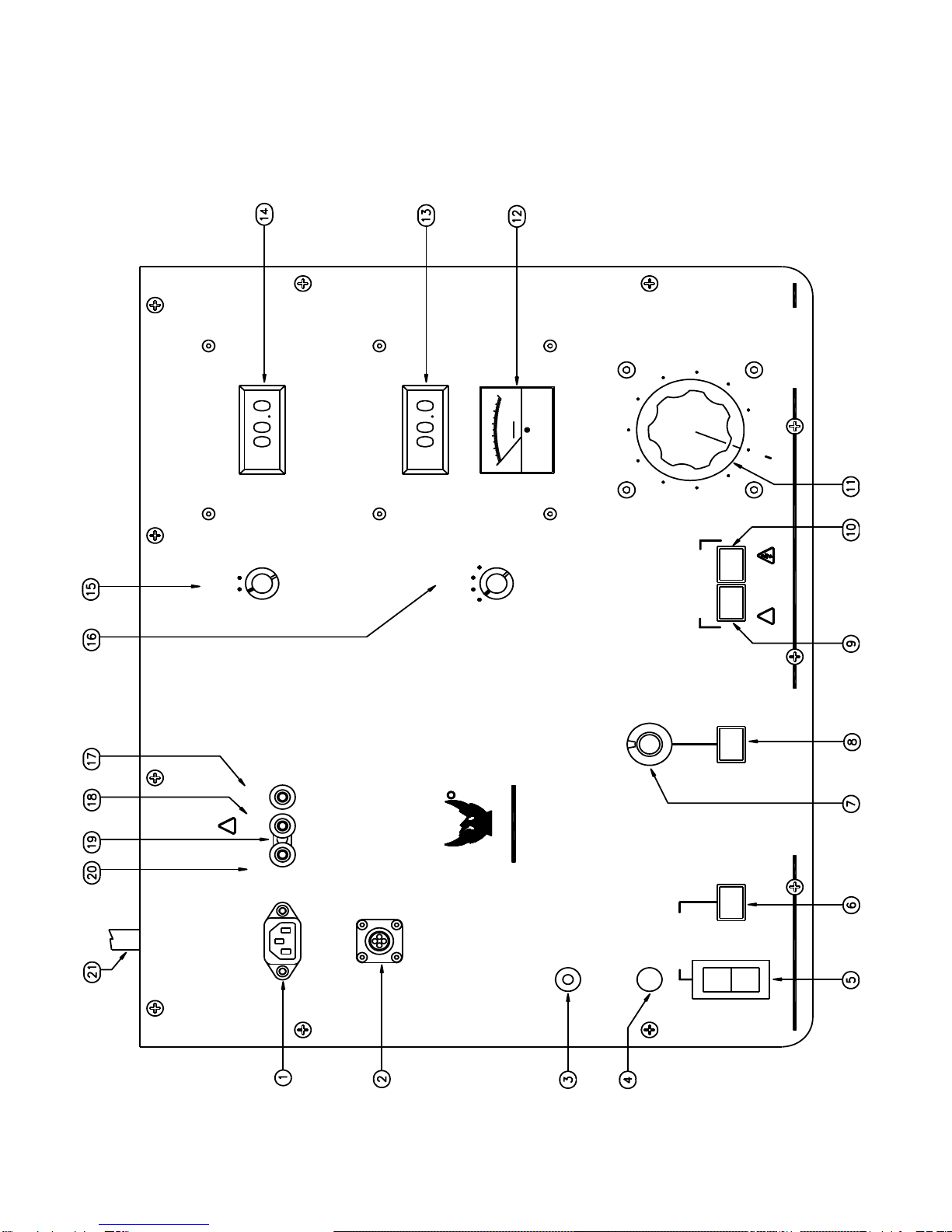
CONTROL PANEL
(Refer to Figure 2-1).
1. AC POWER INPUT. Plug into a suitable grounded receptacle. See specifications tag on unit for voltage
and current requirements.
2. EXTERNAL INTERLOCK. If desired, remove jumper from connector and replace with contact(s) that must
be maintained closed during testing. Some examples include footswitch, deadman switch, gate interlock,
panic button, etc.
3. THERMAL OVERLOAD. Circuit breaker protects primary of high voltage transformer. If circuit breaker
trips, turn High Voltage off and return Voltage Control knob to zero before resetting.
4. F1. Control Power Fuse.
5. MAIN POWER CIRCUIT BREAKER. Press Ito connect power, Press Oto disconnect power.
6. MAIN POWER INDICATOR. Lights to indicate that power is available for testing.
7. Current Trip Adjust. Dial adjusts from 1 to 11 corresponding to approximately 10% to 110% of selected
output current range. Current Trip/Reset lamp illuminates and high voltage turns off when output current
exceeds setting, causing circuit to trip. Circuit also acts as short circuit and overload protection on high
voltage output. To reactivate high voltage, Voltage Control must be returned to zero, and Reset switch
must be pressed to clear Current Trip circuit.
8. Reset. Reset lamp illuminates to show that current trip circuit has tripped. High voltage circuits are
deactivated. Momentary Reset switch must be pressed to extinguish Reset lamp to allow high voltage to
be reapplied after returning Voltage Control to zero.
9. High Voltage On. Press to turn on high voltage.
Conditions required before high voltage will activate are:
Voltage control at Zero Start
External Interlock loop closed.
Current Trip circuit Reset.
10. High Voltage Off. Press to turn off high voltage output. Under normal circumstances the voltage control
should be returned to zero, and the high voltage allowed to decay near zero before switching High Voltage
OFF.
CAUTION: Capacitive loads may retain voltage for a short time after high voltage is turned off
while the internal circuitry bleeds their charge to ground. High Voltage Off lamp must be illuminated
before High Voltage ON can be activated. Conditions required for illumination are:
External Interlock loop must be closed.
Overcurrent Trip/Reset circuit must not be tripped. (Push Reset if circuit is tripped)

DCD 4100-10
2-2
CONTROLS AND INDICATORS
CONTROL PANEL (Cont’d)
11. Output Voltage Control. Turn clockwise to increase output of test set. This control must be in the full
counter-clockwise position (Zero Start) in order to turn High Voltage On. Under normal circumstances,
Voltage Control should always be returned to zero and voltage displayed on the voltmeter allowed to
decay to zero before pressing High Voltage Off.
12. ANALOG CURRENT INDICATOR. Meter displays current from 0-100% of range to give visual indications
of capacitive charging conditions or to show changing current conditions that are not easily determined
from digital meters.
13. CURRENTMETER. Displays current out of High Voltage Lead (#16) or into Return terminal depending
upon mode of measurement
14. VOLTMETER. Displays voltage output of test set in kilovolts.
15. VOLTMETER RANGE SELECTOR. Rotate to appropriate setting for test voltage.
16. CURRENTMETER RANGE SELECTOR. Rotate to desired range. With capacitive loads, selector will
normally be placed in highest current range and then ranged lower as appropriate.
17. GUARD TERMINAL. Connect to Ground terminal (#13) with Grounding Clip for Guard Mode operation.
Connect currents that need to bypass the currentmeter to this point. Low potential side of specimen must
be isolated from ground to use this mode, and will be connected to Return post. See section on
Return –Ground –Guard for more information.
18. GROUND (GND) TERMINAL. Connects to facility ground. See (#12), (#14) and (#15) for more
information.
19. GROUNDING CLIP. The Grounding Clip must always be connected from the Ground post to either the
Return post or the Guard post. Do not operate the unit with the clip disconnected.
See Section 5 on Return –Ground –Guard for more information.
20. RETURN (RTN) TERMINAL. Connect to Ground terminal (#13) with grounding clip for normal operation.
Always connect low potential side of test specimen to this point. This is the metered connection point for
measuring current. This mode must be used if low potential side of test object is grounded or has a ground
reference. See section on Return –Ground –Guard for more
information.
21. HV OUTPUT LEAD. This lead is always attached to the high potential side of the specimen under test.

2-3
CONTROLS AND INDICATORS
FIGURE 2-1
PHENIX
TECHNO LOGIES
TECHNOLOGIES
PHENIX

DCD 4100-10
3-1
SECTION 3: ELECTRICAL SET-UP
High Voltage Connection
1. Locate the desired placement for the test set. Prepare the main power input cable for plugging into the
proper facility power (i.e., 120 volts AC or 220 volts AC). Leave plug unconnected at this time.
2. Place currentmeter in desired mode of operation by connecting the jumper clip between Return (RTN) and
Ground (GND) or Guard (GRD) and Ground (GND) binding posts. The normal connection is between
Ground and Return. See Section 5 on Return-Ground-Guard for more information on this connection.
3. Connect the Ground (GND)” connection to facility ground using the ground test lead provided.
4. Connect the low potential side of test specimen to terminal labeled Return (RTN). Use red test lead
provided.
5. Connect the high voltage output cable to the high potential side of test specimen. CAUTION: Keep
shielded part of high voltage cable away from test specimen high voltage points.
6. Connect the input main power cable to appropriate power source. Check Technical Specifications tag on
unit, for proper input voltage.
7. Read and understand entire operating instructions before applying power.
WARNING:
Main Power switch on front panel must be in the OFF (O) position before proceeding. Make sure
Test object is de-energized and discharged.
WARNING:
Improper contact with the test leads on this equipment can cause harmful or fatal electrical shock.
Do not touch test leads while a test is in process. This equipment should only be operated by
someone familiar with high voltage testing and safety procedures.

4-1
SECTION 4: OPERATING INSTRUCTIONS
1. Ensure proper electrical set-up has been performed.
2. Check that the Voltage Control dial is set to "0" (Zero Start position).
3. Select the proper voltmeter range, currentmeter range, and current trip setting.
High Voltage Applied
4. Turn on the Control Main Power switch. The Power On lamp will illuminate.
5. Momentarily press the HV On pushbutton. The high voltage will be applied to the cable and the HV On
switch lamp will illuminate. (Zero Start and External Interlock Loop conditions must be met, and Reset
lamp must be extinguished.
6. With HV On, rotate the Voltage Control dial and watch the Output Voltmeter and Output Currentmeter
until desired levels are reached.
Note: When testing samples that are largely capacitive in nature, it may be necessary to place
currentmeter range switch in the 20mA position. Operator must then slowly raise output watching the
currentmeter and allowing the test sample to "charge up".
7. Record data, if desired, and lower the Voltage Control to Zero after testing is completed. Use Discharge
or Grounding stick to discharge specimen or allow voltage to return to zero. Press HV Off button; high
voltage will be shut off and the HV (On) switch lamp will extinguish and the High Voltage Off/Ready lamp
will illuminate.
Overcurrent Failure
8. If an overcurrent situation occurs (output current exceeds Overcurrent Trip setpoint), the over-current
relay will activate, de-energizing the test set (High Voltage Off). To regain high voltage the Reset button
must be depressed and, the Voltage Control dial must be returned to zero. Press the HV On button
momentarily to turn High Voltage back on.
9. After all testing is completed; turn off the front panel Main Power switch. Remove the input power cable
from the facility power input.
10. CAUTION: Make certain that the test specimen is totally discharged and grounded before
removing test cables.
WARNING:
This equipment should only be operated by personnel familiar with high voltage testing and safety
procedures. Improper operation may result in injury or death and can cause damage to the unit or
test object.

DCD 4100-10
4-2
OPERATING INSTRUCTIONS
Calculating Meg-Ohms The Impedance of a test object can be determined by the formula :
V/I=R where voltage in Volts divided by current in Amps equals Resistance in Ohms.
Resistance divided by 1,000,000 then equals Meg-Ohms: R/1,000,000=Meg-Ohms
When voltages are in Kilovolts and currents are in Milliamps, a more direct method is to directly divide
Kilovolts by Milliamps to obtain the result directly in Meg-Ohms.
KV/mA=Meg-Ohms
Example: 10kv divided by 2mA equals 5Meg-Ohms
Many times though, the current will be in micro amps. In this case, micro amps must first be converted to
milliamps, or the formula must be changed to accommodate micro amps.
Micro amps can be converted to milliamps by dividing by 1,000.
uA/1,000=mA Example: 50 uA/1,000=0.05mA. The result can now be used directly in the above
formula. 10kV divided by .05mA equals 200Meg-Ohms
An alternate method is to use the formula; Kilovolts divided by Microamps multiplied by 1,000 equals Meg-
Ohms.
KV/uA x 1,000=Meg-Ohms
Example: 10kV divided by 50uA times 1,000 equals 200Meg-Ohms

5-1
SECTION 5: RETURN-GROUND-GUARD CONNECTIONS
The unit contains a currentmeter feature useful in measurement of different current sources.
1. Return Mode (RTN) (Grounded Return Mode)
This is the standard measurement configuration. The Ground jumper is installed between the Ground
(GND) post and the Return (RTN) post. The low potential side of the test specimen is connected to
Return. It can initially be isolated from ground or tied to ground. When it is connected to Return in this
mode, it will be grounded through the Ground jumper if it was initially isolated from ground. This mode
measures all output current from the test set.
If the low potential side of the test specimen will not or can not be isolated from ground, Return mode is the
hookup mode that must be used. Any connections made to Guard must be isolated from ground in this
mode and will bypass the currentmeter. All currents to Ground and Return will be measured in this mode.
2. Guard Mode
In this mode, the Ground jumper is connected to the Guard post and Ground post. The low potential side
of the test specimen must be isolated from ground and connected to the Return post. Only current to the
Return post will be measured by the currentmeter. Any stray leakage currents to ground or from sources
connected to Guard will bypass the currentmeter and not be measured such as stray leakage currents to
ground, stray currents to shields or
housings tied to Ground or Guard, etc. In this mode, the low potential side of the specimen must be
isolated from ground. If the low potential side of the specimen can not or will not be isolated from ground,
this mode can not be used to accurately measure current flow.
NOTE: Do not operate unit with the ground jumper removed or not connected to either Return or Guard.
Make sure the Ground post is connected to a good earth ground. See connection diagrams (Figure 5-1)
on next page.

DCD 4100-10
5-2
RETURN-GROUND-GUARD CONNECTIONS
Figure 5-1

6-1
SECTION 6: CALIBRATION
All calibrations have been done at the factory. Periodic calibration of the output voltmeter and output
currentmeter should be done annually.
NOTE: Refer to Electrical Diagram Section for schematics pertaining to the model number of your test set.
Locating the Calibration Adjustments
The calibration points are shown in the following diagram.
1. Output Voltmeter
Connect a precision high voltage voltmeter across the output to ground on low range. Raise the output to
approximately 80% of range. Adjust the reading on the panel meter (M1) by means of potentiometer R1
to a corresponding reading. Check Linearity and calibration at various other main points of the range
such as 20%, 40%, 60%, 100%. Repeat for High range, adjusting R2.
R101
10%
Ovld
R103
110%
Ovld
R235
Range
Ovld
R201
20mA
CM
R202
2mA
CM
R203
200uA
CM
R204
20uA
CM
R2
100kV
VM
R1
20kV
VM
CAUTION:
Calibration should only be done by persons familiar with High Voltage testing and safety
procedures.

DCD 4100-10
6-2
CALIBRATION
2. Output Currentmeter
It is necessary to connect adequately rated High Voltage loads (isolated from ground) to the high voltage
unit that will allow each full range current to be drawn at approximately 15% or higher output voltage.
This allows sufficient resolution to adjust current levels.
Place Binding Post Configuration in GUARD MODE. (Jumper clip is installed between Guard and
Ground posts.)
Connect a precision ammeter between the low potential side of the appropriate high voltage load and the
Return post. Select the low current meter range (20uA). Raise the output to approximately 80% of
range (16uA). Adjust the reading on the panel meter (M1) by means of potentiometer R204 to the
corresponding reading of the standard meter. Repeat for 200uA, 2mA, and 20mA ranges; adjusting
R203, R202, and R201 respectively. (High Voltage load will need to change when changing range).
An optional method is to use DC current injection between “RTN” and “GND” (Guard Mode). If using this
method, do not turn High Voltage ON!
3. Overcurrent
This calibration should not need adjustment (factory adjusted). If the overcurrent circuit is out of
calibration, perform the following steps.
a. With unit off, short the output terminal to ground through an appropriate currentmeter. (A High
Voltage Load will give better resolution and make calibration easier and more accurate. Minimum
recommended resistance: 100K ohm, 100 watt.).
b. Set the Current Trip potentiometer on the front panel to "1”and the current range switch to 20mA.
c. Turn on HV On and adjust the output current slowly until 10% of rated current (2mA) is displayed on
the currentmeter.
d. Adjust potentiometer R101 until the Reset lamp illuminates and high voltage is shut off.
e. Set the Current Trip potentiometer on front panel to "11."
f. Turn on HV On and adjust the output current slowly until 110% of rated current (22mA) is displayed
on meter.
g. Adjust potentiometer R103 until the Overload lamp illuminates and high voltage is shut off.
h. Repeat steps "b" through "g" as necessary until both settings are calibrated.
4. Range Overcurrent. R235 sets an overcurrent for the ranges and should be set to trip at approximately
112% of 2mA range.

7-1
SECTION 7: TROUBLESHOOTING
General
If the controls do not operate properly after having been used according to the instructions, the following hints
may help.
Check main facility input power to the test set.
Check indicating lamps. (Spare lamps are available through Phenix Technologies.)
Check fuse-F1.
Check all external plug connections on the test set.
Specific Problems, Refer to appropriate electrical diagrams.
1. High Voltage cannot be turned on?
Voltage Control dial is not in Zero Start position.
External interlock circuit open.
Current Trip setting too low, or needs reset.
Current trip circuit damaged, won’t reset, try replacing U101 (LM311N)
Faulty HV On switch, faulty HV Off switch.
Relay K1 dislodged or faulty.
2. Voltage control inoperable?
Tripped or faulty Thermal Overload.
High voltage is not on (see number 1 above).
Faulty Variable transformer "T1".
Faulty High Voltage tank assembly.
3. Over current inoperable?
Faulty U101 (LM311N).
Faulty DC Power Supply circuit.
Defective over current relay K101.
Faulty R7 over current trip potentiometer.
4. Currentmeter inoperable?
Improper connection of GUARD/GND/RETURN jumper (J1) for mode of operation.
Improper connection of test specimen.
Faulty U201 or U202 (LM348).
Meter damaged.
Faulty currentmeter range switch SW5.
Faulty connection in currentmeter circuit.
Faulty DC Power Supply Circuit.
5. Voltmeter inoperable?
Meter damaged.
No high voltage present at output.
Faulty connection in voltmeter circuit.
6. No output voltage from high voltage section?
Defective metering circuit.
No input to voltage regulator section, possible problems with K1 relay or Thermal Overload.
High Voltage Cable shorted to shield of cable.
Faulty High Voltage Unit.

DCD 4100-10
8-1
SECTION 8: STORAGE OF EQUIPMENT
If the equipment will be stored for a prolonged period, the following precautions are recommended.
1. The equipment should be covered and kept in a warm, dry environment (95% maximum humidity, 5 to 50
Celsius).
2. In no case should the test unit be stored outdoors (unless previously specified in the original purchase
agreement).

9-1
SECTION 9: CIRCUIT DIAGRAM SYMBOLS
Dispositif De Sur
Interrupteur Normalement
Maintenu Ouvert
Interrupteur Normalement
Maintenu Ferme
Ouvert Momentanement
Ferme Momentanement
Interrupteur Normalement
DESCRIPTION
Condensateur
Unite d'amplificateur
Relais, Contacteur
Transformateur
Condensateur electrol
Transformateur de
Resistance Variable
Prise de Courant
Contact Normalement
Contact Normalement
Changement
Insrument Analogue
Diode Zener
Cable blinde
T Transformer
Device
Current Overload
Momentary Switch
Normally Open
Momentary Switch
Normally Closed
Normally Closed
Maintained Switch
Maintained Switch
Normally Closed
Normally Open
Normally Open
Thyristor
Zener
Diode
Analog Meter
Shielded Wire
Transistor
Changeover Contact
Relay Contact
Relay Contact
Connector
Terminal Block
DP
SW
SW
SW
SW
SCR
Z
D
TR
M
K
K
K
TB
X
Intensite
Diode
Transisteur
Thyristor
Borne
Ouvert
Ferme
Contact de
SYMBOLE ZU SCHEMA
SYMBOLES POUR SCHEMA DE CIRCUIT
CIRCUIT DIAGRAM SYMBOLS
Variable Resisitor
Resistor
Lamp, Indicator
Neon
Movistor
Motor
Inductor
Relay, Contactor
Circuit Breaker
Current Transfomer
Fuse
Electrolytic Capacitor
Bushing
Capacitor
Surge Arrestor
Amplifier
BSHG
LP
R
R
NE
MOV
MOT
CB
K
L
CT
F
C
SYMBOL
ARSR
C
REF
A
Tranversee
Parafoudre
Moteur
Parafoudre
Lampe
Resistance
Courant
Fusible
Interupteur
Self
DESCRIPTION
Parafoudre
Transformer
Oeffnungskontakt
Abgeschirmetes Kabel
UeberstromschutzEinheit
Schrittschalter
Druckschalter
(Schliesser)
Schrittshalter
(Oeffner)
(Schliesser)
(Oeffner)
Druckschalter
Analog Meter
Transistor
Thyristor
Diode
Zener
Losbare Klemme
Steckverbindung
Schlierskontakt
Umschaltkontakt
BEMENKUNG
Ueberspannungsableiter
Eleckrolytik kondensator
Stromtransformer
Durchfuehoung
Widerstand
Movistor
Meldeleuchte
Widerstand
Motor
Sicherung
Drossel, Spule
Relais, Schutz
Unterbrecher
Kondensator
Verstarker

DCD 4100-10
10-1
SECTION 10: RECOMMENDED SPARE PARTS
Phenix Technologies recommends that the customer purchase and stock the following parts for normal
maintenance of the unit. The recommended quantity should be sufficient to support the unit during normal
operation.
If the unit will be operated at an isolated site for an extended period or will be subjected to unusual stresses, a
larger quantity of parts should be stocked as spares. In such cases, contact Phenix Technologies for a
recommendation.
Current prices may be obtained by contacting the Parts Ordering Department at Phenix Technologies.
Part Name
Computer
Number
Recommended
Quantity
Digital Panel Meter, 3 ½ Digit LCD, 2V (M1,2)
1506400
1
Analog 1 ½” Charging Current Meter (M3)
1501016
1
Lamps, 60 V, EAO
1420150
5
EAO Momentary –1 POLE Switch (SW 2,34)
1860120
1
Limit Switch (SW7)
1866005
1
LM311N Comparator IC (U101)
1794493
2
OP400GP OP AMP (U201, 202)
1794105
2
Relay, Control (K1)
1700610
1
Fuse, 1 A, 250 V, (F1)
1603601
1
Power Input Cord
1077167
1
Binding Post- RED
1351102
1
Binding Post - GREEN
1351103
1
Binding Post - WHITE
1351104
1
High Voltage Cable Assy.
30070015
1
Return Cable Assy.
30080010
1
Ground Cable Assy.
30080011
1

10-2
4100-10 PARTS LIST
ITEM
DESCRIPTION
QTY
PART NO.
CONTROLS
C1, 4
47uF 20V Capacitor
2
1096510
C2
4.7Uf, 35V Capacitor
1
1095010
C3
1 uF 50V Capacitor
2
1094051
C5, 6,10
.033 uF 630v Capacitor
3
1093300
CABLE-GROUND
20 FT. GROUND CABLE ASSY.
1
30080011
CABLE-HV
20 FT. HV CABLE ASSY.
1
30070015
CABLE-RTN
20 FT. RED RETURN CABLE ASSY.
1
30080010
CB1
CIRCUIT BREAKER, 10 AMP, 2-POLE
1
1601314
CORD
INPUT POWER CORD
1
1077167
F1
FUSE, 1 AMP
1
1603601
F1
FUSE HOLDER
1
1603920
J1
BINDING POST, RED
1
1351102
J2
BINDING POST, GREEN
1
1351103
J3
BINDING POST, WHITE
1
1351104
J1-3
SHORTING BAR
1
1351110
K1
RELAY-3 POLE 120 VAC COIL
1
1700610
K101
RELAY –2 POLE12 VDC COIL
1
1701033
LP1 LENS
CLEAR LENS EAO
1
1422153
LP2 LENS
LENS, RED EAO
1
1422150
LP3 LENS
LENS, GREEN EAO
1
1422151
LP4 LENS
LENS, BLUE EAO
1
1422148
LP1 SOCKET
LAMP SOCKET EAO
1
1423300
LP1-4
LAMP 60V EAO
4
1420150
M1, M2
METER-DIGITAL, 3 ½ DIGIT LCD
2
1506400
M1-CM
METER PROTECTION BOARD ASSY.
1
31126500
M2-VM
METER PROTECTION BOARD ASSY.
1
31126502
M3
METER-ANALOG 1 ½”
1
1501016
MOV1, 2
MOVISTOR, V130LA10A
2
1606100
P1
POWER INPUT RECEPTACLE
1
1153328
PCB Assy.
PCB1257 Rev B METER/OVERLOAD BD
1
31125716
PCB
PCB 1223 (MTG FOR R1-R5)
1
1112232
R1, R2
RESISTOR, 750 OHM, .5W, 1%
4
1711900
R3
RESISTOR, 7.5K OHM, .5W, 1%
2
1712150
R4
RESISTOR, 75K OHM, .5W, 1%
2
1713500
R5
RESISTOR, 750K OHM, .25W, 1%
2
1725050
R6A
RESISTOR, 1.5 MEG OHM, .25W, 1%
1
1735140
R6B
RESISTOR, 39K OHM, .25W, 1%
1
1722618
R7
POTENTIOMETER, LINEAR, 10K, 2W
1
1761098
R7 DIAL
BLACK STATOR
1
1355905
R7 DIAL
0-11 NUMBERED DIAL
1
1355910
R7 KNOB
BLACK KNOB
1
1355101
R7 KNOB
KNOB CAP
1
1355102
SG1, 2
SPARK GAP-90V
2
1605110
SW/LP 2,3,4
SWITCH, PUSHBUTTON, MOMENTARY, 1-POLE
3
1860120
SW5
SWITCH, ROTARY, 3 POLE, 4 POS.-SH.
1
1863042
SW6
SWITCH, ROTARY, 2 POLE, 2-6POS.-SH.
1
1863047
SW5, 6 KNOB
KNOB, ¼”
2
1355310
SW7
SWITCH, ROLLER, CAM, ZERO START
1
1866005
Table of contents
Other Phenix Test Equipment manuals