Product
Specifications HPWDC2020H
Operating Voltage: 120VAC, 50/60Hz
Number of Circuits: 2
in Rated Load (per circuit): 35W
ax Rated Load (per circuit):
OPT2200F: 2000VA
OPT22000F15: 1800VA
Operating Voltage: 277VAC, 60Hz
Number of Circuits:
OPT24000F7: 2
in. Rated Load (per circuit): 35W
ax Rated Load (per circuit):
OPT24000F7: 4000VA
Supported Load Types: 3-Wire Phase Control Fluorescent
dimming ballasts
Cooling: Natural convection
Ambient Operating Temp: 0 to 40 degrees C
Relative Humidity: 5 to 95% (non-condensing)
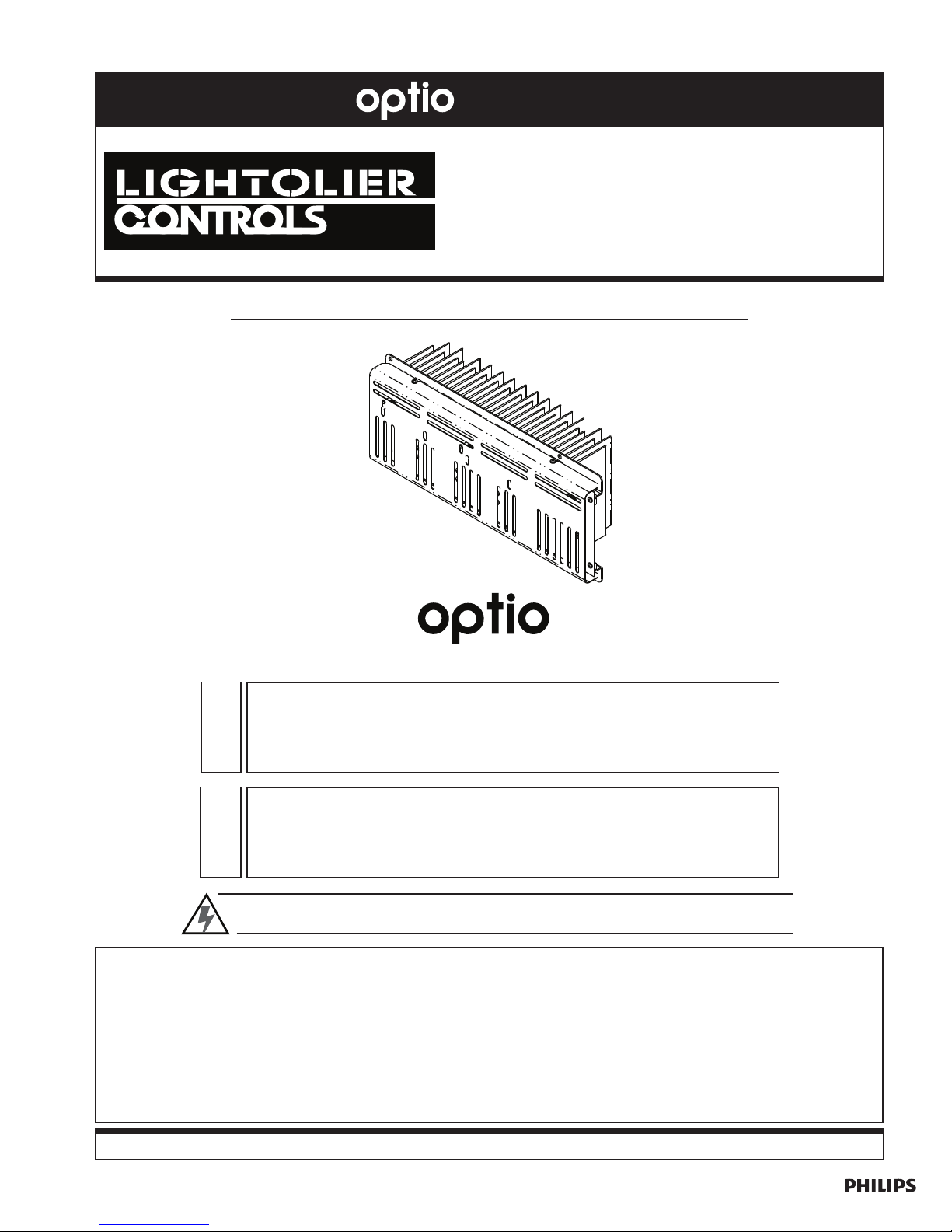
3-WIRE FLUORESCENT DI ER ODULES Installation
Instructions
The Optio 3-Wire Fluorescent Dimmer odules offer reliable dimming of 3-wire phase control
dimming ballasts where two wires are used for hot and neutral, and a third wire carries the phase
control signal. (For control of Lightolier Controls PowerSpec HDF dimming ballasts, use an Optio
"HDF" series module).
All Optio Dimmer odules have identical mounting dimensions, allowing them to be easily swapped
within any of the Optio Lighting Control Panels. (Use caution to ensure that quad dimmer modules
are not installed into module spaces wired for dual dimmer modules.)
Descri tion
WARNING: Installing the module with power applied to the cabinet may expose you to
dangerous voltage and damage the device. Remove power before installing. A qualified
electrician should perform this installation.
Any combination of Optio dimming and relay modules may be installed in the Lighting Control Panel.
Blank covers UST be installed in any unused spaces. Pull the jumper (shorting plugs) before
installing.
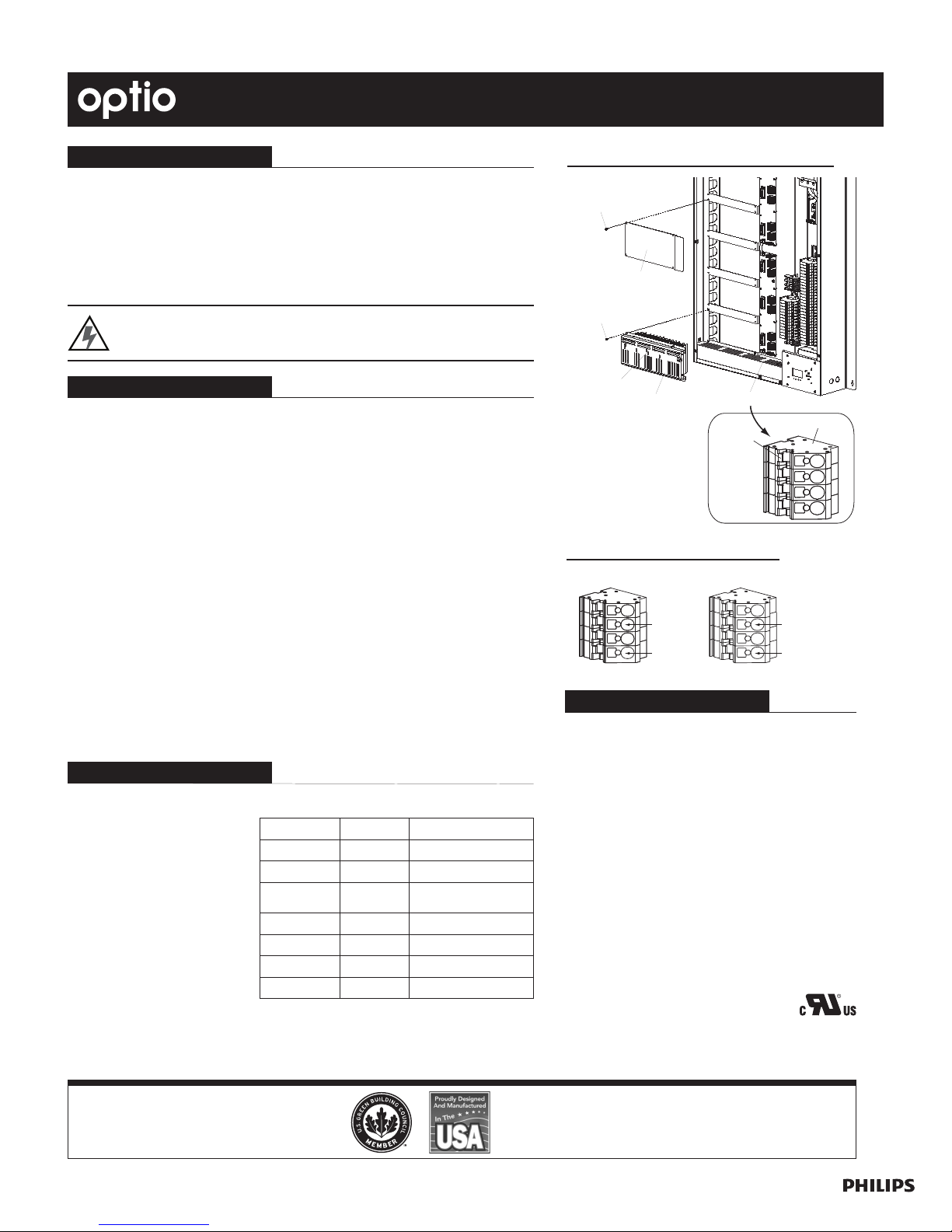
To install modules:
1. Unpack module and recycle or properly discard packaging materials. (Be sure to keep this
instruction sheet for future use.) Inspect dimming module for signs of damage during transit.
2. Disconnect main power to Optio Lighting Control Panel.
3. Open dimmer module side of panel front cover.
4. If present, remove blank cover from location where module is to be installed (Figure 1).
When possible, lower modules should be installed first.
5. Remove shorting plugs from the load terminal block. (The shorting plug is the red tab
protruding from the green load terminal block. To remove, grasp the shorting plug and
gently pull.) Note: The dimmer module will not operate properly if the shorting plug
is left in circuit.
6. Gently insert module into lighting control panel, heatsink first. Secure module using four
screws (provided). Dimmer odule should be installed with the heatsink facing away from
you. Note: The connectors of 277VAC Optio modules are keyed, pre enting the insertion
of modules into panels of the incorrect oltage. Do not force modules into slots.
7. Connect control wire from fluorescent dimming ballast to appropriate terminals on panel.
8. Close panel front cover.
Figure 1: Ins alling Modules and Blank Covers
Installation Procedure
NOTE: The Optio 9- odule
Panel is used to illustrate the
installation. However, the
module installation is identical
for all Lighting Control Panel
models.
Electrical S ecifications
O eration
Optio Dimmer odules are
equipped with a "Focus Button" on
each circuit (Figure 1). Tapping
the focus button quickly will turn the
circuit on to full, tapping it quickly
again will turn the circuit off.
Pressing and holding the focus but-
ton will ramp the dimmer up to full
intensity. If the focus button is
released before reaching full inten-
sity, the dimmer will stop at that rel-
ative output.
Red LED Green LED Condi ion
Off Off No mal
Off Flashing No Load
Off On Focus Mode
(cont olled at dimme )
Slow Flashing Off Ove load
Fast Flashing Off Ove Tempe atu e
On Off Communication E o
Flashing Flashing Miswi e to Line
Status LED Indications:
Philips Lighting Controls
2828 Trade Center Drive, Suite 130B
Carrollton, Texas 75007
Technical/Sales assistance: 1-800-526-2731
Made in U.S.A.
www.philipslightiingcontrols.com P/N 85-6358B
Figure 2: Ballas Wiring Connec ions