Philips EverFlo Q Use and care manual

Page 1 EVERFLOTM SERVICE & TECHNICAL INFORMATION 1039055, VER. 06
EverFloTM Oxygen Concentrator
EverFloTM Q OxygenConcentrator
Service & Technical Reference Manual

Page 2 EVERFLOTM SERVICE & TECHNICAL INFORMATION 1039055, VER. 06
REVISION HISTORY
Revision Description Author
06
Updated to include Field Communications
Reformatted K. Carter

Page 3 EVERFLOTM SERVICE & TECHNICAL INFORMATION 1039055, VER. 06
Chapter 1. INTRODUCTION............................................................................................................5
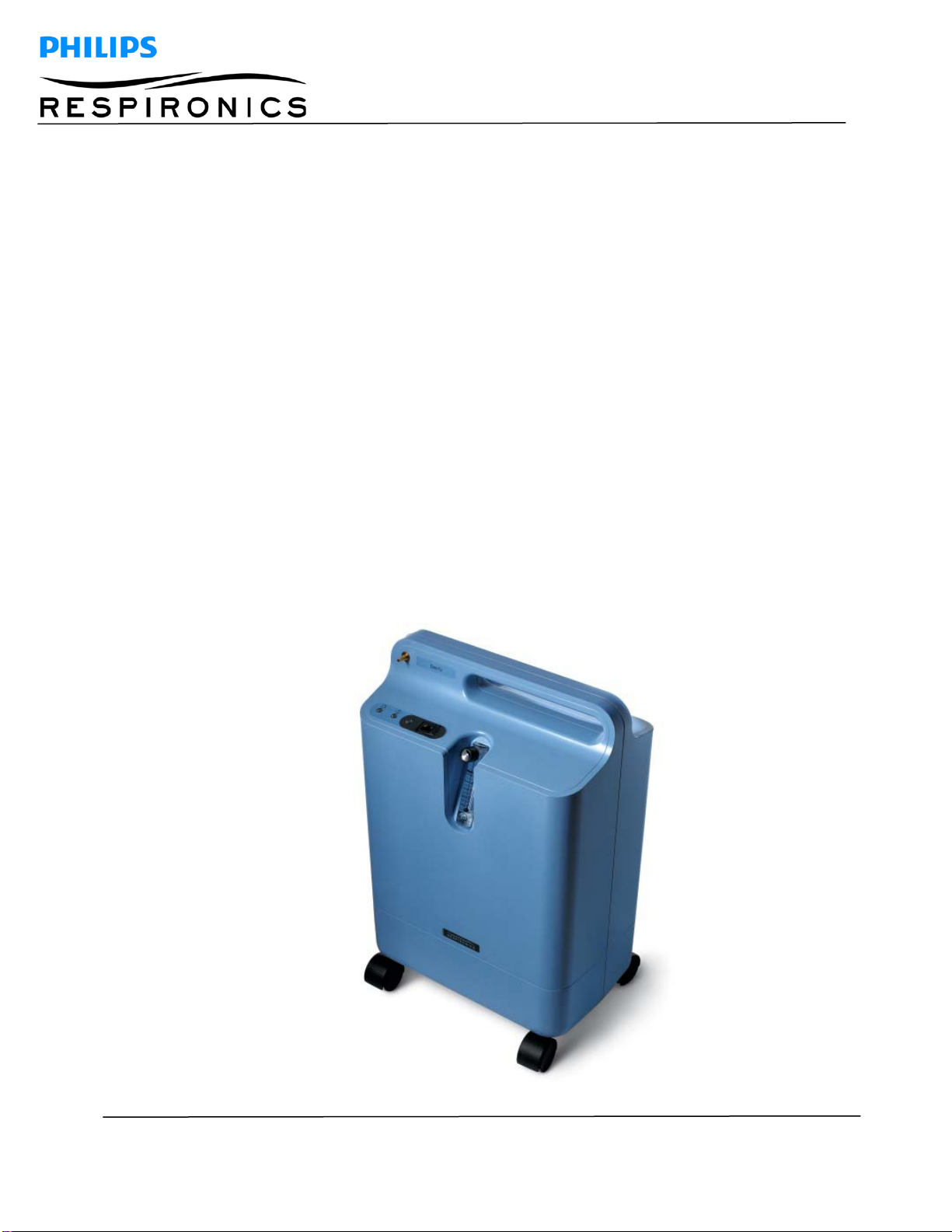
1.1 EVERFLO OXYGEN CONCENTRATOR OVERVIEW ............................................................................. 5
1.2 SERVICE NOTICE.................................................................................................................................... 5
1.3 SERVICE TRAINING................................................................................................................................. 5
1.4 SERVICE/TECHNICAL SUPPORT STATEMENT.................................................................................... 5
Chapter 2. WARNINGS & CAUTIONS...........................................................................................6
2.1 WARNINGS............................................................................................................................................... 6
2.2 CAUTIONS................................................................................................................................................ 7
Chapter 3. SPECIFICATIONS & CLASSIFICATIONS....................................................................8
3.1 SPECIFICATIONS..................................................................................................................................... 8
Chapter 4. THEORY OF OPERATION..........................................................................................10
4.1 PNEUMATIC OPERATION.....................................................................................................................10
4.2 ELECTRICAL OPERATION.................................................................................................................... 12
4.3 PCA CONTROLLER OVERVIEW...........................................................................................................12
Chapter 5. SYSTEM SETUP.........................................................................................................14
5.1 INTRODUCTION..................................................................................................................................... 14
5.2 SYSTEM SETUP PROCEDURES.......................................................................................................... 14
Chapter 6. MAINTENANCE...........................................................................................................16
6.1 DEALER ROUTINE MAINTENANCE.....................................................................................................16
6.2 EVERFLO OXYGEN CONCENTRATOR MAINTENANCE RECORD....................................................17
6.3 SYSTEM VERIFICATION PROCEDURES ............................................................................................ 18
Chapter 7. TROUBLESHOOTING & ALARMS.............................................................................31
7.1 INTRODUCTION..................................................................................................................................... 31
7.2 INDICATORS & ALARMS.......................................................................................................................31
7.3 TROUBLESHOOTING TABLE................................................................................................................32
7.4 SYSTEM PRESSURE TEST TABLE ......................................................................................................39
Chapter 8. REPAIR & REPLACEMENT.......................................................................................40
8.1 OVERVIEW .............................................................................................................................................40
8.2 REPAIR KIT REFERENCE TABLE.........................................................................................................41
8.3 FILTER COVER REPLACEMENT..........................................................................................................44
8.4 INLET FILTER REPLACEMENT ............................................................................................................ 45
8.5 REAR CABINET/POWER CORD REPLACEMENT............................................................................... 46
8.6 O2 QUICK COUPLER REPLACEMENT................................................................................................49

Page 4 EVERFLOTM SERVICE & TECHNICAL INFORMATION 1039055, VER. 06
8.7 EVERFLO AND EVERFLO Q PRESSURE REGULATOR ASSEMBLY REPLACEMENT.................... 50
8.8 EVERFLO ULTRAFILL COMPATIBLE PRESSURE REGULATOR ASSEMBLY REPLACEMENT ......52
8.9 MAIN PCA REPLACEMENT................................................................................................................... 55
8.10 SIEVE CANISTER ASSEMBLY REPLACEMENT .............................................................................59
8.11 VALVE SOLENOID REPLACEMENT .................................................................................................. 63
8.12 COOLING FAN REPLACEMENT .......................................................................................................67
8.13 CAPACITOR REPLACEMENT ........................................................................................................... 69
8.14 COMPRESSOR REPLACEMENT......................................................................................................70
8.15 MICRO-DISK FILTER & TUBING REPLACEMENT...........................................................................79
8.16 FLOW METER REPLACEMENT ........................................................................................................80
8.17 FRONT CABINET REPLACEMENT...................................................................................................81
8.18 RETURNS / PACKAGING...................................................................................................................84
8.19 LABELS................................................................................................................................................ 88
Chapter 9. TESTING .....................................................................................................................90
9.1 LONG LIFE FILTER TEST......................................................................................................................90
9.2 EVERFLO SYSTEM FINAL TEST .......................................................................................................... 90
9.3 EVERFLO TEST DATA SHEET............................................................................................................... 93
Chapter 10. TOOLS AND EQUIPMENT.......................................................................................94
10.1 ACCEPTABLE TEST EQUIPMENT ....................................................................................................95
Chapter 11. SERVICE SOFTWARE.............................................................................................96
11.1 EVERFLO SERVICE TOOL.................................................................................................................96

Page 5 EVERFLOTM SERVICE & TECHNICAL INFORMATION 1039055, VER. 06
Chapter 1. INTRODUCTION
This section provides an introduction to the EverFlo Oxygen Concentrator as well as contact
and service training information.
1.1 EVERFLO OXYGEN CONCENTRATOR OVERVIEW
The EverFlo Oxygen Concentrator produces concentrated oxygen from room air for delivery
to a patient requiring low flow oxygen therapy. The oxygen from the air is concentrated using
a molecular sieve and a pressure swing adsorption process. The EverFlo Oxygen
Concentrator is not intended to be life supporting or life sustaining.
1.2 SERVICE NOTICE
The EverFlo Oxygen Concentrator is designed so that trained Service Technicians can
perform repair and testing procedures. Only trained and qualified personnel should repair
these products using authorized parts.
1.3 SERVICE TRAINING
Philips Respironics offers service training for EverFlo Oxygen Concentrators. Training
includes complete disassembly of the device, troubleshooting subassemblies and
components, repair and replacement of components, setup of test equipment, and necessary testing. For more
information, contact the Respironics Customer Service department @ 1-800-345-6443.
1.4 SERVICE/TECHNICAL SUPPORT STATEMENT
For technical assistance, please contact Philips Respironics Service and Technical Support.
U.S.A. and Canada
Phone: 1-800-345-6443
Fax: 1-800-886-0245
International
Phone: 1-724-387-4000
Fax: 1-724-387-5012
CAUTION
U.S. federal law restricts this device to sale by or on the order of a physician.

Page 6 EVERFLOTM SERVICE & TECHNICAL INFORMATION 1039055, VER. 06
Chapter 2. WARNINGS & CAUTIONS
Warnings and cautions are used throughout this manual to identify possible safety hazards, conditions that may
result in equipment or property damage, and important information that must be considered when performing
service and testing procedures on the EverFlo Oxygen Concentrator. Please read this section carefully before
servicing the EverFlo Oxygen Concentrator. Additional Warning and Cautions can be located in the EverFlo User
Manual.
WARNING
Warnings indicate the possibility of injury to people.
CAUTION
Cautions indicate the possibility of damage to equipment.
2.1 WARNINGS WARNINGS
•
For proper operation, yourconcentrator requires unobstructed ventilation. The ventilation ports
are located at the top and bottom of the rear cabinet. Keep the device 6 to 12 (15 to 30 cm)
inches away from walls that could impede adequate airflow to the device. Always make sure
that these areas are not obstructed by items, which may impede ventilation. Do not place
concentrator in a small closedspace.
•
Servicing of this device must be referred to an authorized and trained Respironics home care
provider.
•
Oxygen generated by this concentrator is supplemental and should not be considered life
supporting or life sustaining. In certain circumstances, oxygen therapy can be hazardous; any
user should seek medical advice prior to using thisdevice.
•
Oxygen vigorously accelerates combustion and should be kept away from heat or open flame.
Not suitable for use in the presence of a flammable anesthetic mixture with air, with oxygen,
or with nitrous oxide.
•
Do not smoke or allow others to smoke or have open flames near the concentrator when it is
in use.
•
Do not use oil or grease on the concentrator or its components as these substances, when
combined with oxygen, can greatly increase the potential for a fire hazard and personal injury.
•
Do not use the concentrator if either the plug or power cord is damaged. Do not use extension
cords or electricaladaptors.
•
Do not attempt to clean the concentrator while it is plugged into an electrical outlet.

Page 7 EVERFLOTM SERVICE & TECHNICAL INFORMATION 1039055, VER. 06
WARNINGS
•
Avoid handling the molecular sieve material. Respironics recommends the return of the sieve
canister assembly to Respironics for any service that involves sieve disposal.
•
Use extreme caution when handling the compressor capacitor as it holds an electrical charge
until is it properlydischarged.
•
Device operation above or outside of the voltage, LPM, temperature, humidity and/or altitude
values specified may decrease oxygen concentrationlevels.
•
If the EverFlo Oxygen Concentrator has been subjected to sub-freezing temperatures for an
extended period, it should be allowed to warm up to the stated operating temperatures before
power up. Failure to do so could result in improper performance and or alarm conditions until
the device reaches normal operating temperatures.
2.2 CAUTIONS
CAUTIONS
U.S. federal law restricts this device to sale by or on the order of a physician.
Do not place liquids on or near thedevice.
If liquid is spilled on the device, turn the power off and unplug from electrical outlet before attempting to
clean up aspill.
When using liquid leak detector, be careful not to allow it to contact electrical parts.
Make sure connections of fittings, tubing, and hoses aresecure.
Be cautious when using thread sealants because they can cause extensive damage to the internal parts
of the device if allowed within tubing orfittings.

Page 8 EVERFLOTM SERVICE & TECHNICAL INFORMATION 1039055, VER. 06
Chapter 3. SPECIFICATIONS & CLASSIFICATIONS
3.1 SPECIFICATIONS
Model
Numbers
Voltage
Operational
Power
Frequency
Power
Consum
ption
Oxygen
Concentrati
on Zero to
Maximum
Flow LPM
Sound
Level
Weight
1020000
1020001
1020002
1020003
1039362
1039363
120 VAC +
10% 60 Hz 350 W
At 120 VAC 90 - 95.5% 45 dBA typ
31 lbs (14 kg)
1020002BR
1020003BR
1039364
1039365
120 VAC +
10% 60 Hz 350 W
At 120 VAC 90 - 95.5% 43 dBA typ
31 lbs (14 kg)
1020014
1020015
120 VAC +
10%
60 Hz
350 W
At 120 VAC
90 - 95.5%
<40 dBA
typ
31 lbs (14 kg)
1020006
1020009
1020010
1020011
1020012
1020016
1020017
1020020
1039366
1039370
230 VAC +
10% 50 Hz <300 W
At 230 VAC 90 - 95.5% 43 dBA typ
33 lbs (15 kg)
1020008
1039368
1104000
230 VAC +
10% 50 Hz <300 W
At 230 VAC 87 - 95.5% 43 dBA typ
33 lbs (15 kg)
1020007
1039367
230 VAC +
10%
50 Hz
<300 W
At 230 VAC
87 - 95.5%
<40 dBA
typ
33 lbs (15 kg)
1125558
230 VAC +
10%
50 Hz
<300 W
At 230 VAC
90 - 95.5%
<40 dBA
typ
33 lbs (15 kg)
1020004
1020005
220 VAC +
10%
60 Hz
320 W
At 220 VAC
90 - 95.5% 45 dBA typ
33 lbs (15 kg)
1020013
220 VAC +
10%
60 Hz
<300 W
At 220 VAC
90 - 95.5% 43 dBA typ
33 lbs (15 kg)
1102443
230 VAC +
10% 60 Hz
<300 W
At 230 VAC 90 - 95.5% 43 dBA typ
33 lbs (15 kg)

Page 9 EVERFLOTM SERVICE & TECHNICAL INFORMATION 1039055, VER. 06
All Models
Dimensions 22.8” (58 cm) x 15” (38 cm) x 9.5” (24 cm) (H x W x D)
Oxygen Purity
Alarms Low Oxygen at 82% purity (For OPI models only), Very Low Oxygen
at < 70%
Operating
Temperature 55o F to 90o F (13o C to 32o C)
Storage and Transport Temperature 29o F to 160o F (-34o C to 71o C)
Relative
Humidity 15 to 95%, noncondensing
Outlet Pressure 5 to 7 psi (0.34 to 0.48 Bar)
Operating
Altitude 0 to 7,500 ft (0 to 2,286 m) meets specifications
7,500 to 13,123 ft (2286 to 4000 m) not specified, exceeds specified
operating altitude
Maximum Flow at 0 & 7 kPa Outlet Pressure 5 LPM (3 LPM During trans fill operation)
Pressure Relief Valve 49 to 55 psi (338 to 378 kPa)
Each EverFlo unit is measured in the factory with an Oxygen Analyzer that measures oxygen concentration with an
accuracy specification of +/- .1 %. When
using an Oxygen Analyzer with an accuracy specification of +/- 2 % to test
the Oxygen Concentration for an EverFlo Oxygen Concentrator, you may receive
inaccurate readings below the
acceptable pass criteria for the device. This 2% offset should be taken in to consideration when determining if the
EverFlo is
functioning properly. A more accurate Oxygen Analyzer may also be used for a more precise
measurement of the oxygen purity. As an example, a unit could be
measured in the factory with the +/- 1% Oxygen
Analyzer to measure 91.1%. If this same unit is then measured with a +/- 2% Oxygen Analyzer, the reading could
display a result of 89.1%. With the +/- 2% Oxygen Analyzer, it may inaccurately look like the unit falls below the 90-
95.5% specification, when in fact the unit is within specification.
Refer to User Manual (1041063) for classification, standards compliance, and EMC requirements.

Page 10 EVERFLOTM SERVICE & TECHNICAL INFORMATION 1039055, VER. 06
Chapter 4. THEORY OF OPERATION
This section describes the theory of operation for the EverFlo Oxygen Concentrator.
4.1 PNEUMATIC OPERATION
Refer to Figure 4-1 while reading the following discussion.
The room air is drawn into the unit through the air inlet filter by the compressor. The compressed air is routed to
the sieve beds through an electronically controlled Solenoid Valve Assembly. The Solenoid Valve alternates the
airflow to a pair of sieve beds that allows Oxygen production. The Solenoid Valve Assembly also alternates the
flow through the sieve beds to allow purging of the Nitrogen molecules from the sieve beds.
At startup, the valve/solenoid is de-energized allowing compressed air to flow through both sieve beds until the
pressure sensor builds up to switching pressure. At switching pressure, a 12-volt signal is received at the
valve/solenoid closing off the input and allowing the compressed air to cycle through one of the sieve beds. As
the air is cycled through one of the sieve beds, the molecular sieve material traps the Nitrogen molecules from
the air and allows the Oxygen enriched air to flow through the sievebed.
At 5 liters of flow, approximately 1/3 of the Oxygen enriched air enters the product tank and the other 2/3 of the
Oxygen enriched air is passed through an orifice in the sieve bed to purge the trapped Nitrogen molecules from
the sieve bed, allowing the sieve material to be ready for Oxygen production during the next cycle.
The concentrated Oxygen is stored in the product tank. The product tank is continuously filled with concentrated
Oxygen and the output from the product tank is regulated at 5.5 psig nominal. The product tank pressure is
continuously monitored using a pressure sensor. The stored Oxygen is delivered to the patient through a
pressure regulator, an externally adjustable flow meter and a microbial filter.
NOTE
In the beginning, the 230V units, had an orifice built into the purge valve. The
electronically controlled purge valve controls the Oxygen flow timing from one sieve
bed to the other based on the flow meter setting.

Page 11 EVERFLOTM SERVICE & TECHNICAL INFORMATION 1039055, VER. 06
Figure 4-1: Pneumatic Block Diagram (Non-O2 Piloted)

Page 12 EVERFLOTM SERVICE & TECHNICAL INFORMATION 1039055, VER. 06
4.2 ELECTRICAL OPERATION
The EverFlo Concentrator is a medical device, which produces concentrated oxygen from room air for delivery to
a patient. It uses a molecular sieve and a pressure swing adsorption process to concentrate oxygen from air. The
device consists of filters, a compressor, a sieve canister module, a set of valves, a microprocessor-based
electronic controller PCA, a flow meter and a cooling fan – all contained within a plastic enclosure.
The EverFlo Embedded Software—via the microprocessor contained on the PCA Controller—controls the sieve
valves used to generate the oxygen, measures/monitors the pressure & oxygen levels, drives the Elapsed Time
counter (Hour meter), reports exception conditions to the User via visual and audible indicators and provides
diagnostic information to a Host computer via an RS232 communications interface.
4.3 PCA CONTROLLER OVERVIEW
All the electric / electronic functions of the EverFlo Concentrator reside on the PCA Controller. A block diagram of
the PCA controller is provided in Figure A. The reader is urged to continually refer to this diagram when reading
the remaining sections of thisdocument.
The PCA controller can be sub-divided into 2 major sections:
1.
Power distribution and DC voltagegeneration.
2.
Monitoring / Control / User Interface.
Figure 4-2: EverFlo PCA Controller Block Diagram

Page 13 EVERFLOTM SERVICE & TECHNICAL INFORMATION 1039055, VER. 06
4.3.1 POWER
The AC mains power, via the line cord, is brought onto the PCA and the “switched” AC is distributed to the
Compressor, the Cooling Fan and to the AC to DC conversion module. The DC voltages that are generated are
used to power the remainingcircuitry.
The PCA contains a 1 Farad “super capacitor” which is used to sound the Audible Indicator when the AC mains
power is absent AND the mains switch is in the ON position. The purpose is to alert the User to the fact that
there has been a loss of AC mains power (that is, an AC mains power failure, a plug removal, a blown fuse). The
circuitry functions as follows:
1.
During normal operation, the capacitor is energized (charged) using the +5 VDC. The capacitor
reaches full charge after approximately ½ hour of systemon-time.
2.
The mains switch has a 2nd set of contacts that are used to determine whether the switch is open
or closed. If the switch is closed (in the ON position) and the microprocessor is not functional (no
DC power), then the backup circuitry is such that it will turn on the Audible Indicator, using the
“super cap” as its energysource.
The “super cap” is capable of sounding the Audible Indicator for a period of greater than 8 minutes, given that it
is fully charged.
4.3.2 MICROPROCESSOR AND ASSOCIATED CIRCUITRY
The remainder of the PCA controller electronics is centered around the MSP430F155 microprocessor. The
microprocessor is the only processing element contained in the EverFlo concentrator. In addition to the
microprocessor, the “remaining circuitry” consists of sensors, LEDS, a piezo Audible Indicator, amplifiers / signal
conditioners, communication buffers and discrete components.
The embedded software, in conjunction with the microprocessor and its associated hardware, is used to control
the sieve valves, measure/monitor the pressure & oxygen levels, control the oxygen sensor, drive the Hour
meter, reports exception conditions to the User via visual and audible indicators and provide diagnostic
information to a Host computer via an RS232 communications interface.

Page 14 EVERFLOTM SERVICE & TECHNICAL INFORMATION 1039055, VER. 06
Chapter 5. SYSTEM SETUP
5.1 INTRODUCTION
This section provides information regarding setup and operation of the EverFlo Oxygen Concentrator as needed
for servicing, repairing, and testing the device.
5.2 SYSTEM SETUP PROCEDURES
1.
Select a location that allows the concentrator to draw in room air without being restricted. Make
sure that the device is at least 6 to 12 inches (15 to 30 cm) away from walls, furniture, and
especially curtains that could impede adequate airflow to the device. Do not place the device
near any heat source.
2.
Plug the EverFlo Oxygen Concentrator into an electricaloutlet.
3.
If you are NOT using a humidifier, connect the cannula to the EverFlo Oxygen Outlet Port, as
shown below. Proceed to step4.
4.
If you are using a humidifier follow thesesteps:
a.
Open the filter door on the back of thedevice.
b.
Remove the humidifier connector tube from the back of the filter door and replace the filter
door.
c.
Fill the humidifier with water following the manufacturer’sinstructions.
d.
Mount the filled humidifier on the top of the EverFlo device inside the velcrostrap.
e.
Tighten the velcro strap around the bottle and secure it so it is held firmly in place.
f.
Connect the humidifier connector tube (that you retrieved from the filter door) to the Oxygen
Outlet Port.
g.
Connect the other end of the humidifier connector tube to the top of the humidifier withthe
elbow in the tubing facing thefront.
h.
Connect your cannula to the humidifier bottle according to the humidifier bottle manufacturer’s
specifications.
NOTE
Please refer to the appropriate User Manual for additional information.

Page 15 EVERFLOTM SERVICE & TECHNICAL INFORMATION 1039055, VER. 06
5.
Press the power switch to the On [I] position. Initially, all the LEDS will illuminate and the audible
alert will sound for a few seconds. After that time, only the green LED should remain lit. You can
begin breathing from the device immediately even though it typically takes 10 minutes to reach
oxygen purity specifications. The device normally takes 10 minutes to reach oxygenpurity
specifications.
6.
Adjust the flow to the proper setting by turning the knob on the top of the flow meter until the ball is
centered on the line marking the specific flowrate.
7.
Be sure oxygen is flowing through the cannula. If it is not, refer to the Troubleshooting section of
this manual.
8.
When you are not using the oxygen concentrator, press the power switch to the Off [O] position.

Page 16 EVERFLOTM SERVICE & TECHNICAL INFORMATION 1039055, VER. 06
Chapter 6. MAINTENANCE
6.1 DEALER ROUTINE MAINTENANCE
This section describes scheduled and routine maintenance procedures. Normal routine maintenance involves
periodic checking, cleaning, and or replacing the following items as necessary:
•
Inlet Filter
•
Micro-Disk Filter
•
Cabinet cleaning
•
LPM flow setting to the prescribedlevel
•
Oxygen concentration level
Routine maintenance is very important in prolonging dependability and in reducing costly repairs. Long-term
maintenance and regular checking of the filters helps assure the efficient operation of the unit.
6.1.1 FILTERS
Respironics recommends checking and replacing the Inlet Filter every two (2) years. Respironics also
recommends checking and replacing the Micro-Disk filter as necessary.
6.1.2 CABINET
Commensurate with hospital or homecare policies, Respironics recommends cleaning the cabinet and
inspecting for damage as necessary. Ensure that the small holes on the Inlet Filter door are unobstructed. Refer
to the Tools and Equipment section for approved cleaning solution.
6.1.3 FLOW SETTING
Commensurate with hospital or homecare policies, Respironics recommends verifying the patient flow setting as
necessary.
6.1.4 OXYGEN CONCENTRATION VERIFICATION
Commensurate with hospital or homecare policies, Respironics recommends verifying the oxygen concentration
level per homecare provider's policies as necessary. Refer to the Testing section for more detailed instructions
on how to check the oxygen concentration level.
6.1.5 COMPRESSOR
Respironics does not require routine maintenance or recommend field service of the EverFlo Oxygen
Concentrator compressor. The compressor may require replacement when:
•
The system pressure is not within specifications and there are no leaksdetected.
•
The compressor bearings have worn to a point that make the compressor noticeably louder.
6.1.6 HUMIDIFIER CONNECTOR TUBE AND CONNECTOR
Commensurate with hospital or homecare policies, Respironics recommends disinfecting the tube and
connector using 70% isopropyl alcohol.

Page 17 EVERFLOTM SERVICE & TECHNICAL INFORMATION 1039055, VER. 06
6.2 EVERFLO OXYGEN CONCENTRATOR MAINTENANCE RECORD
MODEL NUMBER SERIAL NUMBER
DATE/HOURS/LPM
(Record at Each Check)
FILTERS
(Clean & Replace as Necessary)
OXYGEN
CONCENTRATION
(Check Level)
Inlet Micro-Disk
CABINET
(Clean and Inspect as Necessary)
FLOW SETTING
(Check Setting)
DATE PURCHASED

Page 18 EVERFLOTM SERVICE & TECHNICAL INFORMATION 1039055, VER. 06
6.3 SYSTEM VERIFICATION PROCEDURES
The following procedures may be performed at any time to ensure that the EverFlo Concentrator is functioning
properly.
6.3.1 SYSTEM SELF TEST AND START UP TEST
1.
Connect the power cord to the proper powersource.
2.
Turn on the unit by moving the power switch to the ON (I) position and verify the following:
•
All LEDs light up and the audible alarm sounds for twoseconds.
•
The unit starts to run.
•
The red and yellow LED lights go off and the audible alarmstops.
•
The green LED stays on.
6.3.2 POWER LOSS ALARM TEST
1.
Test the power loss alarm as follows:
a.
Connect the device to a proper powersource.
a.
Let the device warm up for two minutes to charge the capacitor.
b.
Disconnect the device from the power source and move the power switch to the On (I) position
and verify an audible alarm soundscontinuously.
c.
The alarm should have sufficient power to sound for 10 minutes. Verify that the EverFlo
Device alarms.
d.
If the audible alarm does not sound, replace the MainPCA.
6.3.3 OUTLET/REGULATED PRESSURE TEST
1.
Power up the unit and allow it to run for at least two minutes tostabilize.
2.
Set the flow meter to 5 LPM (1 LPM for units equipped with pediatric flowmeters).
NOTE
If using the Concentrator tool kit (H647), be sure to remove the DISS outlet fitting
from the tubing before proceeding to step 3.

Page 19 EVERFLOTM SERVICE & TECHNICAL INFORMATION 1039055, VER. 06
3.
Connect the pressure gauge from the tool kit to the outlet barb. The flow ball should drop to 0.0
LPM.
4.
If the outlet pressure does not fall between 5.0 and 7.0 psig, perform steps 5 through 14. If the
pressure does fall between 5.0 and 7.0 psig, remove pressure gauge, the test is now complete.
5.
Turn the unitoff.
6.
Remove the pressure gauge from the outletbarb.
7.
Remove the front and rearcabinets.
NOTE
Be sure to hold the pressure gauge in a vertical position.

Page 20 EVERFLOTM SERVICE & TECHNICAL INFORMATION 1039055, VER. 06
8.
Insert a “T” from the tool kit in between the regulator and the clear oxygen tubing and connect the
pressure gauge.
9.
Turn the device on and set the flow meter to 5 LPM (1 LPM for units equipped with pediatric
flow meters).
10.
With the gauge held in a vertical position, verify that the regulated pressure is at 5.5 ± 0.25 psig.
11.
If the regulated pressure needs adjusted, place a 3/32” Allen wrench in the adjusting screw on the
end of theregulator.
12.
Disconnect the pressure gauge and “T”fitting.
13.
Reconnect the clear oxygen tubing to the pressure regulator.
14.
Install the front and rearcabinets.
NOTE
If the regulated pressure is low, turn the wrench clockwise to increase the regulated pressure. If the
regulated pressure is high, turn the wrench counter-clockwise.
Other manuals for EverFlo Q
1
This manual suits for next models
1
Table of contents
Other Philips Oxygen Equipment manuals