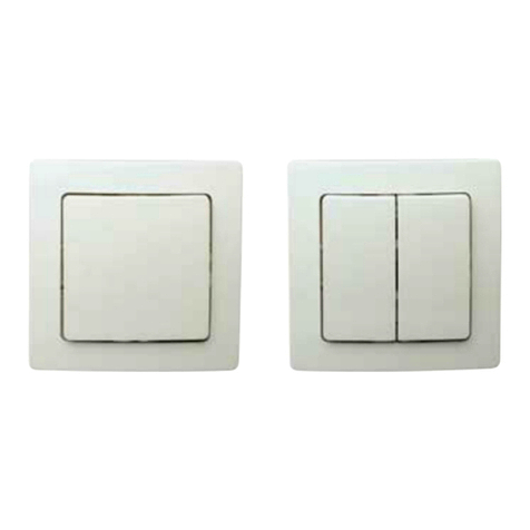
SCENE 1
SCENE 2
ON
OFF
ommissioning
Scene control and scene setting
Decommissioning the switch
Battery replacement and service
Battery LED Indication
se the Philips Field App to add a switch to an EasySense group. An App ser Manual
can be found at www.philips.com/easysense. Follow the ow of either “Create group” or
“Add to group” until the “Adding wireless switch” screen shows up. Simultaneously press
the “On” and “O” buttons for at least 4 seconds to move the switch into commissioning
mode.
pon entering commissioning mode the LED indicator ashes at a 500msec duty cycle
for 30 seconds (500 msec on/500 msec o). The luminaire with Easysense will blink
twice when the zigbee channel is matched. Finish the work ow on the App for creating
or adding to the group.
A 30 second time-out is used during commissioning mode. If no reaction is received from
the EasySense for 30 seconds, the device will move back to the decommissioned state.
When the device is commissioned, it can only enter commissioning mode again after
being properly decommissioned.
When the device is commissioned, all commission data is stored in the switch memory.
This memory is held even in the event of a battery changeout.
Decommissioning is achieved pressing the decommission
button and holding for at least 1 second. See diagram below
for location of the button, which can be accessed with a
paper clip. After decommissioning, the switch is out of the
network and can be re-added to a group by following the
commissioning procedure.
To replace the battery, disassemble the switch from the wall to access the Switch
Assembly. Locate the “Button Cover Access Slot” at the bottom of the Button Cover
Assembly (see drawing). Gently pry with a screwdriver to separate the cover. The battery
will be visible pressed against the switch circuit board by the battery clip. Carefully
remove the old battery. Replace only with lithium button cell battery CR2032. Be sure
the battery “+” is facing the battery clip. Snap the cover back onto the Button Cover
Assembly with the battery at the lower end of the switch. Re-assemble the switch
to the wall.
Other than battery replacement, this switch is non-serviceable. A damaged or
non-functioning switch should be completely replaced and should not be repaired.
Decommission button
Button over Access Slot
(also location of battery insulator strip on new switch)
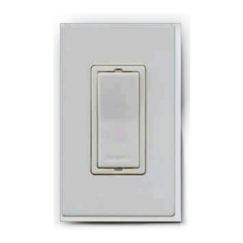
Pressing a Scene button on the switch will instruct the sensors and lighting in the group
to go to their programmed setting. Scenes can be custom congured through the Philips
Field Apps. See the EasySense App ser Manual on www.Philips.com/easysense. The
default settings are: Scene 1-- 60% light output; Scene 2 – 20% light output.
Button state Battery level – Normal ( > 2.5V)
Battery level – Low
( 2.3 < Low < 2.5V)
Battery level – Dead
( < 2.3V)
Any button in
pressed state
RED LED blink
6 cycles, 50ms On –
100ms O
RED LED ash once
50ms On
RED LED O
All buttons in
released state
RED LED O RED LED O RED LED O

