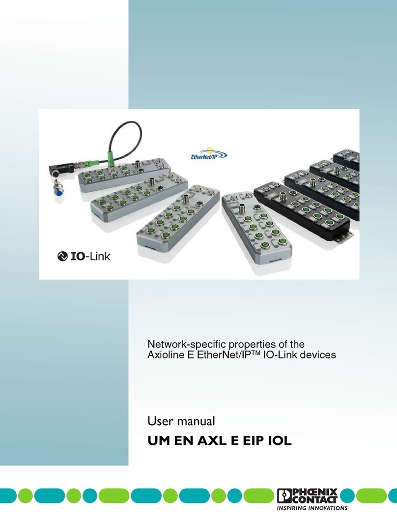
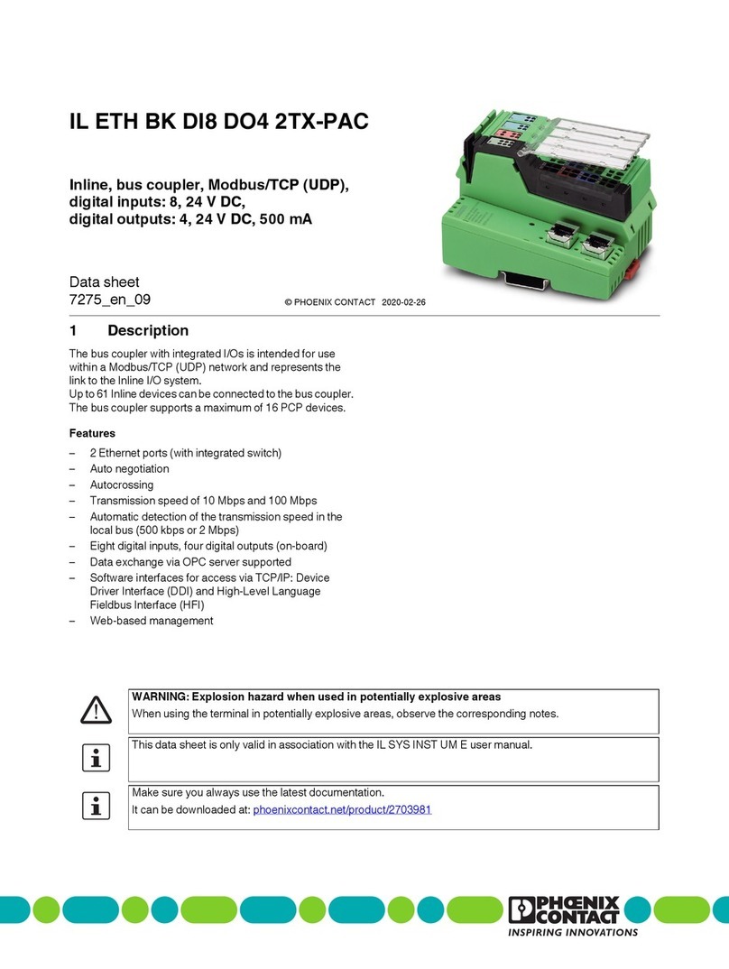
Phoenix Contact FL MGUARD 1000 Series User manual

User manual
UM EN MGUARD NT
FL MGUARD 1000
Web-based management
mGuardNT 1.3.x

2020-07-09
PHOENIX CONTACT GmbH & Co. KG • Flachsmarktstraße 8 • 32825 Blomberg • Germany
phoenixcontact.com
108420_en_03
FL MGUARD 1000 – Web-based management – mGuardNT 1.3.x
Designation Version Order No.
FL MGUARD 1102 1153079
FL MGUARD 1105 1153078
For further information see mGuardNT 1.3.x firmware Release Notes.
User manual
This user manual is valid for:
UM EN MGUARD NT, Revision 03

Table of contents
108420_en_03 PHOENIX CONTACT 3 / 72
Table of contents
1 For your safety ...........................................................................................................................5
1.1 Identification of warning notes ............................................................................... 5
1.2 Qualification of users ............................................................................................. 5
1.3 Intended use.......................................................................................................... 5
1.4 Modifications to the product .................................................................................. 5
1.5 IT security.............................................................................................................. 5
1.6 About this user manual .......................................................................................... 7
1.7 Support.................................................................................................................. 7
2 mGuardNT basics ......................................................................................................................9
2.1 Device properties and scope of functions.............................................................. 9
2.2 Network ............................................................................................................... 11
2.3 Firewall ................................................................................................................ 11
2.3.1 Easy Protect Mode ............................................................................... 12
3 Using the web-based management .........................................................................................13
3.1 Establishing a network connection to the device ................................................. 13
3.2 User login ............................................................................................................ 13
3.3 User logout .......................................................................................................... 14
3.4 Help regarding the configuration.......................................................................... 15
3.4.1 Page structure and function ................................................................. 15
3.4.2 Icons and buttons ................................................................................. 16
3.4.3 Entering and changing values .............................................................. 17
3.4.4 Error messages .................................................................................... 17
3.4.5 Working with tables .............................................................................. 18
3.4.6 Resetting the device configuration to factory settings .......................... 19
3.4.7 Creating a snapshot ............................................................................. 19
3.4.8 Input: netmask and network ................................................................. 21
3.4.9 CIDR (Classless Inter-Domain Routing) ............................................... 22
4 Menu: Password ......................................................................................................................23
5 Menu: Device access ...............................................................................................................25
6 Menu: Network .........................................................................................................................27
6.1 Network >> Interfaces ......................................................................................... 27
6.1.1 Interfaces ............................................................................................. 27
6.1.2 Routes ................................................................................................. 34
6.1.3 NAT ..................................................................................................... 35

Product designation
4 / 72 PHOENIX CONTACT 108420_en_03
6.2 Network >> DHCP server .................................................................................... 42
6.3 Network >> DNS ................................................................................................. 45
7 Menu: Network security ...........................................................................................................47
7.1 Network security >> Firewall................................................................................ 47
7.1.1 Network security >> Firewall >> Firewall .............................................. 47
7.1.2 Network security >> Firewall >> Test mode alarms ............................. 53
7.2 Network security >> Firewall Assistant ................................................................ 55
8 Menu: Time and date ...............................................................................................................57
9 Menu: Firmware update ...........................................................................................................61
10 Menu: Support .........................................................................................................................63
10.1 Support >> Ping................................................................................................... 63
10.2 Support >> TCP Dump ........................................................................................ 64
11 Menu: Logs ..............................................................................................................................67
12 Appendix ..................................................................................................................................69
12.1 Using the RESTful Configuration API .................................................................. 69
12.2 Using smart mode ............................................................................................... 69

For your safety
108420_en_03 PHOENIX CONTACT 5 / 72
1 For your safety
Read this user manual carefully and keep it for future reference.
1.1 Identification of warning notes
1.2 Qualification of users
The use of products described in this user manual is oriented exclusively to:
– Electrically skilled persons or persons instructed by them. The users must be familiar
with the relevant safety concepts of automation technology as well as applicable stan-
dards and other regulations.
– Qualified application programmers and software engineers. The users must be familiar
with the relevant safety concepts of automation technology as well as applicable stan-
dards and other regulations.
1.3 Intended use
– The devices are security routers for industrial use, with integrated stateful packet in-
spection firewall. They are suitable for distributed protection of production cells or indi-
vidual machines against manipulation.
– The devices are designed for use in industrial environments.
– The devices are intended for installation in a control cabinet.
1.4 Modifications to the product
Modifications to hardware and firmware of the device are not permitted.
– Incorrect operation or modifications to the device can endanger your safety or damage
the device. Do not repair the device yourself. If the device is defective, please contact
Phoenix Contact.
1.5 IT security
For Phoenix Contact devices that can be integrated in an industrial network via Ethernet, or-
ganizational and technical measures must be taken in order to protect components, net-
works, and systems against unauthorized access and to ensure data integrity.
Phoenix Contact recommends that the following measures should be considered at the
very least.
This symbol together with the NOTE signal word warns the reader of actions
that might cause property damage or a malfunction.
Here you will find additional information or detailed sources of information.

mGuardNT firmware 1.3.x
6 / 72 PHOENIX CONTACT 108420_en_03
Perform threat analyses on a regular basis.
• In order to determine whether the measures you have taken still provide adequate pro-
tection for your components, networks, and systems, a regular threat analysis is man-
datory.
When planning systems, consider defense-in-depth strategies.
• Defense-in-depth strategies encompass several coordinated measures that include
operators, integrators, and manufacturers.
Make sure that your software/firmware is always up to date.
• Stay informed about updates for the products used. If possible, run provided updates
immediately to ensure maximum security for your product.
Deactivate unused communication channels.
• Check whether unused communication channels on the components you are using are
open (e.g., SSH, SNMP, FTP, BootP, DHCP, etc.). If possible, deactivate these chan-
nels.
Restrict access rights to the device.
• Restrict access rights for components, networks, and systems to those individuals for
whom authorization is strictly necessary.
Use strong passwords.
• Change default passwords during initial startup.
• If possible, use randomly generated passwords (password manager).
• Use strong passwords, e.g., at least ten characters long containing a mix of upper and
lower case letters, numbers, and special characters.
Use a firewall.
• Set up a firewall in order to protect your networks and the components and systems in-
tegrated in them against unauthorized network access.
• Use a firewall to segment a network or to isolate certain components (e.g., controllers).
Do not make components and systems available in public networks.
• Avoid integrating your components and systems into public networks.
• If you have to access your components and systems via a public network, use a VPN
(Virtual Private Network).

For your safety
108420_en_03 PHOENIX CONTACT 7 / 72
1.6 About this user manual
The following elements are used in this user manual:
1.7 Support
In the event of problems with your device or with operating your device, please contact your
supplier.
To get help quickly in the event of an error, make a snapshot of the device configuration im-
mediately when a device error occurs, if possible. You can then provide the snapshot to the
support team.
Bold Designations of operating elements, variable names or other accentuations
Italic – Product, module or component designations (e.g., tftpd64.exe, Config
API)
– Foreign designations or proper names
– Other accentuations
– Unnumbered list
1. Numbered list
•Operating instructions
⇒Result of an operation
For additional information on the device as well as release notes, user assistance and
software updates, visit: phoenixcontact.net/products.

mGuardNT basics
108420_en_03 PHOENIX CONTACT 9 / 72
2 mGuardNT basics
2.1 Device properties and scope of functions
Table 2-1 Device properties and scope of functions
Device properties FL MGUARD
1102 1105
HARDWARE
2 net zones (network interfaces) x x
Ethernet via RJ45 connections (transmission
speed: 10/100/1000 Mbps)
2 5
4-port Unmanaged Switch (RJ45) (bridge mode) - x
Service inputs and outputs (IOs) x x
NETWORK
Stealth mode x x
Router mode x x
Packet forwarding (router mode)
Security router x x
IP masquerading (NAT) x x
Port forwarding x x
1:1 NAT x x
Additional static routes x x
Network services (client/server)
DHCP x x
DNS x x
NTP x x
HTTPS (WBM/Config API) x x
FIREWALL
Stateful packet inspection firewall x x
Firewall (for continuous data traffic) x x
Device access (for incoming data traffic) x x
Integrity check of data packets to increase network security x x
Easy Protect Mode
Automatic protection of connected network clients without
configuration effort directly after connection of the device.
x x
Firewall Assistant
Analysis of data traffic for the automatic creation of firewall
rules.
x x

mGuardNT firmware 1.3.x
10 / 72 PHOENIX CONTACT 108420_en_03
Firewall test mode
Analysis of data traffic for the automatic extension of exist-
ing firewall rules.
x x
MANAGEMENT
Administration via web-based management (WBM) x x
Administration via RESTful Configuration API (Config API) x x
Firmware update via WBM and Config API x x
Smart mode
The access to certain management functions is imple-
mented via the Mode button on the device and without ac-
cess to a management interface.
x x
Support tools
TCP Dump (packet data analysis) x x
Ping (network analysis) x x
Log viewer (evaluation of log entries) x x
Support snapshot (status and error analysis) x x
Table 2-1 Device properties and scope of functions
Device properties FL MGUARD
1102 1105

mGuardNT basics
108420_en_03 PHOENIX CONTACT 11 / 72
2.2 Network
As a router or gateway, the device uses its network interfaces to connect subnets or net
zones. For each net zone, an own IP address is configured via which the device is reachable
in the network (see Section 6.1, “Network >> Interfaces”).
2.3 Firewall
Strictly speaking, the firewall of the device is a packet filter through which data packets
routed through the device are analyzed and then forwarded or blocked according to the
configured firewall rules (see Section 7, “Menu: Network security”).
Stateful packet inspection firewall
The mGuardNT packet filter functions as a stateful packet inspection firewall. This means
that response packets automatically pass through the firewall if they can be clearly assigned
to a related request that was already accepted. For this reason, firewall rules are never ap-
plied to response packets.
Firewall functions
The firewall can be used and configured in different ways.
Table 2-2 Options for using the mGuard firewall
No configuration required
Easy Protect Mode
(see Section 2.3.1)
Network clients are protected against external access directly after connection
of the device without the need to create firewall rules.
Configuration via web-based management (WBM) or Config API required
Firewall (packet filter)
(see Section 7.1)
Firewall rules are created and extended manually.
The rules are entered and configured in the Firewall table of the device.
Firewall Assistant
(see Section 7.2)
The Firewall Assistant analyzes and acquires the data traffic routed through the
device for any period of time (net zone 1 net zone 2).
The acquired packet data is used to deduce firewall rules that are
automatically entered in the Firewall table when the Firewall Assistant has
been stopped.
Firewall test mode
(see Section 7.1, Firewall test mode)
Data traffic unintentionally rejected by the firewall can be easily identified and
permitted through the automated creation of corresponding firewall rules.
An alarm informs the user about the event (data traffic not acquired through an
existing firewall rule).

mGuardNT firmware 1.3.x
12 / 72 PHOENIX CONTACT 108420_en_03
2.3.1 Easy Protect Mode
If the device is started in Easy Protect Mode, it automatically protects all devices con-
nected to net zone 2 (XF2–XF5) against external access (e.g., individual machines or pro-
duction cells that are connected via a switch).
For additional information refer to the “FL MGUARD 1000 – Installation and startup” user
manual, available at phoenixcontact.net/product/1153078.
Figure 2-1 Activated Easy Protect Mode (via cable bridge)
The Easy Protect Mode is activated via a cable bridge (see Figure 2-1).
The device is integrated into the existing network via its net zones 1 and 2 or XF1 and (XF2–
XF5). The existing network configuration of the connected devices does not have to be
changed.
Device configuration is not required and not possible due to the missing access option via
the web-based management (HTTPS).

Using the web-based management
108420_en_03 PHOENIX CONTACT 13 / 72
3 Using the web-based management
3.1 Establishing a network connection to the device
Establish a connection between the configuration computer and a network interface of the
device.
Default setting (network interface: XF2)
– IP address: 192.168.1.1
– Subnet mask: 24 (255.255.255.0)
For additional information refer to the “FL MGUARD 1000 – Installation and startup” user
manual, available at phoenixcontact.net/product/1153078.
3.2 User login
Enter, for example, the following web address in a web browser to start the WBM:
https://192.168.1.1 (default setting: XF2)
⇒The login page opens.
The following users can log in to the device (default setting):
– User name: admin
– Password: private
For additional information, refer to the “FL MGUARD 1000 – Installation and startup” user
manual, available at phoenixcontact.net/product/1153078.
After logging in successfully, the following start page appears.
Figure 3-1 Web-based management: login page and start page
A competing login of the admin user from several instances is not recommended and
might result in loss of data.
Immediately upon initial startup of the device, change the default password (see “Menu:
Password” on page 23).

mGuardNT firmware 1.3.x
14 / 72 PHOENIX CONTACT 108420_en_03
3.3 User logout
Figure 3-2 User logout
To log out the current user from the device, proceed as follows:
•Click on the icon.
⇒The user is logged out.
⇒All information regarding the current session is deleted.
⇒The user is forwarded to the login page.
Automatic logout
The user is automatically logged out if the following applies:
– The session has elapsed (session timeout).
– The device is restarted.
Session timeout
A logged-in user is automatically logged out once the session has elapsed (session time-
out). The user is then forwarded to the login page if he/she tries to save a configuration
change or an action.
Once the user has logged in, the timeout starts at 30 minutes. It is reset to 30 minutes if a
configuration change is saved or an action carried out.

Using the web-based management
108420_en_03 PHOENIX CONTACT 15 / 72
3.4 Help regarding the configuration
3.4.1 Page structure and function
Figure 3-3 Web-based management: menu structure and page elements
Menu structure ①
Via the main and submenu structure, the individual configuration pages can be opened.
Configuration pages are often divided into several subpages that can be called via tabs.
Tabs ②
Tabs can be selected via the tab bar at the upper edge of the screen.
Configuration page ③
In the main window of a configuration page, the parameters of the individual variables can
be changed.
The configuration page might be subdivided into several sections.
Variables ④
Variable values can be selected via a drop-down menu or a checkbox, or entered manually.
Depending on the variable, letters, numbers and/or certain special characters can be used
(see Section 3.4.3). Some variables are entered into tables (e.g., 1:1 NAT rules).
1
2
3
4
6
5

mGuardNT firmware 1.3.x
16 / 72 PHOENIX CONTACT 108420_en_03
System time ⑤
The current system time is displayed (format: Coordinated Universal Time/UTC).
Session timeout ⑥
A logged-in user is automatically logged out once the session has elapsed (session timeout)
(see Section 3.3).
3.4.2 Icons and buttons
The following examples show icons and buttons available in the WBM.
Click on the Add row button to add a new table row below the last
existing row.
Click on the Update button to select and immediately use an update
file.
Click on the Save icon to apply all changes you made on a configu-
ration page or in different menu items.
Checkbox: Check the box to enable a function.
Slide the switch to the On position to activate a function.
Slide the switch to the Off position to deactivate a function.
Click on the Waste bin icon to delete the selected table row.
Click on the Plus icon to transfer the selected table row (test mode
alarms) as a new firewall rule to the Firewall table.

Using the web-based management
108420_en_03 PHOENIX CONTACT 17 / 72
3.4.3 Entering and changing values
Changing values
To change the value of a variable, you have to apply the change with a click on the but-
ton.
It is possible to first change several values and then apply them all with a click on the
button.
Entry of impermissible values
Impermissible values of a variable cannot be applied. Usually, a corresponding error mes-
sage is already displayed when an impermissible value is entered.
If impermissible entries are present, this is also indicated by a red dot in the menu bar
(see Figure 3-3).
Correct the entries and apply the changed values with a click on the button.
3.4.4 Error messages
If an error cannot be detected during entering but only when the user tries to save the
change, the adoption of all changed values is canceled.
The icon at the upper right edge of the screen indicates that one or several configuration
errors are present. Click on the icon to have the corresponding error messages dis-
played in the right-hand page column (see Figure 3-3).
Correct the entries and apply the changed values with a click on the button.

mGuardNT firmware 1.3.x
18 / 72 PHOENIX CONTACT 108420_en_03
3.4.5 Working with tables
Some mGuardNT settings are saved as a data record. In this case, the parameters and their
values are entered in the table rows in the WBM.
Inserting table rows
•Click on the button.
⇒A new row is inserted below the last existing row.
•Click on the icon to apply the change.
⇒A new data record was created in a new table row.
Moving table rows
•Move the mouse pointer to the left of the table row you wish to move until the pointer
changes into a hand symbol.
•Click on the row and hold the mouse button down to drag and drop the row to the de-
sired position.
•Release the mouse button.
⇒The row was moved to a new position.
•Click on the icon to apply the change.
IMPORTANT: Observe the sequence of the table rows
The sequence of the table rows is decisive for the configuration of firewall rules:
The firewall rules in the table are always queried one after the other starting from the top
of the list of entries until an appropriate rule is found. Subsequent rules are then ignored.

Using the web-based management
108420_en_03 PHOENIX CONTACT 19 / 72
Deleting table rows
•In the row you wish to delete, click on the icon.
⇒The row is deleted.
•Click on the icon to apply the change.
⇒The table row and the data record were deleted.
3.4.6 Resetting the device configuration to factory settings
The current configuration is deleted and reset to factory settings. The current administrator
password, certificates and log entries are kept.
3.4.7 Creating a snapshot
A snapshot can be used for error diagnostics and communication with the support team.
The snapshot is created and downloaded as a compressed file (in tar.gz format). The snap-
shot contains the current configuration and other system information of the device (see
Table 3-1).
To safely and irrevocably delete the configuration, you have to use the smart mode func-
tion “Reset to factory settings” (see Section 12.2).

mGuardNT firmware 1.3.x
20 / 72 PHOENIX CONTACT 108420_en_03
The time the snapshot was created is indicated in the file name as follows:
<YYYY-MM-DD_hh:mm:ss> (example: snapshot_2019-10-09_22_00_00.tar.gz)
Table 3-1 Content of a snapshot
File name Content/description
config Shows the current device configuration.
bootloader_version Shows the version of the currently installed bootloader.
conntrack Shows the current content of the status table (connection tracking
table).
eds Shows current dynamic status information about certain functions
of the device.
ip_addr Shows the current network configuration of the device.
ip_neight Shows current connection information on connected (neighbored)
devices.
ip_link Shows the current connection status of the network interfaces.
ip_route Shows the current routing table.
ls_mnt_hfs Shows the files and directories currently stored in the device's file
system (/mnt/hfs).
journal Shows the current log file of the system.
nft_ruleset Shows the currently configured firewall rules.
nft_tables Shows the currently configured firewall tables.
proclist Shows the currently running processes.
serdata Shows the serialization data that was linked to the device during
creation.
services Shows the currently started services (systemd) on the system.
uptime Shows the current operating time and the load average of the sys-
tem.
userid Shows the user ID and group membership of the logged-in user.
version Shows the currently installed firmware version.
Safety-relevant information such as passwords or cryptographic keys are not contained
in the snapshot.
Other manuals for FL MGUARD 1000 Series
1
Table of contents
Other Phoenix Contact Network Hardware manuals
Popular Network Hardware manuals by other brands

VIP
VIP NVR16PRO3NP Quick installation guide

Keysight
Keysight N5227BU-660 Installation note

ADC
ADC Digivance NXD Installation and maintenance manual

ADC
ADC Cross-Connect Family FlexDSX Specification sheet

Cisco
Cisco Aironet 1000 Series Hardware installation guide

CommScope
CommScope MRJ21 Quick Fit Cassette instruction sheet

Digital Watchdog
Digital Watchdog DW-BJS1U3T-LX quick start guide

Mitsubishi Electric
Mitsubishi Electric MAC-558IF-E installation guide

D-Link
D-Link DLB-1200 Quick installation guide

Lanner
Lanner NCA-4035 user manual

Rose electronics
Rose electronics ClassView features and benefits

HP
HP StorageWorks X9720 Administrator's guide