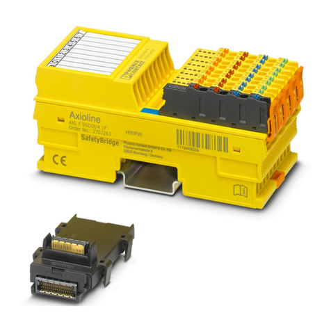
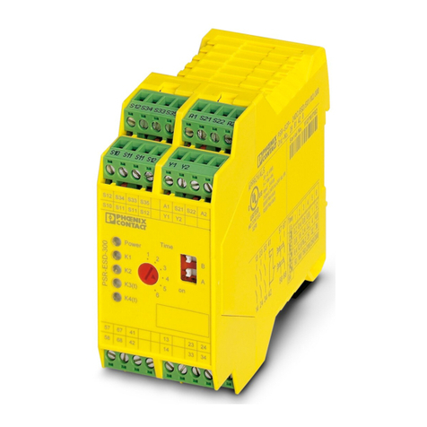
Phoenix Contact PSRmodular User manual

User manual
PSRmodular:
Configurable safety system

2020-11-05
PHOENIX CONTACT GmbH & Co. KG • Flachsmarktstraße 8 • 32825 Blomberg • Germany
phoenixcontact.com
109241_en_03
PSRmodular: Configurable safety system
The following designations are used in this user manual:
Safety modules:
Designation for the PSR-M-B1 and PSR-M-B2 base modules
Safe extension modules:
Designation for the PSR-M-EF1 ... EF8 modules, the PSR-M-EM1 ... EM7 motion monitoring modules, and the PSR-M-
TBUS1 ... TBUS2 TBUS extension modules
Standard extension modules:
Designation for the PSR-M-E1 ... E2 standard extension modules
Gateway modules:
Designation for the PSR-M-GW-PB, ...PN, ...DNET, ...CAN, ...ETH, ...ModTCP, ...CCLINK, ...ECAT modules
Explanation of the main abbreviations in the product designations
Designation Revision
as of HW/FW
Order No.
PSR-M-B1 PSR-M-B1-SDI8-SDO2-DO2-SC 00/4.0 1104981
PSR-M-B1-SDI8-SDO2-DO2-PI 00/4.0 1104972
PSR-M-B2 PSR-M-B2-SDI8-SDO4-DO4-SC 00/5.0 1104974
PSR-M-B2-SDI8-SDO4-DO4-PI 00/5.0 1104975
Safe extension modules
Standard extension modules
Gateway modules
Type Meaning Meaning
B Base module SDI Safe digital input 2A 2 A
EF Extension failsafe SDO Safe digital output
E Extension non-safe SAI Safe analog input Connection method
EM Extension motion monitoring DO Digital (signal) output SC Screw
GW Gateway PROX Proximity switch PI Push-in
MC External memory MAT Safety mat/safety edge System
TBUS TBUS extension SDOR Safe relay output M Modular
User manual
This user manual is valid for:
UM EN PSRmodular System, Revision 03

109241_en_03 PHOENIX CONTACT 3 / 232
Table of contents
1 For your safety ...........................................................................................................................7
1.1 Identification of warning notes ............................................................................... 7
1.2 Qualification of users ............................................................................................. 7
1.3 Field of application of the product.......................................................................... 8
1.3.1 Intended use .......................................................................................... 8
1.3.2 Product changes .................................................................................. 12
1.4 Safety notes ........................................................................................................ 12
1.4.1 General safety notes ............................................................................ 12
1.4.2 Electrical safety ................................................................................... 13
1.4.3 Safety of machines or systems ............................................................ 14
1.4.4 Safety when starting applications ......................................................... 15
1.5 Directives and standards..................................................................................... 15
1.6 Documentation .................................................................................................... 16
2 System description ..................................................................................................................17
2.1 PSRmodular safety system: Structure and method of operation ......................... 17
2.2 Installation ........................................................................................................... 20
2.2.1 Safety notes ......................................................................................... 20
2.2.2 Mounting location ................................................................................. 20
2.2.3 Connection technology ........................................................................ 21
2.2.4 Mechanical attachment ........................................................................ 21
2.2.5 Electrical requirements ........................................................................ 22
2.3 Using the system ................................................................................................. 23
2.4 Safe state ............................................................................................................ 24
2.5 System restart behavior....................................................................................... 25
2.6 Error detection..................................................................................................... 26
2.7 Error state............................................................................................................ 26
2.8 Diagnostic tools ................................................................................................... 26
2.9 Password protection............................................................................................ 27
3 Signal description ....................................................................................................................29
3.1 Motion signals ..................................................................................................... 33
3.2 Analog signals ..................................................................................................... 35
4 PSRmodular Software: Basics .................................................................................................37
4.1 Installing the PSRmodular Software .................................................................... 37
4.2 Basic knowledge ................................................................................................. 38
4.2.1 The tool bar .......................................................................................... 39
4.2.2 Creating a new project ......................................................................... 40
4.2.3 Changing the hardware configuration .................................................. 41
4.2.4 Changing project information ............................................................... 42

PSRmodular system
4 / 232 PHOENIX CONTACT 109241_en_03
4.2.5 Function windows: Items – Operator – Configuration ........................... 43
4.2.6 Creating the safety logic ....................................................................... 44
4.2.7 Calling functions in the context menu ................................................... 45
4.2.8 Project example ................................................................................... 46
4.2.9 Saving the project ................................................................................ 46
4.2.10 Validating the project ........................................................................... 46
4.2.11 Resource allocation ............................................................................. 47
4.2.12 Project report ....................................................................................... 48
4.2.13 Connecting to the base module ........................................................... 50
4.2.14 Password protection ............................................................................ 51
4.2.15 Establishing a USB connection ............................................................ 52
4.2.16 Monitor (status of I/Os) ......................................................................... 55
4.2.17 Monitor graphic .................................................................................... 56
4.2.18 System test .......................................................................................... 57
5 Items and operators of the PSRmodular Software ...................................................................59
5.1 Item function blocks............................................................................................. 59
5.1.1 Output item .......................................................................................... 59
5.1.2 INPUT item .......................................................................................... 71
5.2 Speed control .................................................................................................... 100
5.2.1 General information on the “Error Out” parameter .............................. 100
5.2.2 Function blocks .................................................................................. 101
5.3 Analog function block ........................................................................................ 121
5.3.1 ANALOG INPUT function block ......................................................... 121
5.4 Operator function blocks.................................................................................... 133
5.4.1 Logical operators ............................................................................... 133
5.4.2 MEMORY operators .......................................................................... 143
5.4.3 GUARD-LOCKING operator .............................................................. 151
5.4.4 COUNTER operators ......................................................................... 163
5.4.5 TIMER operators ................................................................................ 166
5.4.6 MUTING operators ............................................................................ 177
5.5 Analog operators ............................................................................................... 189
5.5.1 ANALOG COMPARATOR ................................................................. 189
5.5.2 ADDER .............................................................................................. 189
5.5.3 Equality Check ................................................................................... 190
5.6 Miscellaneous ................................................................................................... 192
5.6.1 Other operators .................................................................................. 192
5.6.2 Simulator features .............................................................................. 203
6 Installation and startup ...........................................................................................................211
6.1 Example for installation and startup................................................................... 211

Table of contents
109241_en_03 PHOENIX CONTACT 5 / 232
7 Diagnostics ............................................................................................................................213
7.1 Device diagnostics ............................................................................................ 213
7.2 System diagnostics ........................................................................................... 213
7.2.1 PSRmodular error codes ................................................................... 213
7.2.2 Error history ....................................................................................... 215
8 Maintenance, repair, decommissioning, and disposal ...........................................................217
8.1 Maintenance...................................................................................................... 217
8.2 Repair................................................................................................................ 217
8.3 Decommissioning and disposal......................................................................... 217
A Technical appendix.................................................................................................................219
A 1 Response times of the PSRmodular system...................................................... 219
B Appendix for document lists....................................................................................................221
B 1 List of figures ..................................................................................................... 221
C Revision history ......................................................................................................................229

For your safety
109241_en_03 PHOENIX CONTACT 7 / 232
1 For your safety
Read this user manual carefully and keep it for future reference.
1.1 Identification of warning notes
1.2 Qualification of users
The use of products described in this user manual is oriented exclusively to:
– Electrically skilled persons or persons instructed by them. The users must be familiar
with the relevant safety concepts of automation technology as well as applicable stan-
dards and other regulations.
– Qualified application programmers and software engineers. The users must be familiar
with the relevant safety concepts of automation technology as well as applicable stan-
dards and other regulations.
This symbol indicates hazards that could lead to personal injury.
There are three signal words indicating the severity of a potential injury.
DANGER
Indicates a hazard with a high risk level. If this hazardous situation is not
avoided, it will result in death or serious injury.
WARNING
Indicates a hazard with a medium risk level. If this hazardous situation is not
avoided, it could result in death or serious injury.
CAUTION
Indicates a hazard with a low risk level. If this hazardous situation is not avoided,
it could result in minor or moderate injury.
This symbol together with the NOTE signal word warns the reader of actions
that might cause property damage or a malfunction.
Here you will find additional information or detailed sources of information.

PSRmodular system
8 / 232 PHOENIX CONTACT 109241_en_03
1.3 Field of application of the product
Only use the PSRmodular system in accordance with the area of application described in
this section.
1.3.1 Intended use
Use the safety modules and safe extension modules of the PSRmodular system only in ac-
cordance with the information provided in this section.
PSRmodular system The intended use for the PSRmodular system is safe switch-off. Safe switch-on does not
fall under the intended use.
All modules of the PSRmodular system are intended for use in industrial applications.
The safety modules and safe extension modules can only perform their safety-related tasks
if they have been integrated into the execution process in a correct and failsafe manner.
You must observe all information in this user manual as well as the user manuals and help
listed in section “Documentation” on page 16.
Only use the modules of the PSRmodular system in accordance with the specified technical
data.
For further information on using the PSRmodular system, please refer to “Using the system”
on page 23.
PSR-M-B1 and PSR-M-B2
base modules
The PSR-M-B1 and PSR-M-B2 base modules are configurable safety modules with safe in-
puts and safe outputs. The inputs are used to evaluate safety-related signal generators,
such as emergency stop buttons or safety doors. Circuits are interrupted safely via the out-
puts. Signal and clock outputs are also available.
You can connect a gateway for bidirectional communication to both safety modules.
Properties PSR-M-B1- SDI8-
SDO2-DO2
PSR-M-B2- SDI8-
SDO4-DO4
Safe digital inputs 8 8
EDM/reset inputs 2 41
1Configurable as signal output or EDM/reset input
Safe digital outputs 2 x pair 4 x single
Maximum number of safe I/Os in the system 128 / 16 128 / 32
Clock outputs 4 4
Signal outputs 2 41
Maximum number of signal outputs in the
system
32 48
Maximum number of operators (blocks) 64 128
Max. timer/muting/guard locks 32 / 4 / 4 48 / 8 / 8
Maximum number of external signals 8 / 16 32 / 32

For your safety
109241_en_03 PHOENIX CONTACT 9 / 232
Extension modules The extension modules are used to extend the PSR-M-B1 and PSR-M-B2 safety modules.
They provide additional configurable inputs or outputs, configurable clock or signal outputs,
as well as relay outputs.
You can install up to 14 extension modules next to the PSR-M-B1 or PSR-M-B2 safety mod-
ule.
Safe extension modules
Standard extension modules
Item
Order
No. Screw/
Push-in
Type Inputs Outputs Signal out-
puts Test clocks EDM/reset
inputs
PSR-M-EF1 1104890
1104889 Digital IN/OUT 8 digital 4 x or 2 pairs 414 41
PSR-M-EF2 1104888
1104887 Digital IN 16 digital - - 4 -
PSR-M-EF3 1104885
1104884
Pressure-sensi-
tive mats 12 digital - - 8 -
PSR-M-EF4 1104856
1104868 Digital OUT - 4 pairs 4 - 4
PSR-M-EF5 1104976
1104977 Digital OUT - 4 x 2 A 8 - 4
PSR-M-EF6 1104982
1104983 Relay - 4 x relay - - 4
PSR-M-EF7 1104985
1104986 Analog 4 analog - - - -
PSR-M-EF8 1105522
1105523 Digital IN/OUT 8 2 pairs 2 4 2
1Configurable as signal output or EDM/reset input
Item
Order
No. Screw/
Push-in
Type Inputs Outputs Signal out-
puts Test clocks EDM/reset
inputs
PSR-M-E1 1105132
1105133 Digital OUT - 8 - - -
PSR-M-E2 1105134
1105136 Digital OUT - 16 - - -

PSRmodular system
10 / 232 PHOENIX CONTACT 109241_en_03
TBUS extension modules
Safe extension modules for motion monitoring
Item
Order
No. Screw/
Push-in
Number of
channels
PSR-M-TBUS1 1105095
1105096 1
PSR-M-TBUS2 1105097
1105098 2
Item
Order
No.
Screw/
Push-in
Safety integrity in accordance with
EN 61800-5-2 Sensor type Num-
ber of
encod-
ers
SOS SLS/SS
MSSR SDI
Proxim-
ity
switch
TTL HTL SIN/CO
S
PSR-M-EM1 1104987
1104988 x x x - x - - - -
PSR-M-EM2 1104989
1104990 xxxxxx 1
PSR-M-EM3 1105009
1105010 xxxxx x 1
PSR-M-EM4 1105011
1105012 xxxxx x1
PSR-M-EM5 1105014
1105015 xxxxxx 2
PSR-M-EM6 1105016
1105017 xxxxx x 2
PSR-M-EM7 1105018
1105093 xxxxx x2

For your safety
109241_en_03 PHOENIX CONTACT 11 / 232
Gateways
Compatibility list for base
modules
The PSR-M-B2 base module can be used to configure all extension modules from the
PSRmodular system.
The PSR-M-B1 base module can only be used to configure the following extension mod-
ules:
Item
Order
No. Screw/
Push-in
Type
PSR-M-GW-PB 1105099
1105100 PROFIBUS
PSR-M-GW-PN 1105101
1105102 PROFINET
PSR-M-GW-DNET 1105103
1105473 DeviceNet
PSR-M-GW-CAN 1105104
1105105 CANopen
PSR-M-GW-ETH 1105106
1105107 EtherNet/IP
PSR-M-GW-ModTCP 1105108
1105127 Modbus/TCP
PSR-M-GW-CCLINK 1105128
1105129 CC-Link
PSR-M-GW-ECAT 1105130
1105131 EtherCAT
Safe extension modules Gateways Standard extension modules
PSR-M-EF2 PSR-M-GW-PB PSR-M-E1
PSR-M-EF3 PSR-M-GW-PN PSR-M-E2
PSR-M-EF4 PSR-M-GW-DNET
PSR-M-EF5 PSR-M-GW-CAN
PSR-M-EF6 PSR-M-GW-ETH
PSR-M-EF8 PSR-M-GW-ModTCP
PSR-M-EM1 PSR-M-GW-CCLINK
PSR-M-EM2 PSR-M-GW-ECAT
PSR-M-EM3
PSR-M-EM4
PSR-M-EM5
PSR-M-EM6
PSR-M-EM7
For further information on the extension modules, please refer to the technical data sheets
available in the Phoenix Contact E-Shop.

PSRmodular system
12 / 232 PHOENIX CONTACT 109241_en_03
PSRmodular Software The PSRmodular Software safe configuration software is intended to be used to configure
the safety modules and the connected extension modules.
Safe blocks and functions
in PSRmodular Software
The PSRmodular Software configuration software provides you with safe blocks and func-
tions for creating the safety logic. These are intended solely for use within the safety module
and support specific safety functions.
The safe blocks and functions can only perform their safety-related tasks within the safe
control system if they have been integrated into the execution process in a correct and fail-
safe manner.
1.3.2 Product changes
Modifications to hardware and firmware of the device are not permitted.
Incorrect operation or modifications to the device can endanger your safety or damage the
device. Do not repair the device yourself. If the device is defective, please contact
Phoenix Contact.
1.4 Safety notes
1.4.1 General safety notes
Documentation
Safety of personnel and
equipment
The safety of personnel and equipment can only be assured if the modules and the safe
blocks are
used correctly
. See section “Intended use” on page 8.
Qualified personnel
In terms of this user manual, qualified personnel are persons who, because of their educa-
tion, experience and instruction, and their knowledge of relevant standards, regulations, ac-
cident prevention, and service conditions, have been authorized to carry out any required
operations, and who are able to recognize and avoid any possible dangers.
In the context of the use of the PSRmodular system with the PSRmodular Software config-
uration software and safe blocks, the following operations may only be carried out by qual-
ified personnel:
– Planning, parameterization, configuration (development of the safety logic)
– Installation, startup, servicing
– Maintenance, decommissioning
WARNING: Serious risks due to improper use
Depending on the application, improper use of the PSRmodular system may pose serious
risks for the user.
• Observe the safety notes in this section.
• Observe the warning instructions provided elsewhere in this document.
Observe all information in this user manual and the accompanying documents. See sec-
tion “Documentation” on page 16.

For your safety
109241_en_03 PHOENIX CONTACT 13 / 232
Requirements Knowledge of the following topics and products is required:
– The safety modules and safe extension modules of the PSRmodular system that are
used
– The I/O devices used (extension devices, sensors, actuators)
– Operation of the PSRmodular Software configuration software
– Safety technology standards
– Safety regulations in the field of application
Error detection Depending on the wiring and the parameterization, the safety modules and safe extension
modules of the PSRmodular system detect errors within the safety equipment.
Do not open the housing It is prohibited to open the
module
housing. If the housing is opened, the function of the
PSRmodular modules can no longer be ensured.
Mismatching and polarity
reversal of connections
Take measures to prevent the incorrect connection, polarity reversal, and manipulation of
connections.
The device connection terminal blocks are not coded as standard. The optional coding ac-
cessories can provide you with increased safety against connection mismatching and re-
verse polarity. If you do not use the coding accessories, ensure that alternative validation
measures are taken.
1.4.2 Electrical safety
Direct/indirect contact Protection against direct and indirect contact in accordance with VDE 100 Part 410 must be
ensured for all components connected to the system. In the event of an error, parasitic volt-
ages must not occur (single-fault tolerance).
Measures required:
– Using power supply units with safe isolation (PELV)
– Decoupling circuits, which are not PELV systems, with the following components: op-
tocouplers, relays, and other components which meet the requirements of safe isola-
tion
Safe isolation Only use devices with safe isolation if dangerous contact voltages can occur at their con-
nections.
WARNING: Loss of safety function/hazardous shock currents
Incorrect installation can result in the loss of the safety function as well as hazardous
shock currents. Depending on the application, there may be serious risks for the user.
• Observe the notes on electrical safety.
• Observe the warning instructions provided elsewhere in this document.
• Plan the devices used and their installation in the system according to the specific re-
quirements.
• Recheck plants and systems that have been retrofitted with the safety relay module.
• Observe the information in the user documentation of other devices used (e.g., sen-
sors, actuators or extension devices).

PSRmodular system
14 / 232 PHOENIX CONTACT 109241_en_03
Power supply units for 24
V supply
Only use power supply units with safe isolation and
PELV
in accordance with
EN 50178/VDE 0160. This prevents short circuits between primary and secondary sides.
Connect the GND connection on the output side of the power supply unit to the functional
ground (FE) of the system.
Ground contact Make sure that all inputs and outputs of the system are connected to the same ground.
Insulation rating When selecting the equipment, please take into consideration the dirt and overvoltages
which may occur during operation. If necessary, implement additional measures for voltage
limitation.
Installation space and
mounting position
Observe the requirements for the installation space and mounting position as specified in
the technical data.
ESD information
1.4.3 Safety of machines or systems
The machine or system manufacturer and the operator are responsible for the safety of the
machine or system and the application in which the machine or system is used.
Draw up and implement a
safety concept
In order to use the system described in this document with the associated safe blocks, you
must have drawn up an appropriate safety concept for your machine or system. This in-
cludes a hazard and risk analysis in accordance with the directives and standards specified
in section “Directives and standards” on page 15.
The target safety integrity is ascertained on the basis of the risk analysis.
– SIL in accordance with IEC 61508
– SILCL in accordance with EN 62061 (2005 + Cor: 2010 + A1:2013 + A2:2015)
– Cat./PL in accordance with EN ISO 13849-1 (2015)
The following depends on the determined safety integrity:
– The wiring of safe sensors, control devices, and actuators within the overall safety func-
tion
– The use of safe blocks in the safety logic
You can create the safety logic with the aid of the PSRmodular Software configuration
software.
Safety-related equipment In order to use the
PSRmodular system
properly, safety-related equipment must be pro-
vided on the machine.
This includes, for example:
– Emergency stop button
– Protective cover switch
– Enable switch
– Light grid
NOTE: Electrostatic discharge
Electrostatic discharge can damage or destroy components. When handling the device,
observe the necessary safety precautions against electrostatic discharge (ESD) in accor-
dance with EN 61340-5-1 and IEC 61340-5-1.

For your safety
109241_en_03 PHOENIX CONTACT 15 / 232
Checking hardware and
parameterization
Carry out a validation every time you make a
safety-related
modification to your overall sys-
tem.
Use the relevant checklists when carrying out the validation.
Use your test report to verify the following:
– Are the safe sensors and actuators connected correctly in the PSRmodular safety ap-
plication?
– Is the parameterization of the inputs and outputs of the safety modules and the safe ex-
tension modules correct?
– Have the signals been connected to the safe sensors and actuators correctly (single-
channel or two-channel)?
– Is cross-circuit detection implemented in your application, if required (see page 26)?
– Are all safe blocks and functions in the PSRmodular Software configuration software
connected correctly?
1.4.4 Safety when starting applications
Take the following into consideration when determining the start conditions for your ma-
chine or system:
– The machine or system may only be started if it can be ensured that nobody is present
in the danger zone.
– Meet the requirements of EN ISO 13849-1 with regard to the manual reset function.
This applies to:
– Switching on safe devices
– Acknowledging device error messages
– Removing startup inhibits for safety functions
Observing startup
behavior
Some of the safe blocks in the PSRmodular Software configuration software have parame-
ters for specifying a restart inhibit.
For further information, please refer to Section “System restart behavior” on page 25.
1.5 Directives and standards
The standards complied with by the PSRmodular system can be found in the certificate is-
sued by the approval body and in the EC declaration of conformity.
These documents are available on the Internet. See phoenixcontact.net/products.

PSRmodular system
16 / 232 PHOENIX CONTACT 109241_en_03
1.6 Documentation
Latest documentation New system properties (parameters, function blocks, etc.) are described in the
“PSRmodular Software version history”.
Changes or additions to documentation can be found on the Internet.
See phoenixcontact.net/products.
You must observe all information from the following sources:
– Technical description of the safety modules
– Technical description of the safe extension modules
– User documentation for I/O devices (e.g., sensors/actuators, etc.) connected to the
PSRmodular modules and connected to safe blocks in the safety logic (PSRmodular
Software configuration software)
– Documentation for supplementary standard technology
– Help for the PSRmodular Software safe configuration software and for the individual
PSRmodular modules
NOTE:
Make sure you always use the latest product documentation (user manual, data sheets,
PSRmodular Software version history)!
For further information and detailed step-by-step instructions for the PSRmodular Soft-
ware configuration software, please refer to the help for the PSRmodular Software.

System description
109241_en_03 PHOENIX CONTACT 17 / 232
2 System description
2.1 PSRmodular safety system: Structure and method
of operation
Overall system: hardware
and software
The PSRmodular safety system consists of the following components.
– PSR-M-B1 and/or PSR-M-B2 base modules
– Optional PSR-M-EF, PSR-M-EM, PSR-M-TBUS safe extension modules or PSR-M-E
standard extension modules
– PSRmodular Software for configuration
– Safe control devices, sensors, and actuators (depending on the application)
The diagram below illustrates the overall system in an application example with the
PSR-M-B1 or PSR-M-B2.
Figure 2-1 Example structure of a safety system with PSR-M-B1 or PSR-M-B2
Upload online values
Reset button for removing ac-
tive restart inhibits
Control signals for the con-
tactors at the safety module
outputs
Readback signal from the
monitoring contacts of the
contactor
Single-channel or
two-channel con-
nection to safety
module
Safe control devices or
sensors
Indicator lamp
Shut-off valve
Motor
USB
PSR-M-B2
Contactor or
relay
Safe extension mod-
ules
Download configura-
tion and control pa-
rameters
PSRmodular Software on con-
figuration computer

PSRmodular system
18 / 232 PHOENIX CONTACT 109241_en_03
Communication via USB The USB interface is used for communication between the base modules and the configu-
ration software. The base modules are equipped with a mini USB port (USB 2.0) for this. A
USB cable in the correct format is available as an accessory.
The safety module and the configuration software on the PC communicate in both direc-
tions:
PC Safety module
The configuration data and device parameters are downloaded from the configuration PC
to the base module. Configuration data refers to the application logic you created using the
PSRmodular Software configuration software. See also section “Connecting to the base
module” on page 50.
Safety module PC
For diagnostic purposes, online values can be read from the safety module via the USB in-
terface and displayed “live” in the software. For more detailed information, please refer to
section “Validating the project” on page 46.
Saving the configuration The configuration is always saved to the internal device memory of the base module.
Using PSR-M-MEMORY The PSR-M-B1 and PSR-M-B2 base modules support the optional installation of a backup
memory (PSR-M-MEMORY) where the configuration of the application project can be
saved.
The slot where the memory card is inserted is located on the back of the base modules.
Figure 2-2 PSR-M-MEMORY slot
Data is written to the memory module every time a new project is written to the base module
by the notebook/PC.
NOTE: Data loss
Only connect/remove the PSR-M-MEMORY when the base module is switched off.

System description
109241_en_03 PHOENIX CONTACT 19 / 232
Multiple transfer function To configure multiple base modules without using the PC and USB connectors, the desired
configuration can be saved to a PSR-M-MEMORY. This can then be used to transfer the
data to the base modules that need to be configured by simply inserting the memory module
in the base module and switching it on.
Replacing the base
module
If the base module becomes damaged, the user can replace it with a new one. Since all the
configurations were previously saved to the PSR-M-MEMORY, the user just needs to insert
the memory module in the new base module and switch the PSRmodular system on again.
The backup configuration is automatically loaded. This keeps disruption to a minimum.
Compatibility between PSR-M-MEMORY memory and base modules:
– PSR-M-B2 loads a configuration from the PSR-M-MEMORY if the configuration was
written from a PSR-M-B2 or PSR-M-B1 module
– PSR-M-B1 only loads a configuration from the PSR-M-MEMORY if the configuration
was written from a PSR-M-B1 module.
Communication via DIN
rail connector
The base modules are equipped with an interface for the yellow PSR-TBUS DIN rail con-
nector.
– A maximum of one standard extension device (gateway) can be connected to a base
module.
– In addition, up to 14 extension devices can be connected to a base module via addition-
al bus connectors. A maximum of four modules of the same type may be used.
– In the case of PSR-M-EM modules, a maximum of four modules of type EM2 ... EM4
(one encoder interface) and EM5 ... 7 (two encoder interfaces) may be used.
NOTE: Data loss
If the file on the memory module differs from the configuration on the base module, the
configuration data on the base module will be overwritten and irretrievably deleted. In this
case, the COM and ENB LEDs on the module will flash rapidly.
ALL EXISTING DATA ON THE MODULE WILL BE LOST.
The option to replace modules can be deactivated via the PSRmodular Software.
NOTE: Loss of system integrity
Whenever you use or replace the PSR-M-MEMORY, check whether the selected config-
uration is the one intended for the system in question. Run a function test for the
PSRmodular system again, and for all the sensors and actuators connected to it.

PSRmodular system
20 / 232 PHOENIX CONTACT 109241_en_03
2.2 Installation
2.2.1 Safety notes
Qualified personnel Assembly, removal, and electrical installation of the PSRmodular system may only be per-
formed by qualified personnel. See “Qualified personnel” on page 12.
2.2.2 Mounting location
• Mount the module in a control cabinet or junction box protected from dust and humidity
(IP54 or higher).
• Secure the control cabinet/junction box to prevent unauthorized opening.
WARNING: Serious personal injury or damage to equipment
Disregarding this warning may result in damage to equipment and/or serious personal in-
jury.
WARNING: Hazardous voltage
Make sure that the power to the system is disconnected before carrying out mounting, re-
moval, and electrical installation work as this could cause hazardous electric shocks.
• Only perform the mounting, removal, and electrical installation of the safety modules
and safe extension modules when the power supply is disconnected.
• Prior to installation work, disconnect the power to the entire system and make sure
that it cannot be switched on again unintentionally.
• Make sure all work is completed before switching the power back on and that the sys-
tem does not pose a hazard.
WARNING: Unintentional machine startup
If the power to the system is not disconnected before mounting, removal, and electrical
installation work is carried out, the machine could start up unintentionally.
• Only perform the mounting, removal, and electrical installation of the safety modules
and safe extension modules when the power supply is disconnected.
• Prior to installation work, disconnect the power to the entire system and make sure
that it cannot be switched on again unintentionally.
• Make sure all work is completed before switching the power back on and that the sys-
tem does not pose a hazard.
NOTE: Electrostatic discharge
The modules contain components that can be damaged or destroyed by electrostatic dis-
charge. When handling the modules, observe the necessary safety precautions against
electrostatic discharge (ESD) in accordance with EN 61340-5-1 and IEC 61340-5-1.
This manual suits for next models
2
Table of contents
Other Phoenix Contact Safety Equipment manuals