PSR-...-24DC/ESD/5X1/1X2/300
102104_en_03 PHOENIX CONTACT 9
10 Function
Set the nominal input voltage to A1 and A2 - the power LED
lights up.
Now a voltage of 24 V DC is available at terminals S11 and
S21 that monitors itself for cross circuit.
Wire S12 and S22 according to the corresponding connec-
tion examples.
Bridge terminals S33 and S35 for automatic activation. The
safety relay starts automatically after the safety door closes.
The contacts 13/14, 23/24, 33/34, 57/58, 67/68 close and
the signal contact 41/42 opens. The LEDs K1, K2, K3(t) and
K4(t) light up.
If the input circuit is opened, relays K1 and K2 switch off
without delay and the LEDs extinguish. Relay K3t and K4t
switch off with delay.
To reactivate the safety relay, close the input circuits and
press the Reset button, if exists.
11 Configuration
To configure the safety relay, proceed as follows:
1Disconnect the safety relay from the supply voltage.
2Set the delay time (0,2s ... 300s).
3Restore the power supply.
4Close the emergency stop circuits.
5In the case of a manual start: press the reset button.
6 Automatic start circuit: wait for the configured delay
time until the enabling current paths are closed and the
Power LED lights up.
7 Manual start circuit: wait for the configured delay time
and press the reset button until the enabling current
paths are closed and the Power LED lights up.
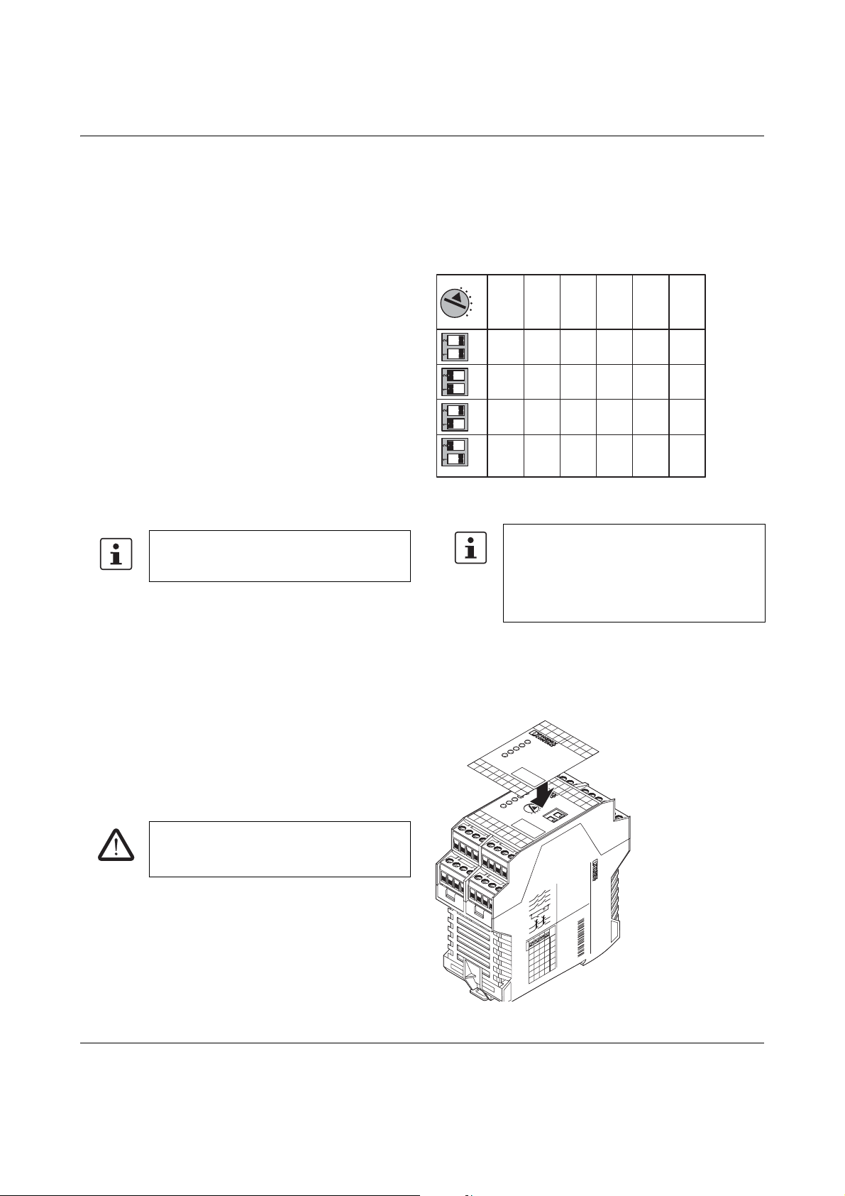
11.1 Setting the delay time
The delay time of 0.2s to 300s is set in 24increments via
the rotary switch and the DIP switch in the upper housing
part.
1Set a time period using the DIP switches.
2Set the desired delay time with the rotary switch.
Figure 4 Configuring the time delay
11.2 Protection against manipulation
Once the time has been set, the rotary switch and the DIP
switch can be protected against manipulation by covering
with the label provided.
Figure 5 Applying the label
Once configuration is complete, close the four
enable current paths and the Power, K1/K2
and K3(t)/K4(t) LEDS are illuminated.
WARNING: Danger due to incorrect delay
time!
Check the set delay time following installation.
If the rotary switch is modified during opera-
tion, the safety relay switches to configuration
mode and the LEDs flash. The safety relay is
only ready for operation again once the supply
voltage has been switched off and on again
and configuration has been carried out.
123
4
5
6
B
A
B
A
B
A
B
A
on
1
0,2
0,8
6,4
50
2
0,4
1,6
12,8
100
3
0,6
2,4
19,2
150
4
0,8
3,2
25
200
5
1
4
32
250
6
1,2
4,8
38
300
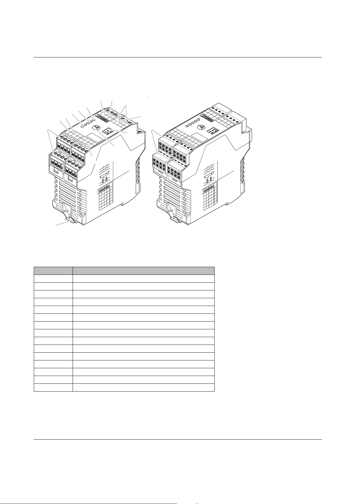
58 68 42
23 24
13
33 34
14
57 58 41
S12 S34 S33 S35
3334
2324
13
14
PSR-ESD-300
A1 S21 S22 A2
S10 S11 S11 S12
Y1 Y2
586842
576
741
Power
K1
K2
K3(t)
K4(t)
12
Time
B
A
on
1
6
3
4
5
2
PSR-SCP- 24DC/ESD/5X1/1X2/300
Order No.: 2981428
APPROVALS Serial No.
13 23 33 41 57 58
14 24 34 42 58 68
123456
0,2 0,4
0,8 1,6 2,4 3,2 4 4,8
6,4 12,8 19,2
50 100 150 200 250 300
0,6 0,8 1 1,2
25 32 38
on
S12 S34 S33 S35
33 34
232
4
13
14
PSR-ESD-300
A1 S21 S22 A2
S10 S11 S11 S12
Y1 Y2
5868 42
576741
Power
K1
K2
K3(t)
K4(t)
www.phoenixpowersupply.co.uk