2
1 Warning
⚠
Improper Use, Installation or Maintenance may result in serious injury or death.
⚠
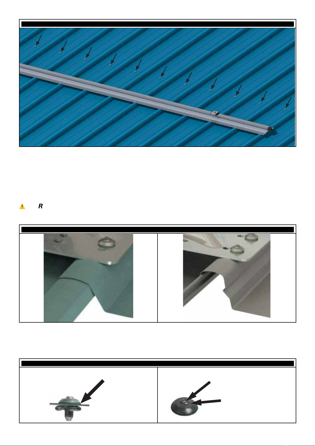
The building or structure for the anchorages should be assessed by an engineer to
ensure that the structure is adequate for X-Rail installation works.
⚠
SafetyLink's Height Safety Systems must only be installed as per our installation
guides, to structures as specified in the installation manual for each product.
⚠
All safety procedures must be complied with in accordance with the current safety
code(s) of practice(s) for working at heights in your region. Ensure safety at all times by
being attached to suitable anchor points and approved safety equipment or approved
scaffolding.
⚠
Installation is to be carried out by, or under the supervision of, a competent person.
⚠
A personal energy absorber or a fall-arrest device with a personal energy absorber
must be used in conjunction with all SafetyLink Anchorages and Lifeline systems.
⚠
Do not carry out any modifications on this system without written permission by
SafetyLink Pty Ltd.
2 Specification
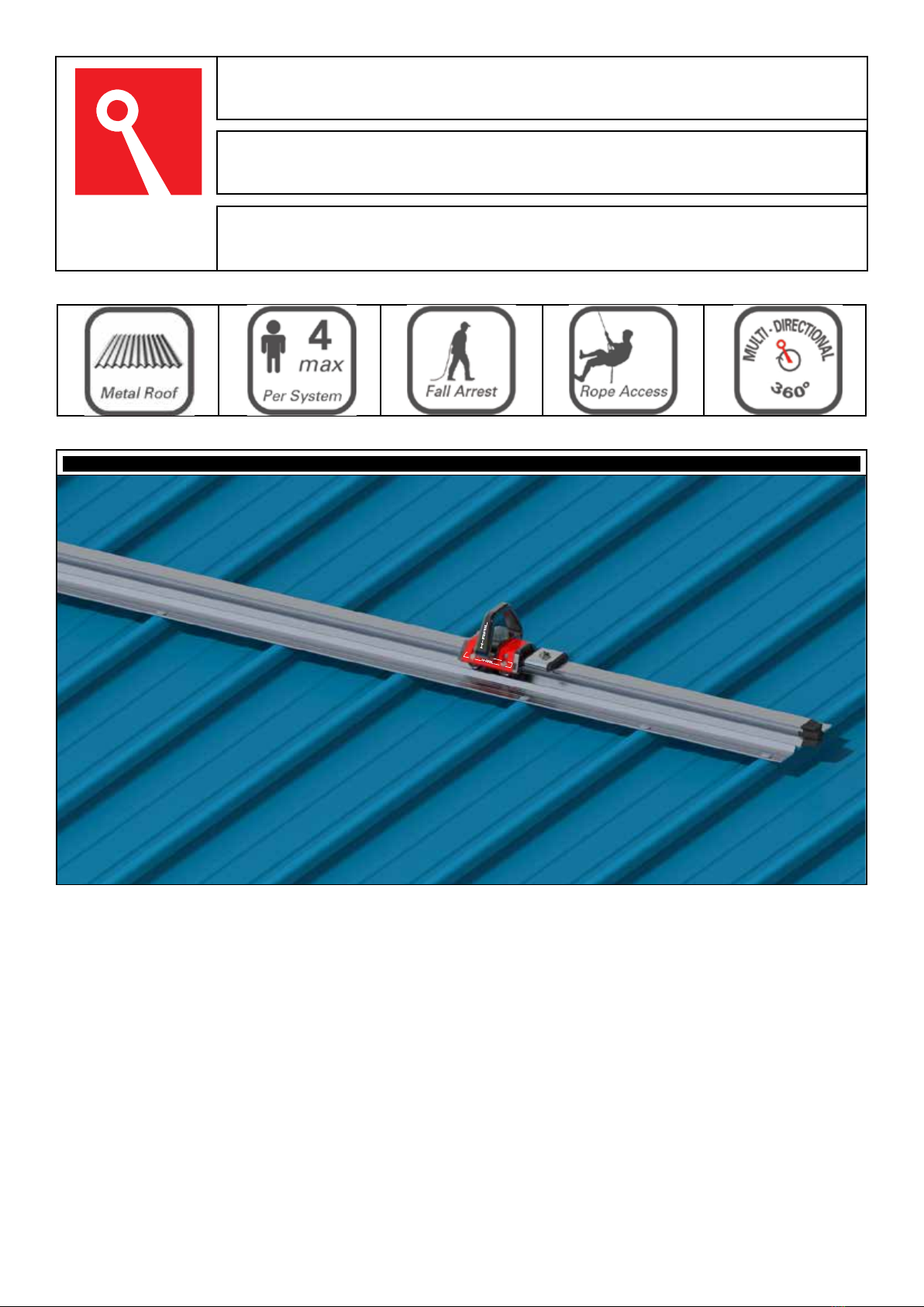
2.1 Description
The SafetyLink X-Rail is a Rigid Anchor Line suitable for use as part of a personal fall protection
system. The X-Rail offers a horizontal Rigid Anchor Line with one or multiple Mobile Anchor
Points for attaching to.
2.2 Standard
The X-Rail Rigid Anchor Line System is compliant with AS/NZS 1891.2, EN795:2012 and PD
CEN/TS 16415:2013.
2.3 User Rating
The X-Rail Rigid Anchor Line is rated for up to 4 users per system and in any span.
2.4 Material Specification
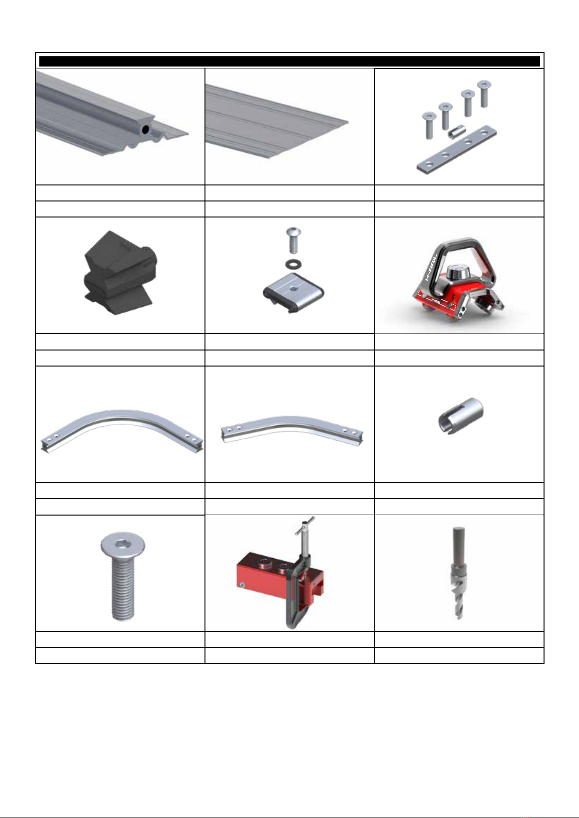
COMPONENT DESCRIPTION
Rail Aluminium 6000 series
Cross Plates Aluminium 6000 series
Joins Aluminium 6000 series
Fasteners Stainless steel 316
End Cap Nylon 66
End Stop Aluminium 6000 series, Rubberised Nylon
Shuttle Aluminium 6000 series, Stainless steel 316, Nylon 66