onlinecomponents.com
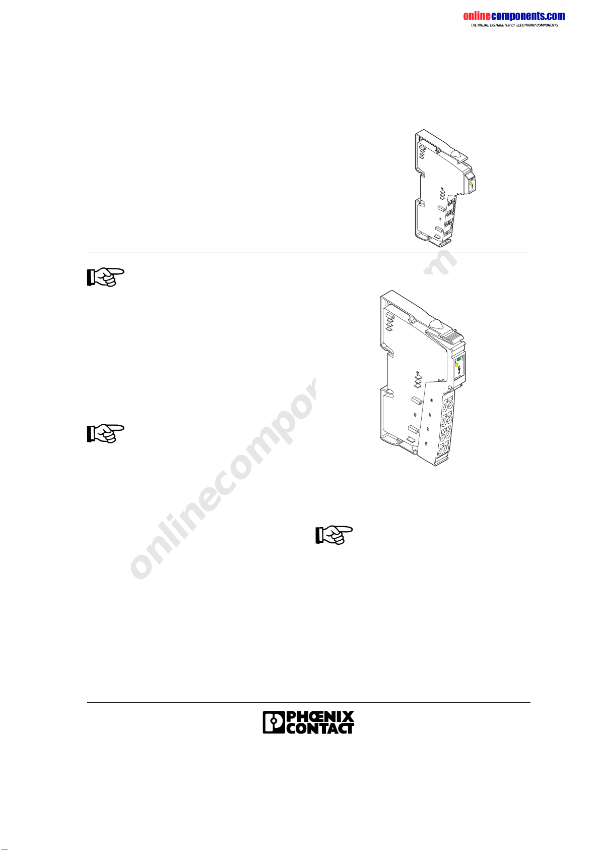
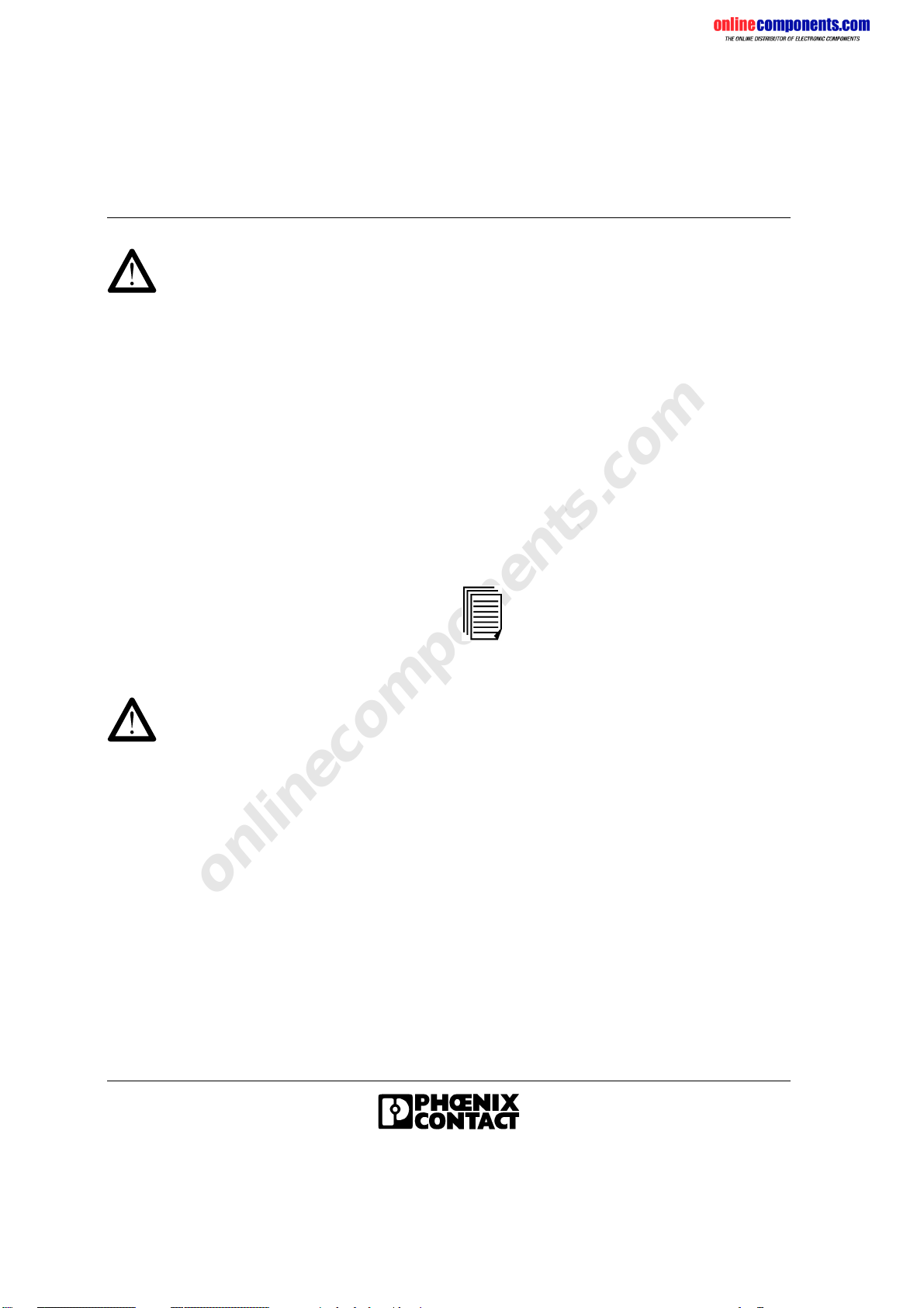
IB IL 24/230 DOR 1/W
85663BC01
Interference Suppression
Measures for Inductive Loads/
Switching Relays
Each electrical load is a combination of ohmic,
capacitive and inductive elements. When
switching these loads a larger or smaller load is
provided for the switching contact depending on
the weighting of the elements.
In practice, mainly loads with large inductive
portions, such as contactors, solenoid valves or
motors are used. Due to the energy stored in the
coils, voltage peaks of up to several thousand
volts may occur when the system is switched off.
These high voltages cause an arc, which may
destroy the controlling contact through material
evaporation and material transfer.
This rectangular type pulse beams
electromagnetic pulses via a wide frequency
area. Spectral parts reach the MHz area with a
great deal of power.
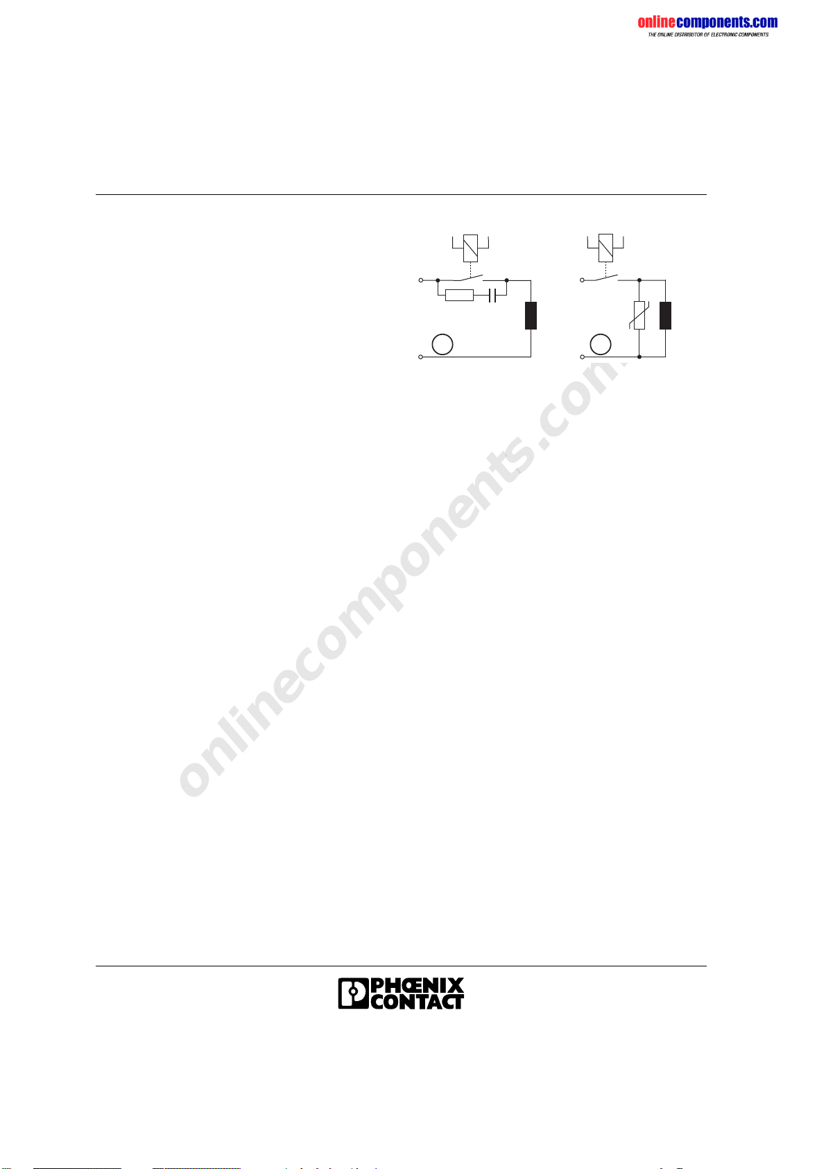
To prevent such arcs from occurring protective
circuits must be provided for contacts/loads. In
general, different wiring options are available:
–Protecting the contact
–Protecting the load
–Combination of both protection methods
Figure 8 Contact protection (A), load
protection (B)
If sized correctly, these circuit versions do not
differ greatly in their effectiveness. In general, a
protective measure should be implemented
directly at the source of the interference. The
following points indicate the advantages of load
protection:
–When the contact is open, the load is
electrically isolated from the operating
voltage.
–It is not possible for the load to be activated
or to "stick" due to undesired operating
currents, e.g., from RC elements.
–Shutdown voltage peaks cannot be induced
in control lines that run in parallel.
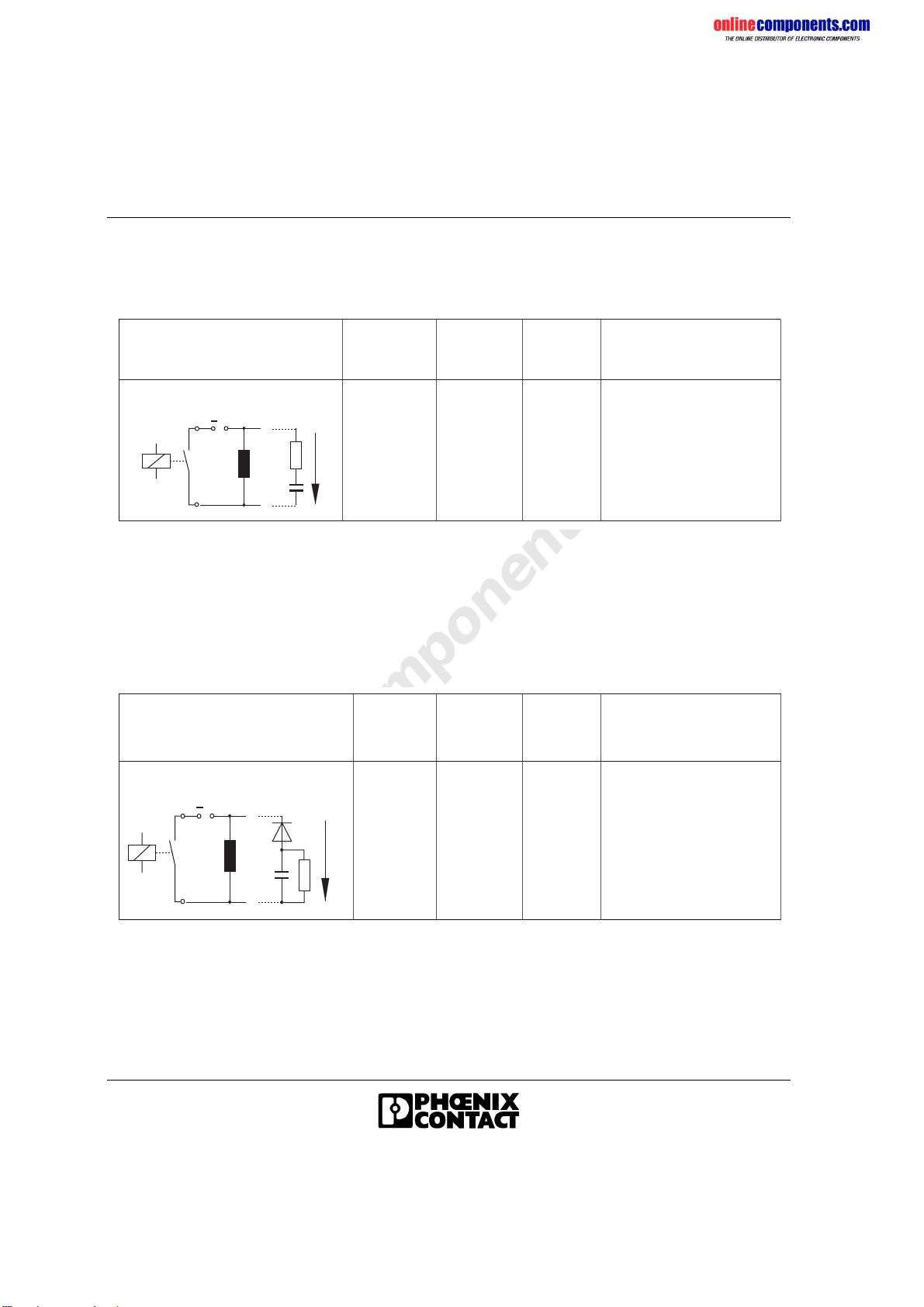
Phoenix Contact provide various solutions for
the protective circuit in terminal format or in
electronic housing (see CLIPLINE catalog or
TRABTECH catalog). Additional information is
available on request. Today most contact
manufacturers also offer diode, RC or varistor
elements, which can be snapped on. For
solenoid valves, it is possible to insert
connectors with an integrated protective circuit.
A B
5973A028