Phoenix Contact IB IL 24/230 DOR 4/W-PC User manual

6530B 1
IB IL 24/230 DOR 4/W-PC
IB IL 24/230 DOR 4/W-PC-PAC
03/2003
Data Sheet 6530B
Function
The terminal is designed for use within an Inline
station. It has four electrically isolated relay
changeover contacts. The terminal is suitable for
switching inductive and capacitive loads.
Features
– Safe isolation according to EN 50178
– Electrically isolated connection for four actuators
– Nominal current at the output: 3 A
– Total current of the terminal: 4 x 3 A = 12 A
– LED diagnostic and status indicators
Figure 1 IB IL 24/230 DOR 4/W-PC terminal with
connectors
The IB IL 24/230 DOR 4/W-PC and
IB IL 24/230 DOR 4/W-PC-PAC only
differ in the scope of supply (see
"Ordering Data" on page 17). Their
function and technical data are identical.
For greater clarity, the Order Designation
IB IL 24/230 DOR 4/W-PC is used
throughout this document.
This data sheet is only valid in association
with the IB IL SYS PRO UM E User
Manual or the Inline System Manual for
your bus system.
The terminal can be used in the SELV
area and in the AC area. Observe the
appropriate regulations and safety notes
when using the terminal in the AC area.
Please use the IB IL 24/230 DOR 4/W
terminal for switching voltages less than
12 V or currents less than 100 mA.
6 3 5 0 A 0 0 2
6 3 2 6 A 0 0 1
Inline Terminal
With Four Relay Changeover Contacts

IB IL 24/230 DOR 4/W-PC (-PAC)
26530B
Safety Notes Correct Usage
The terminal is only to be used within an Inline station
as specified in this data sheet and the
IB IL SYS PRO UM E User Manual or the Inline
System Manual for your bus system. Phoenix Contact
accepts no liability if the device is used for anything
other than its designated use.
Installation Instructions and
Notes
Safety notes for Inline terminals for
installation in voltage ranges outside
the SELV (AC area)
Only qualified personnel may work on
Inline terminals in the AC area.
Qualified personnel are people who,
because of their education, experience,
and instruction and their knowledge of
relevant standards, regulations, accident
prevention, and service conditions, have
been authorized by those responsible for
the safety of the plant to carry out any
required operations and who are able to
recognize and avoid any possible
dangers.
(Definitions for skilled workers according
to EN 50110-1:1996.)
The instructions given in the
IB IL SYS PRO UM E User Manual or
the Inline System Manual for your bus
system and in this data sheet must be
followed during installation and
startup.
Technical modifications reserved.
Dangerous voltage
Please note that there are dangerous
voltages when switching circuits that do
not meet SELV requirements.
Only remove and insert the AC terminals
when the power supply is disconnected.
When working on terminals and wiring,
always switch off the supply voltage and
ensure it cannot be switched on again.
Install the system according to the
requirements of EN 50178.
Please use grounded AC networks
Inline AC terminals must only be operated
in grounded AC networks.
Read the user manual
Please observe the installation
instructions and installation notes in the
IB IL SYS PRO UM E User Manual or the
Inline System Manual for your bus
system, especially the information about
the low voltage area.

IB IL 24/230 DOR 4/W-PC (-PAC)
6530B 3
Special Features of the
IB IL 24/230 DOR 4/W-PC Terminal
Loads up to 230 V can be switched using the
IB IL 24/230 DOR 4/W-PC terminal.
Switching Loads in the 230 V Area
To switch voltages outside the SELV area, an AC
area must be created corresponding to the installation
instructions and notes given in the user manual.
Switching Voltages That Are Not Available in the
Segment
A relay terminal can be used to switch voltages that
are not available in the segment in which the terminal
is located (e.g., switching 230 V AC within a 24 V DC
segment).
In this case, place a distance terminal before and after
the IB IL 24/230 DOR 4/W-PC terminal
(see "Ordering Data" on page 17). The isolating
distances between the individual areas are thus
maintained.
See also "Connection Examples" on page 6.
Please note that the
IB IL 24/230 DOR 4/W-PC terminal
interrupts the potential jumpers UM, US,
and GND (24 V area) as well as L and N
(120 V/230 V areas). If required, these
supply voltages must be reintroduced/
provided after the relay terminal using an
appropriate power terminal.
Operation on an AC network
Operate the terminal from a single phase
on an AC network.

IB IL 24/230 DOR 4/W-PC (-PAC)
46530B
General Description
Figure 2 IB IL 24/230 DOR 4/W-PC
with an appropriate connector
Function Identification
Red with lightning bolt
Housing/Connector Color
Gray housing
Gray connector
Local LED Diagnostic and Status Indicators
Terminal Assignment for Each Connector
In the corresponding connector IB IL SCN-8-AC-REL,
the adjacent contacts
1.2/2.2, 1.3/2.3, and 1.4/2.4 are jumpered.
It is therefore possible to transmit the power to
supply several relays of IB IL 24/230 DOR 4/W-PC
terminals from one connector to the next via a
jumper.
1 2
1
2
3
4
1
2
3
4
1 . 1
1 . 2
1 . 3
1 . 4
2 . 1
2 . 2
2 . 3
2 . 4
6 5 3 0 A 0 0 3
12
D
D O R 4 / W
34
Des. Color Meaning
DGreen Diagnostics
1, 2,
3, 4
Yellow Output status indicator
(relay has picked up)
Terminal
Points
Assignment
1.1, 2.1 Not used
(no contact present)
1.2, 2.2 Relay N/C contact
1.3, 2.3 Relay main contact
1.4, 2.4 Relay N/O contact
Please note that the current at one
terminal point must not exceed 8 A.

IB IL 24/230 DOR 4/W-PC (-PAC)
6530B 5
Internal Circuit Diagram
Figure 3 Internal wiring of the terminal points
Key:
L o c a l b u s
UL
O P C
4
4
6 5 3 0 A 0 0 4
Protocol chip (bus logic including
voltage conditioning)
LED
Terminal point, without metal contact
Relay
FE or PE depending on the area in
which the terminal is used
Electrically isolated area
I/O area including relay contact isolated
from the logic area including the relay
coil through "safe isolation" according
to EN 50178.
OPC Other symbols are explained in the
IB IL SYS PRO UM E User Manual or in
the Inline System Manual for your bus
system.

IB IL 24/230 DOR 4/W-PC (-PAC)
66530B
Connection Examples
Connecting Actuators
Figure 4 Typical connection of actuators
Figure 5 Output relay contacts
1 2
1
2
3
4
1
2
3
4
1 2
1
2
3
4
1
2
3
4
1 2
1
2
3
4
1
2
3
4
1 2
1
2
3
4
1
2
3
4
12
D
D O R 4 / W
34
6 3 2 6 A 0 0 5
123 4
N / C
c o n t a c t
M a i n
c o n t a c t
N /O
c o n t a c t
N /C
c o n t a c t
M a i n
c o n t a c t
N /O
c o n t a c t
1 . 2
1 . 4
1 . 3
M a i n
c o n t a c t
5 6 6 3 A 0 0
N / C
c o n t a c t
N / O
c o n t a c t

IB IL 24/230 DOR 4/W-PC (-PAC)
6530B 7
Switching Voltages That Are Not Available in the
Segment
Figure 6 Example: Switching 230 V within a
24 V area
See also "Special Features of the IB IL 24/
230 DOR 4/W-PC Terminal" on page 3.
Switching Voltages That Are Available in the
Segment
Figure 7 Switching 24 V within a 24 V area
1 24 V area consisting of station head and
I/O terminals
2 IB IL 24/230 DOR 4/W-PC terminal
separated from the 24 V area by distance
terminals
3 24 V area consisting of a power terminal and
I/O terminals
Distance terminals can also be used to
switch a 24 V channel within a 230 V area.
1 2
1
2
3
4
1
2
3
4
1
6 3 2 6 A 0 0 6
1 2
1
2
3
4
1
2
3
4
1 2
1
2
3
4
1
2
3
4
12
D
D O R 4 / W
34
1 2
1
2
3
4
1
2
3
4
1 2
1
2
3
4
1
2
3
4
1 2
1
2
3
4
1
2
3
4
1 2
1
2
3
4
1
2
3
4
1 2
1
2
3
4
1
2
3
4
32
1 2
1
2
3
4
1
2
3
4
1 2
1
2
3
4
1
2
3
4
1 2
1
2
3
4
1
2
3
4
1 2
1
2
3
4
1
2
3
4
U M
P W R I N
The distance terminals are not required to
switch a 24 V channel within a 24 V area
or to switch a 230 V channel within a
230 V area.
1 24 V area consisting of station head and
I/O terminals
2 IB IL 24/230 DOR 4/W-PC terminal
3 24 V area consisting of a power terminal and
I/O terminals
1
6 3 2 6 A 0 0 7
1 2
1
2
3
4
1
2
3
4
12
D
D O R 4 / W
34
1 2
1
2
3
4
1
2
3
4
1 2
1
2
3
4
1
2
3
4
1 2
1
2
3
4
1
2
3
4
1 2
1
2
3
4
1
2
3
4
1 2
1
2
3
4
1
2
3
4
32
1 2
1
2
3
4
1
2
3
4
1 2
1
2
3
4
1
2
3
4
1 2
1
2
3
4
1
2
3
4
1 2
1
2
3
4
1
2
3
4
U M
P W R I N

IB IL 24/230 DOR 4/W-PC (-PAC)
86530B
Interference Suppression Measures
on Inductive Loads/Switching Relay
Each electrical load is a mixture of ohmic, capacitive,
and inductive elements. Depending on the proportion
of the element, switching these loads results in a
larger or smaller load on the switch contact.
In practice, loads are generally used with a large
inductive element, such as contacts, solenoid valves,
motors, etc. Due to the energy stored in the coils,
voltage peaks of up to several thousand volts may
occur when the system is switched off.
These high voltages cause an arc, which may destroy
the controlling contact through material evaporation
and material transfer.
This pulse, which is similar to a square wave pulse,
emits electromagnetic pulses over a wide frequency
range with a large amount of power and with spectral
elements reaching several MHz.
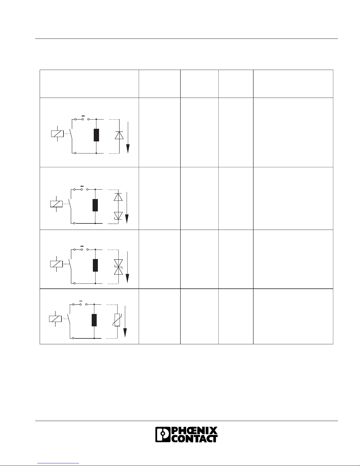
To prevent such arcs from occurring it is necessary to
fit the contacts/loads with protective circuits. The
following protective circuits can be used:
–Contact protective circuit
–Load protective circuit
–Combination of both protective circuits
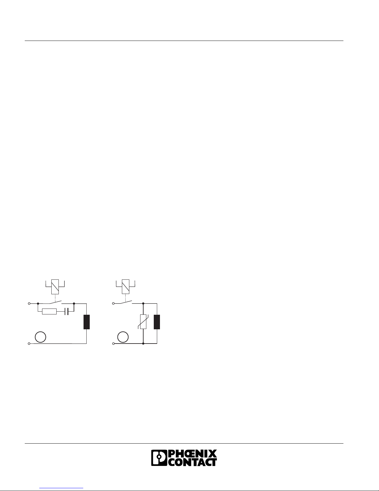
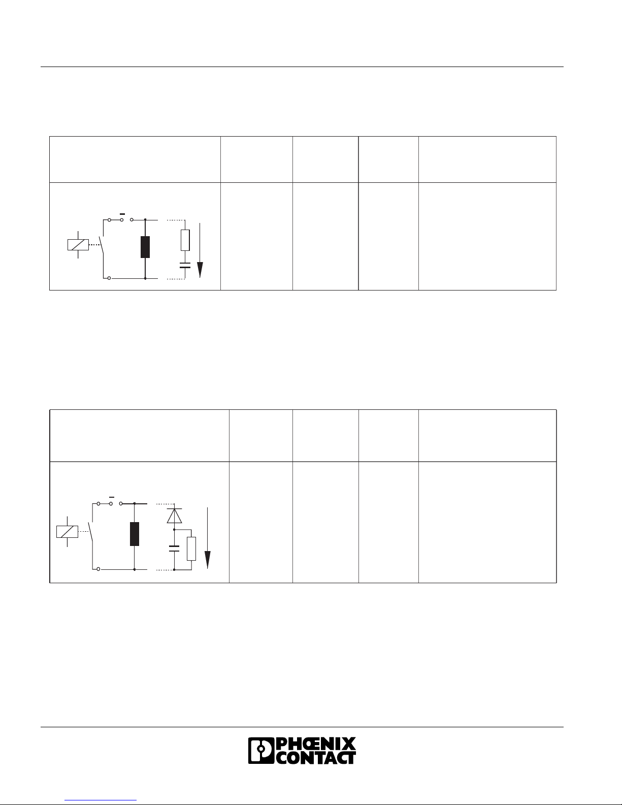
Figure 8 Contact protective circuit (A), load
protective circuit (B)
If sized correctly, these circuit versions do not differ
greatly in their effectiveness. In principle, a protective
measure should be directly implemented at the
source of the interference. In addition, the following
points should be observed for a load protective circuit:
–When the contact is open, the load is electrically
isolated from the operating voltage.
–It is not possible for the load to be activated or to
"stick" due to undesired operating currents,
e.g., from RC elements.
–Shutdown voltage peaks cannot be coupled in
control lines that run in parallel.
Phoenix Contact provides protective circuit solutions
in terminal format or in electronic housing (see the
"CLIPLINE" catalog or "TRABTECH" catalog).
Additional information is available on request. In
addition to this, today the majority of contact
manufacturers offer diode, RC or varistor elements
that can be snapped on. For solenoid valves,
connectors with an integrated protective circuit can be
used.
A B
5 7 3 A 0 2 8

IB IL 24/230 DOR 4/W-PC (-PAC)
6530B 9
Circuit Versions
P r o t e c t i n g t h e l o a d A d d i t i o n a l
d e l a y
D e f i n e d
I n d u c t i o n
V o l t a g e
L i m i t a t i o n
B i p o l a r
E f f e c t i v e
A t t e n u a t i o n
A d v a n t a g e s /
D i s a d v a n t a g e s
L o n g
M e d i u m
t o s h o r t
M e d i u m
t o s h o r t
M e d i u m
t o s h o r t
Y e s ( U ) N o
A d v a n t a g e s :
- E a s y i m p l e m e n t a t i o n
- C o s t - e f f e c t i v e
- P e r m i t t e d
- U n c r i t i c a l s i z i n g
- L o w i n d u c t i o n v o l t a g e
D i s a d v a n t a g e s :
- A t t e n u a t i o n o n l y v i a
l o a d r e s i s t o r
- H i g h d e l a y
N o
A d v a n t a g e s :
- U n c r i t i c a l s i z i n g
D i s a d v a n t a g e s :
- A t t e n u a t i o n o n l y
a b o v e U Z D
Y e s
A d v a n t a g e s :
- C o s t - e f f e c t i v e
- U n c r i t i c a l s i z i n g
- L i m i t s p o s i t i v e p e a k s
- S u i t a b l e f o r A C v o l t a g e
D i s a d v a n t a g e s :
- A t t e n u a t i o n o n l y
a b o v e U Z D
A d v a n t a g e s :
- H i g h p o w e r a b s o r p t i o n
- U n c r i t i c a l s i z i n g
- S u i t a b l e f o r A C v o l t a g e
D i s a d v a n t a g e s :
- A t t e n u a t i o n o n l y
a b o v e U V D R
Y e s
+
UD
Load
D i o d e
+
UZ D
Load
S e r i e s c o n n e c t i o n d i o d e /
z e n e r d i o d e
+
UZ D
Load
( ~ )
( ~ )
S u p p r e s s o r d i o d e
+
UV D R
Load
( ~ )
( ~ )
V D R
V a r i s t o r
5 6 6 3 A 0 2
D
Y e s ( U )
Z D
Y e s ( U )
Z D
Y e s ( U )
V D R

IB IL 24/230 DOR 4/W-PC (-PAC)
10 6530B
RC Circuit Versions
RC Connected in Series:
Sizing:
RC Parallel Circuit With Series Diode
Sizing:
P r o t e c i t n g t h e L o a d A d d i t i o n a l
D e l a y
D e f i n e d
I n d u c t i o n
V o l t a g e
L i m i t a t i o n
B i p o l a r
E f f e c t i v e
A t t e n u a t i o n
A d v a n t a g e s / D i s a d v a n t a g e s
5 6 6 3 A 0 3 0
M e d i u m
t o s h o r t
N o Y e s
A d v a n t a g e s :
- H F a t t e n u a t i o n v i a p o w e r s t o r e
- S u i t a b l e f o r A / C v o l t a g e
- L e v e l - i n d e p e n d e n t a t t e n u a t i o n
- R e a c t i v e - c u r r e n t c o m p e n s a t i n g
+
UR C
Load
( ~ )
( ~ )
R
C
/ C c o m b i n a t i o n
D i s a d v a n t a g e s :
- E x a c t d i m e n s i o n r e q u i r e d
- H i g h i n r u s h c u r r e n t
–Capacitor: C ≈ LLoad/4 ×RLoad2
–Resistor: R ≈ 0.2 ×RLoad
P r o t e c t i n g t h e l o a d A d d i t i o n a l
D e l a y
D e f i n e d
I n d u c t i o n
V o l t a g e
L i m i t a t i o n
B i p o l a r
E f f e c t i v e
A t t e n u a t i o n
A d v a n t a g e s / D i s a d v a n t a g e s
5663A031
M e d i u m
t o s h o r t N o Y e s
A d v a n t a g e s :
- H F a t t e n u a t i o n v i a
p o w e r s t o r e
- L e v e l - i n d e p e n d a n t a t t e n u a t i o n
- C u r r e n t i n v e r s i o n n o t p o s s i b l e
D i s a d v a n t a g e s :
- E x a c t d i m e n s i o n r e q u i r e d
- O n l y s u i t a b l e f o r D C v o l t a g e
+
U
R C
Load
( ~ )
( ~ )
R
C
/ C c o m m u n i c a t i o n w i t h d i o d e
–Capacitor: C ≈ LLoad/4 ×RLoad2
–Resistor: R ≈ 0.2 ×RLoad

IB IL 24/230 DOR 4/W-PC (-PAC)
6530B 11
Switching AC/DC Loads
Switching Large AC Loads
When switching large AC loads, the relay can be
operated up to the corresponding maximum values for
switching voltage, current, and power. The arc that
occurs during shutdown depends on the current,
voltage, and phase angle. This shutdown arc switches
off automatically the next time the load current passes
through zero.
In applications with an inductive load, an effective
protective circuit must be provided, otherwise the life
of the system will be reduced considerably.
To prolong the life of the IB IL 24/230 DOR 4/W-PC
terminal as mush as possible when using lamp loads
or capacitive loads, the current peak must not exceed
6 A when the load is switched on.
Switching Large DC Loads
In DC operation, a relay can only switch a relatively
low current compared with the maximum permissible
alternating current. This maximum direct current value
is also highly dependent on the voltage and is
determined in part by design conditions, such as the
contact distance and contact opening speed.
The corresponding current and voltage values are
shown in Figure 9.
Figure 9 DC load limiting curve
(REL-SNR-1XU/G 5 GOLD relay)
An unattenuated inductive load further reduces the
values given here for switching currents. The energy
stored in the inductivity can cause an arc to occur
which forwards the current via the open contacts.
Using an effective contact protective circuit in relay
contacts with the same life enables you to switch
currents that are virtually the same as with ohmic
loads.
Additional technical data is available on request.
ISwitching current in A
USwitching voltage in V
Definition of the load limiting curve: For 1000 cycles,
no constant arc should occur with a burning life
>10ms.
If it is permitted to switch higher DC loads,
several relay contacts can be switched
in parallel.
1
1 0
1 0 0
1 0 0 0
V
U
I
0 . 1 1 1 0
5 6 6 3 A 0 1 3
A

IB IL 24/230 DOR 4/W-PC (-PAC)
12 6530B
Programming Data/Configuration
Data
INTERBUS
Other Bus Systems
Process Data
Assignment of Terminal Points to OUT Process
Data
ID code BDhex (189dec)
Length code 41hex
Process data channel 4 bits
Input address area 0 bits
Output address area 4 bits
Parameter channel (PCP) 0 bits
Register length (bus) 4 bits
For the configuration data of other bus
systems, please refer to the appropriate
electronic device data sheet (GSD, EDS).
(Byte.bit)
view
Bit 0.3 0.2 0.1 0.0
AssignmentSlot 4321
N/C contact 1.2 1.2 1.2 1.2
Main contact 1.3 1.3 1.3 1.3
N/O contact 1.4 1.4 1.4 1.4
Status
indicator
LED 4321
If the bits are set to 1, the corresponding
N/O contact is closed.
The LEDs light up, if the corresponding
N/O contact is closed.
For the assignment of the illustrated
(byte.bit) view for your INTERBUS control
or computer system, please refer to data
sheet DB GB IBS SYS ADDRESS,
PartNo.9000999.

IB IL 24/230 DOR 4/W-PC (-PAC)
6530B 13
Technical Data
General Data
Order Designation (Order No.) IB IL 24/230 DOR 4/W-PC-PAC (28 62 18 1)
IB IL 24/230 DOR 4/W-PC (28 60 41 3)
Housing dimensions (width x height x depth) 48.8 mm x 120 mm x 71.5 mm
(1.921in. x 4.724 in. x 2.815 in.)
Weight 138 g (without connectors)
Operating mode Process data mode with 4 bits
Type of actuator connection To an electrically isolated relay changeover contact
Permissible temperature (operation) -25°C to +55°C (-13°F to +131°F)
Permissible temperature (storage/transport) -25°C to +85°C (-13°F to +185°F)
Permissible humidity (operation) 75% on average, 85% occasionally
Permissible humidity (storage/transport) 75% on average, 85% occasionally
Permissible air pressure (operation) 80 kPa to 106 kPa
(up to 2000 m [6562 ft.] above sea level)
Permissible air pressure (storage/transport) 70 kPa to 106 kPa
(up to 3000 m [9843 ft.] above sea level)
Degree of protection IP 20 according to IEC 60529
In the range from -25°Cto+55°C (-13°F to +131°F) appropriate measures against increased
humidity (> 85%) must be taken.
For a short period, slight condensation may appear on the outside of the housing if,
for example, the terminal is brought into a closed room from a vehicle.
Mechanical Requirements (Deviation From the Inline Specifications)
Vibration test
sinusoidal vibrations according to
IEC 60068-2-6; EN 60068-2-6
2g load, 2 hours for each space direction
Shock test according to
IEC 60068-2-27; EN 60068-2-27
2g load for 11 ms, half sinusoidal wave,
three shocks in each space direction and orientation
Interface
Local bus Through data routing
Power Consumption
Communications power 7.5 V
Current consumption from the local bus off/on 22 mA/187 mA
Power consumption from the local bus 0.17 W/1.4 W
Supply of the Module Electronics and I/O Through Bus Terminal/Power Terminal
Connection method Through potential routing

IB IL 24/230 DOR 4/W-PC (-PAC)
14 6530B
Relay output
Number 4
Contact material AgSnO2, hard gold-plated
Contact resistance 50 mΩat 100 mA/6 V
Limiting continuous current
(at maximum ambient temperature)
3 A
Maximum switching voltage 253 V AC, 250 V DC
Maximum switching power (AC/DC) 750 VA (see derating)
Minimum load 5 V; 10 mA
Switching current at 30 V DC 3 A
Switching current at 250 V DC 0.15 A
Maximum inrush current peak for lamp loads and
capacitive loads
6 A for T = 200 µs
Nominal power consumption of the coil (at 20°C [68°F]) 330 mW from the 7.5 V supply
Resistance of the coil (at 20°C [68°F]) 119 Ω±12 Ω
Maximum switching frequency (without load) 1200 cycles/minute
Maximum switching frequency (with nominal load) 6 cycles/minute
Response delay 5 ms, typical
Bouncing time 5 ms, typical
Release time 6 ms, typical
Mechanical life 2 x 10⁷cycles
Electrical life 105cycles
(at 20 cycles/minute)
Common potentials All contacts electrically isolated
See also the Table entitled "Maximum Switching Current for Ohmic Load Depending on the
Switching Voltage" on page 15.

IB IL 24/230 DOR 4/W-PC (-PAC)
6530B 15
Maximum Switching Current for Ohmic Load Depending on the Switching Voltage
(With Direct Voltage)
Switching Voltage (V DC) Switching Current (A)
53.0
10 3.0
20 3.0
30 3.0
40 1.0
50 0.4
60 0.3
70 0.26
80 0.23
90 0.215
100 0.2
150 0.18
200 0.165
250 0.155
Load Current (ILin A) as a Function of the Switching Voltage (Uswitch in V)
0
0 . 5
1
1 . 5
2
2 . 5
3
1 0 2 0 3 0 4 0 5 0 6 0 7 0 8 0 0 100 150 200 250
5 6 6 3 A 0 0 4
IL
A
Us w i t c h
V

IB IL 24/230 DOR 4/W-PC (-PAC)
16 6530B
Maximum Switching Current Depending on the Temperature (With Alternating Voltage)
Load Current (ILin A) as a Function of the Ambient Temperature (TAin °C)
Power Dissipation
Formula to Calculate the Power Dissipation in the Terminal
PEL = PBUS + (PREL) + PL
PEL = 0.17 W + 4 x ((0.31 W) + IL2x 0.04 Ω)
Where
PEL Total power dissipation in the terminal
PBUS Power dissipation through bus operation
PREL Power dissipation of the relay coil
PLPower dissipation through the load current via the contacts
ILLoad current of the output
Power Dissipation of the Housing Depending on the Ambient Temperature
PHOU = 2.7 W -25°C (-13°F) < TA≤+25°C (+77°F)
PHOU = 2.7 W - ((TA- 25°C [77°F]) x 0.02 W/°C) +25°C (+77°F) < TA≤+55°C (+131°F)
Where
PHOU Permissible power dissipation of the housing
TAAmbient temperature
With a switching current of 3 A, the switching voltage with alternating current must not exceed
253 V AC. Observe the derating.
0
0 . 5
1
1 . 5
2
2 . 5
3
1 0 2 0 3 0 4 0 5 0 5 5
6 3 2 6 A 0 0 8
IL
A
TA
4 5 ° C
For N/C contacts, the term PREL is omitted from the formula.

IB IL 24/230 DOR 4/W-PC (-PAC)
6530B 17
Ordering Data
Safety Measures
None
Error Messages to the Higher-Level Control or Computer System
None
Air and Creepance Distances (According to EN 50178, VDE 0109, VDE 0110)
Isolating Distance Clearance Creepance
Distance
Test Voltage
Relay contact/bus logic ≥5.5 mm
(0.217 in.)
≥5.5 mm
(0.217 in.)
4 kV, 50 Hz, 1 min.
Contact/contact ≥3.1 mm
(0.122 in.)
≥3.1 mm
(0.122 in.)
1 kV, 50 Hz, 1 min.
Contact/PE ≥3.1 mm
(0.122 in.)
≥3.1 mm
(0.122 in.)
1 kV, 50 Hz, 1 min.
Description Order Designation Order No.
Terminal with four relay changeover contacts;
including connectors and labeling fields
IB IL 24/230 DOR 4/W-PC-PAC 28 62 18 1
Terminal with four relay changeover contacts IB IL 24/230 DOR 4/W-PC 28 60 41 3
Connector with seven terminals, spring-cage connection
(gray, w/o color print);
pack of 10
IB IL SCN-8-AC-REL 27 40 29 0
Distance terminals
(isolation of various voltage areas);
pack of 1 set (2 pcs.)
IB IL DOR LV-SET 27 42 64 1
Connector for IB IL DOR LV-SET;
pack of 1 set (2 pcs.)
IB IL DOR LV-PLSET 27 42 66 7
"Configuring and Installing the INTERBUS Inline Product
Range" User Manual
IB IL SYS PRO UM E 27 43 04 8
Four connectors are required for the complete fitting of the IB IL 24/230 DOR 4/W-PC-PAC
terminal.
Make sure you always use the latest documentation.
This is available on the Internet at www.phoenixcontact.com.

IB IL 24/230 DOR 4/W-PC (-PAC)
18 6530B
© Phoenix Contact 03/2003
Technical modifications reserved.
TNR 90 11 32 6
Phoenix Contact GmbH & Co. KG
Flachsmarktstr. 8
32825 Blomberg
Germany
+49 - 52 35 - 30 0
+49 - 52 35 - 34 12 00
www.phoenixcontact.com
Worldwide Locations:
www.phoenixcontact.com/salesnetwork
This manual suits for next models
1
Table of contents
Other Phoenix Contact Touch Terminal manuals