Phuel 145-4427-HV0 User manual

OPS-4427 Rev A
Unit 17 Denmore Industrial Estate, Denmore Road, Bridge of Don, Aberdeen AB23 8JW
User Manual
15K Grease Head
8 ¾-4 Quick Union (5’’ Seal Bore)
This Manual Covers the Following Part Numbers:
145-4427-HV0

User Manual
Grease Head
OPS-4427 Rev A i
Table of Contents
Revision History ...........................................................................................ii
Safety.............................................................................................................. iii
1Introduction...............................................................................................1
1.1 General..............................................................................................1
1.2 Product Identification.........................................................................1
2Technical Specification.............................................................................2
3Technical ..................................................................................................4
3.1 Description.........................................................................................4
3.2 Key Product Features........................................................................6
4Operation..................................................................................................8
4.1 Lifting and Handling...........................................................................8
4.2 Setting Up..........................................................................................8
4.3 Pre Job............................................................................................10
4.4 During Job.......................................................................................10
4.5 Post Job...........................................................................................11
5Maintenance...........................................................................................12
5.1 Introduction......................................................................................12
5.2 Schedule..........................................................................................12
5.3 Safety ..............................................................................................13
5.4 Redress Procedure..........................................................................13
5.5 Maintenance Record Sheet .............................................................18
6Testing....................................................................................................19
7Parts List and Drawings..........................................................................20
8Spares ....................................................................................................25
Table 1: Technical Data...................................................................................2
Table 2: Recommended Grease Head Arrangement (Guidance only).............5
Table 3: Maintenance Record........................................................................18
Table 4: Parts List 145-4427-HV0..................................................................21
Table 5 : Redress Kit Part No RDK-4427-HV0 ..............................................25
Figure 1: Grease Head Safety ........................................................................ iii
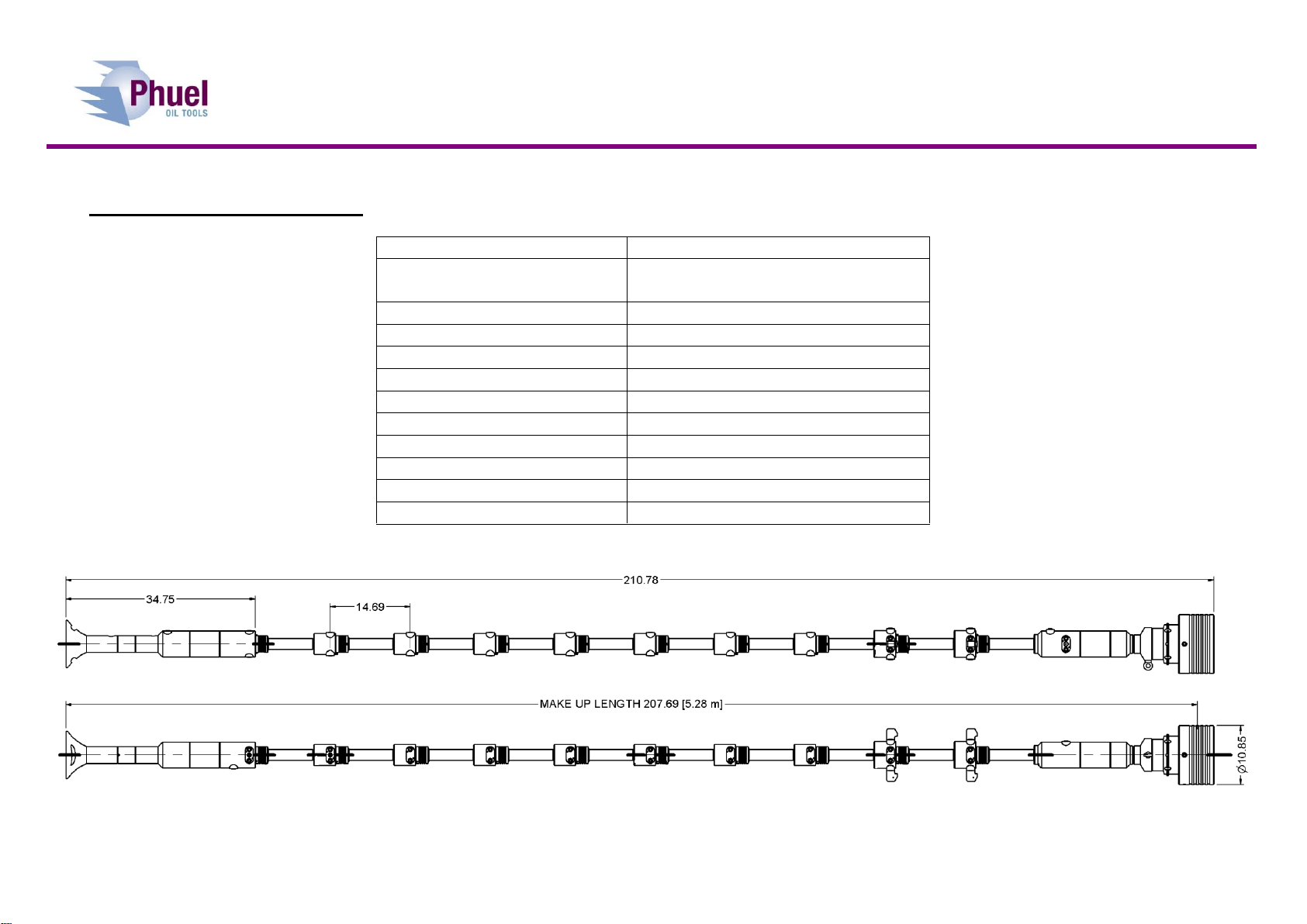
Figure 2: Grease Head ....................................................................................2
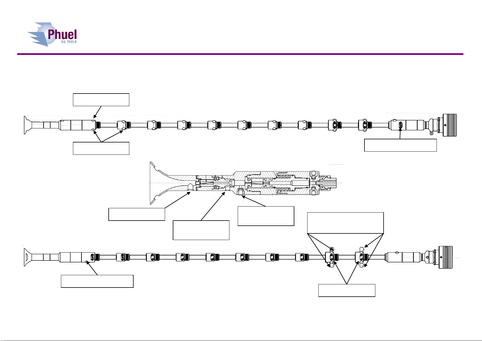
Figure 3: Grease Head Connections................................................................3
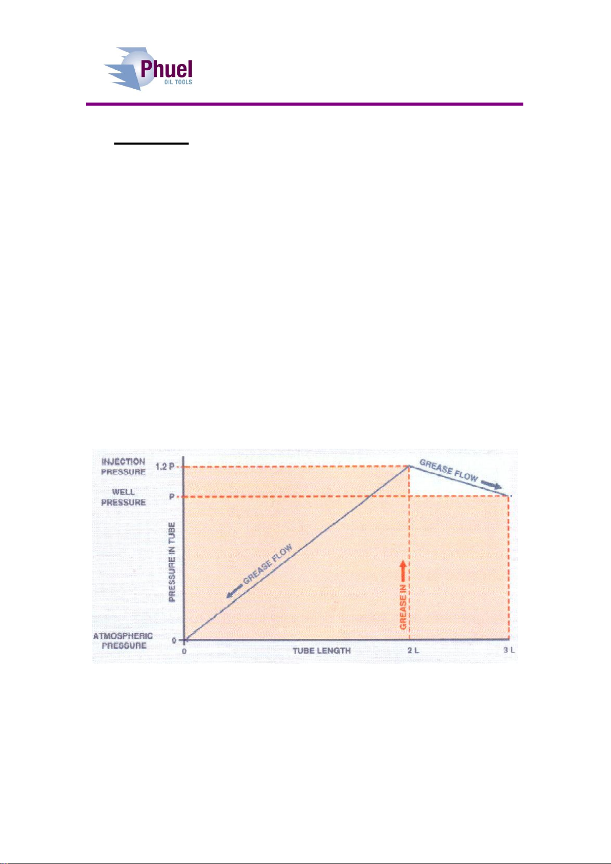
Figure 4: Pressure gradient inside the flow tube assembly..............................4
Figure 5: Couettes flow equation .....................................................................5
Figure 6: Fast Collar ........................................................................................6
Figure 7: Fitting the packing.............................................................................9
Figure 8: Assembly guide –part 1 .................................................................15
Figure 9: Assembly guide –part 2 .................................................................16
Figure 10: Assembly guide –part 3 ...............................................................17
Figure 11: Grease Head Assembly................................................................22
Figure 12: Grease Head Assembly Detail......................................................24

User Manual
Grease Head
OPS-4427 Rev A ii
Revision History
Issue, Release Date
Description
Rev A, 22 Feb. 12
Initial Issue

User Manual
Grease Head
OPS-4427 Rev A iii
Safety
WARNING: Trapped air requires considerable time to compress and
when it is compressed is highly dangerous. It has enough stored
energy to separate parts with considerable force.
Seals in high-pressure vessels are also susceptible to explosive
decompression; the O-rings or rubber gaskets used to seal pressurised
pipelines tend to become saturated with high-pressure gases. If the
pressure inside the vessel is suddenly released, then the gases within
the rubber gasket may expand violently, causing blistering or explosion
of the material.
All pressure equipment has a particular pressure rating and care must be
taken to ensure that no item is used in a situation that may cause its working
pressure to be exceeded.
All personnel involved in pressure testing must be formally trained, competent
and utilising the appropriate PPE.
Safe-Lok devices, where fitted, should be checked for positional security to
avoid unnecessary movement of the collar
Ensure the identification band/plate is fitted and is displaying the correct
information as per the Tag Sheet/Index
This equipment and the equipment it is attached to is heavy never position
yourself below a suspended load
Figure 1: Grease Head Safety
Finger, Glove and
loose clothing trap
area

User Manual
Grease Head
OPS-4427 Rev A 1
1 Introduction
1.1 General
Phuel has transformed the greasehead functionality with the innovation of
using what are essentially small quick union connections on the flow tube
housings. This vastly improves eases and speeds up the redressing
operations and allows the operator to align his hydraulic connection with ease.
The design utilises standard flow tubes and comes complete with ball check
valves and chemical injection facilities. The Phuel greasehead is designed for
up to 15,000psi working pressure and H2S service.
This user manual serves as an introduction to the equipment and contains the
relevant specifications, operation, planning and maintenance instructions,
parts list and drawings.
1.2 Product Identification
Phuel products are identified by a unique serial number that facilitates full
product traceability. Each product is supplied with a documentation pack that
contains product certification and material/inspection reports. The serial
number is always etched on the surface of the product but can sometimes be
difficult to find or read after painting. A customer identification number is also
included to allow the customer to track the asset in their system.
A stainless steel band secures the nameplate tag that is stamped with the
information shown below. This tag should be located in the first instance to
ensure that this manual refers to the correct equipment.

User Manual
Grease Head
OPS-4427 Rev A 2
2 Technical Specification
Part Number
145-4427-HV0
Connections
8 ¾-4’’ Quick Union (5’’ Seal Bore)
2’’ NPT Male Top Thread
Maximum Working Pressure
15,000 Psi
Design Test Pressure
22,500 Psi
Service
H2S
Weight
610 lbs / 277 kg
Overall Length
210.78’’ / 5.35m
Make Up Length
207.64’’ / 5.28m
Port Connections
9/16 Autoclave MP
Line Wiper Return
½” NPT
Piston Pressure
½” NPT
Earthing Tapped Hole
M12 x 12mm deep
Table 1: Technical Data
Figure 2: Grease Head

User Manual
Grease Head
OPS-4427 Rev A 3
Figure 3: Grease Head Connections
Grease Monitor
Grease Injection with
Check Valve
Hydraulic Pack-Off
Hydraulic Pack-Off
Grease Monitor
Grease Return
Line Wiper Air
Inlet
Line Wiper
Return
Optional Drain

User Manual
Grease Head
OPS-4427 Rev A 4
3 Technical
3.1 Description
The grease injection control head (greasehead) provides a pressure seal
around stationary or moving wireline that is run into or out of wells to prevent
the escape of well fluids to the environment. The assembly consists of a
hydraulic pack off and a series of flow tube assemblies.
The flow tube assembly consists of a number of close fitting steel tubes
through which the wire line passes. Each flow tube is approximately 14” long
and these are slipped onto the wire and connected together with the fast collar
connection to build up the required length. Viscous grease is injected between
the bore of the flow tube and the outside of the wire and travels along the
length of the flow tube stack creating a pressure drop. Grease injection
pressure can then be increased to about 25% more than the well pressure to
create a liquid seal that allows the wire to move but prevents the escape of
well fluids. The inside diameter of the flow tubes needs to be from 0.003” to
0.008” larger than the actual wire diameter for the seal to be effective so the
flow tubes must be selected based on the wire being used.
Figure 4: Pressure gradient inside the flow tube assembly
The length of flow tube required depends on the well pressure, the wire size,
the flow tube size, the grease viscosity and pump rate and the effectiveness of
the seal will depend on the pull out speed of the wire. The relationship for the
pressure drop can be expressed mathematically by Couettes flow equation.
This shows that the clearance between the wire and the flow tube has a great
effect on the pressure drop created as so this is the most important parameter
to consider.

User Manual
Grease Head
OPS-4427 Rev A 5
Figure 5: Couettes flow equation
The actual diameter of the wire must be measured and recorded to allow the
correct diameter of flow tube to be selected. The condition of the wire must
also be considered as mud or rust ingress can cause the wire to swell.
Consideration also needs to be given to the wear of the flow tubes as these
tend to wear in the middle, where it is most difficult to measure the bore.
The grease is injected above the first flow tube and exits after the last one.
Since the grease is continuously moving and some is being lost to the well,
the injection process is continuous and in order to create sufficient flow rate it
may be necessary to inject at two locations depending on the well pressure.
The table below shows the recommended greasehead arrangement
depending on the well pressures. This is a guideline only.
Well Pressure
Fluid
No of flow tubes*
No of Injection Points
0-5000 psi
Liquid
4
1
0-5000 psi
Gas
5
1
5-10,000 psi
Liquid
6
1
5-10,000 psi
Gas
7-8
1
10-15,000 psi
Liquid
10
2
10-15,000 psi
Gas
11-12
2
* including the flow tubes below the grease injection port(s)
Table 2: Recommended Grease Head Arrangement (Guidance only)

User Manual
Grease Head
OPS-4427 Rev A 6
3.2 Key Product Features
3.2.1 Fast Collar
The fast collar is designed to allow quick replacement of the flowtubes either
due to a requirement for a line size change or for repair. The fast collar is
released by unscrewing the collar from the connector sub, which bears
against the circlip to pull the seal out of the bore - allowing access to the flow
tube housing and the flow tube. This results in a fast and easy method of
configuring the greasehead and allows the injection and return ports to be
orientated as required.
Figure 6: Fast Collar
3.2.2 Dual Ported Connector Sub
The Connector Subs between each of the flow tube housings has two
opposing saver sub ports. Depending on the Saver Sub fitted these can either
be blanked off or used for pressure monitoring in between each flow tube if
required. This provides maximum
operational flexibility
3.2.3 Check Valve Saver Sub
The saver sub interface also allows a right
angled check valve assembly to be used
that angles the outlet at a suitable angle
to ease the management of the hoses and
provides a check valve to prevent well
fluids being returned to the grease skid.
These subs can be placed in any location
but are normally used in the chemical
injection port and the grease injection
port.
The check valve components can easily be removed to provide a simple right
angled port that may be used on the grease return line if only one injection
line is required.

User Manual
Grease Head
OPS-4427 Rev A 7
3.2.4 Tension Pack off
The pack off assembly allows a rubber seal to be made against static wire in
order to prevent the escape of well fluids if the grease seal is lost. In some
Grease Heads the packing can become energised by the flow of the grease
and can cause it to grip down on the wire and prevent or restrict the running of
the wire. The Phuel pack off element is located at both ends and is held in
tension to prevent this kind of problem from occurring.
3.2.5 Lower Pack Off
There is also a lower pack off assembly which is attached below the lower
flow tube to provide a lower pack off assembly. This is used to quickly re-
establish the grease seal during operations rather than circulating the grease
all the way to the BOP.
The lower pack off would be closed with the upper one and grease circulated
through only the greasehead length without any losses in to well below. This
will provide a smaller volume for circulation and may eliminate the need to
close the BOP on the wire –thus saving valuable operational time.

User Manual
Grease Head
OPS-4427 Rev A 8
4 Operation
All operations to be carried out by suitably qualified and competent
personnel
4.1 Lifting and Handling
Thread protectors should always be fitted when lifting or moving the
greasehead.
4.1.1 Vertical
The greasehead should be lifted with a suitable lifting clamp or sling that is
rated for the total lifting load. Following the instructions for the clamp or sling
being used.
If practical leave the thread protectors fitted until ready to make up the
connections.
4.1.2 Horizontal
Suitable slings can be wrapped around either end of the greasehead to allow
horizontal lifting for means of transportation or fitting. Always pay attention to
the centre of gravity and do not continue to lift if the greasehead is not sitting
horizontal as it might slip through the slings.
4.2 Setting Up
4.2.1 Line Configuration
The greasehead can be used for 7/32 and 9/32 wire without making any
changes to the components.
4.2.2 Packing Assembly Method
This is shown in Figure 7

User Manual
Grease Head
OPS-4427 Rev A 9
Fit the two halves of the Packing Gland
over the end of the Piston
Fit the two halves of the Packing
over the end of the Packing Gland
Slide the Seal Housing over the
packing and make up the thread fully
Pump out the piston to expose the
end of the packing then assemble
the Interlocking Rings over the wire
and into the packing
Fit the Bottom Sub or Top Sub as
applicable
Fit the check valve components
Figure 7: Fitting the packing

User Manual
Grease Head
OPS-4427 Rev A 10
4.3 Pre Job
Ensure thread protectors are fitted
Check maintenance record sheet and ensure the equipment has been
maintained by competent personnel
Check all certification is in date
Confirm information band is fitted and correct
Ensure equipment is suitable for the maximum working pressures and
services involved
Ensure visible ‘O’ rings are seated correctly and there are no signs of
damage
Ensure threads are clean
Inspect for signs of damage
Pressure test to maximum operating pressure
4.4 During Job
Select the correct size of flow tubes according to the actual wire sizes
for the wire being used.
Insert the wire as shown in the following diagram
Rig up the hoses according to the diagram
4.4.1 Replacing the Saver Sub
It is not expected that the saver sub would need to be replaced during normal
operations but if damage occurs to a pressure fitting or a leak is found during
pressure testing then this procedure should be followed.
Ensure that the pressure is bled off.
Do not remove the pressure fittings at this time as they can be used to
provide grip to remove the plug.
Remove the two socket head cap screws and lock washers. (If they
appear unusually tight or difficult to move re-check that the pressure
has been removed).
Grip the pressure fitting and pull out the saver sub with a pulling and
rocking motion. If the pressure fitting has been removed already then
two ¼-20 UNC screws (not supplied) can be used to jack out the sub.
Inspect the o-ring for signs of damage and replace if necessary
Inspect the seal bore for signs of damage and report if necessary
If required, remove the pressure fitting –clean and inspect the pressure
port.
To re-fit the sub, apply grease to the o-ring and seal bore.
Push the sub into the bore by hand as far as possible and drive home
with a soft faced hammer.
Fit the screws and washers and tighten.

User Manual
Grease Head
OPS-4427 Rev A 11
4.4.2 Removing the Check Valve Components
This will be required if the injection Check Valve Saver Sub is being moved to
the return port to provide a right angled port. The check valve can be re-
instated by following the procedure in reverse.
With the check valve sub removed from the body
Unscrew the Hollow Hex Plug using a suitable hex key
Remove the spring and check valve and store in a safe place
Replace the Hollow Hex Plug to act as a thread protector
Refit the Check Valve sub to the required port.
4.5 Post Job
Inspect for signs of damage
Ensure threads are clean
Ensure thread protectors are fitted

User Manual
Grease Head
OPS-4427 Rev A 12
5 Maintenance
All maintenance to be carried out by suitably qualified and competent
personnel
5.1 Introduction
Regular maintenance of the equipment using Phuel redress kits or Phuel
approved parts is essential to its continued safe operation. Ensure that the pre
and post job operating procedures are followed and that maintenance records
are kept.
5.2 Schedule
The maintenance schedule may be governed by international or company
standards and the following is considered to be the minimum requirements.
5.2.1 Pre & Post Job
Refer to Section 4.2 and Section 4.5 for details
5.2.2 Yearly
Disassemble Grease Head (see 5.4.1) clean and degrease all
components
Inspect the condition of all sealing surfaces and surface coatings
Re-coat threads and sealing surfaces if necessary. If in doubt contact
Phuel Oil Tools Ltd
Replace all elastomeric seals with items from redress kit (see spares
Table 5)
Regrease components
Re-assemble (see 5.4.2)
Pressure test to maximum working pressure in accordance to testing
procedure (see 6)
Inspect paint work and repair as necessary
5.2.3 Five Yearly
Yearly Maintenance (plus the following)
Carry out 100% surface NDE on all surfaces
Pressure test to test pressure witnessed by certifying authority

User Manual
Grease Head
OPS-4427 Rev A 13
5.3 Safety
Ensure all pressure testing is carried out in the appropriate testing area
by suitably qualified personnel.
Wear appropriate personal protective equipment.
Do not over exert yourself while using torque wrenches. Use
appropriate mechanical advantages when available.
Ensure that all tools and equipment are in good condition and are
suitable for the intended use.
Clear up any fluid spills immediately to avoid slips.
5.4 Redress Procedure
5.4.1 Dis-Assembly
Remove the pack-off assembly by unscrewing the uppermost Fast
Collar
Remove the Top Sub and strip off the Saver Sub assembly
Pump up the piston and remove the Interlocking seats
Remove the split Packing and Packing Gland
Bleed off the piston pressure and disconnect the pump
Remove the Seal Housing and collect the spilled hydraulic fluid
Remove the Spring
Remove the Piston
Remove all the Saver Sub assemblies from the Return Housing
Remove the Flow Tube Housing from the next Connector Sub
Strip off the Saver Sub assemblies from the Connector Sub
Remove the Flow Tube if fitted
Remove the Circlip and remove the Fast Collar
Repeat this process until all Housings are removed
Remove the lower pack-off assembly by unscrewing it from the bottom
sub
Remove the Lower Packing Housing
Pump up the piston and remove the Interlocking seats
Remove the split Packing and Packing Gland
Bleed off the piston pressure and disconnect the pump
Remove the Lower Housing and collect the spilled hydraulic fluid
Remove the Spring
Remove the Piston
Remove the Check valve port from the Bottom Sub
Remove the Collar
Remove the Retaining Ring, Ball Cup and Ball
Remove the Check Valve Seat by drifting out from the opposite end.
Remove all seals from the individual components without damaging the
surface of the sealing groove. Only do this if new seals are being fitted

User Manual
Grease Head
OPS-4427 Rev A 14
–otherwise leave the seals as they are and inspect for signs of
damage or wear.
5.4.2 Re-Assembly
Re-assembly is the reverse to dis-assembly
Ensure fresh seals are used from a redress kit and verify that the expiry
date has not been exceeded
Inspect all seal grooves and bores for signs of scratches. Clean up if
required with fine emery cloth
Fit the seals avoiding excessive stretch and lightly coat with grease
Ensure that the back up rings are fitted to the opposite side of the
pressure

User Manual
Grease Head
OPS-4427 Rev A 15
Figure 8: Assembly guide –part 1

User Manual
Grease Head
OPS-4427 Rev A 16
Figure 9: Assembly guide –part 2
Table of contents
Other Phuel Industrial Equipment manuals
Popular Industrial Equipment manuals by other brands

Dover
Dover DESTACO ROBOHAND CH Series Service manual

Ferroli
Ferroli BLUEHELIX B 35 Instructions for use, installation and maintenance

Metz Connect
Metz Connect 1502500000-E Mounting instruction

SMC Networks
SMC Networks JSXFE Series instruction manual

CAMION
CAMION ICE MASTER T Series owner's manual

Siemens
Siemens 3WN6 operating instructions