Phuel OPS-4247 Quick start guide

IPC-4336 Rev C
Unit 17 Denmore Industrial Estate, Denmore Road, Bridge of Don, Aberdeen AB23 8JW
Illustrated Parts Catalogue
And Technical Documentation
Stuffing Box
100-4336-HV0
Refer to OPS-4247 for Operational Instructions
EXAMPLE

Technical Documentation
Stuffing Box
IPC-4336 Rev C 1
Table of Contents
Revision History ...............................................................................................................................2
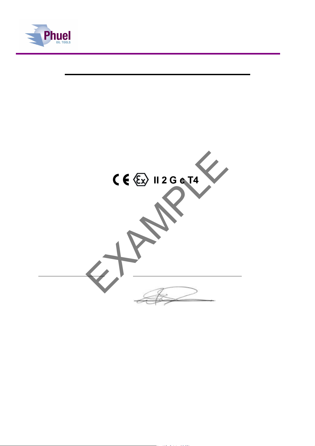
1Declaration of Conformity .........................................................................................................3
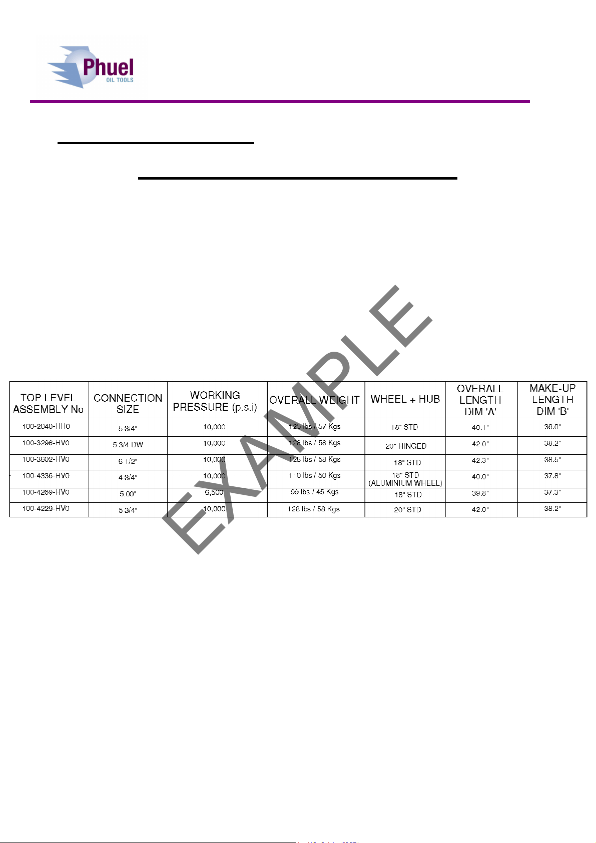
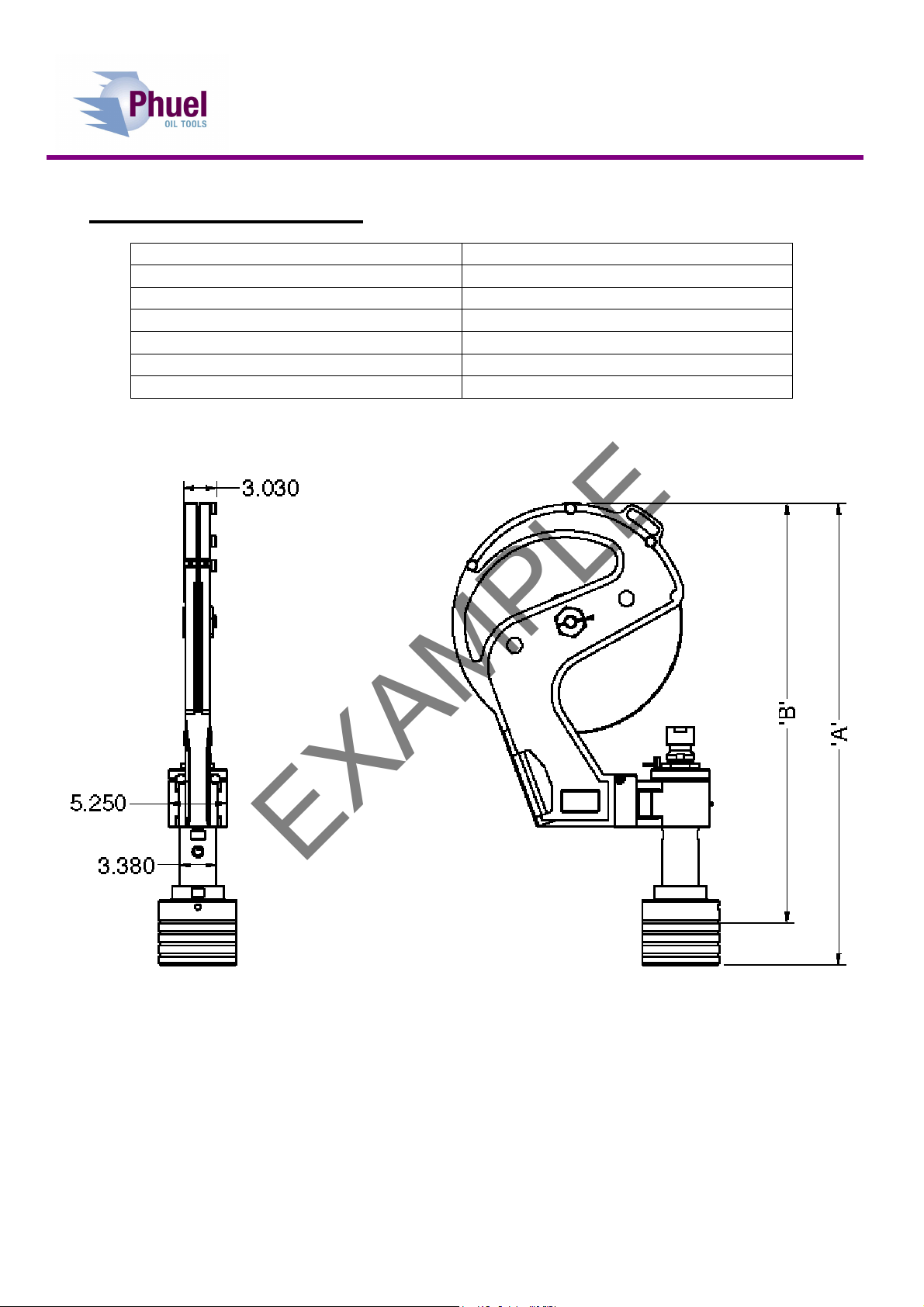
2Technical Specification .............................................................................................................5
3Parts List and Assembly Drawings ...........................................................................................6
4Spares ....................................................................................................................................12
4.1 Redress Kit ............................................................................................................. 12
4.2 Wire Specific Parts.................................................................................................. 12
4.3 Operation Specific Parts ......................................................................................... 13
4.4 Support Equipment ................................................................................................. 13
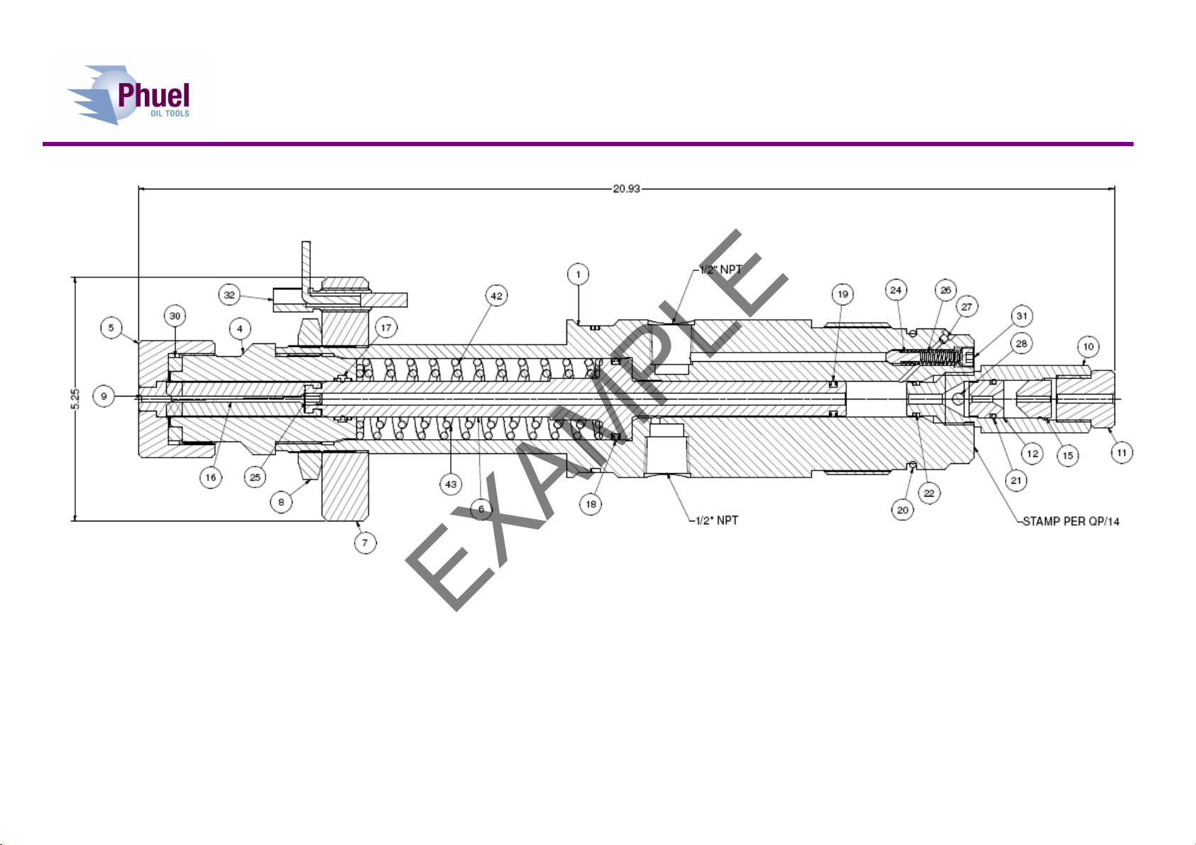
Table 1: Technical Data ...................................................................................................................5
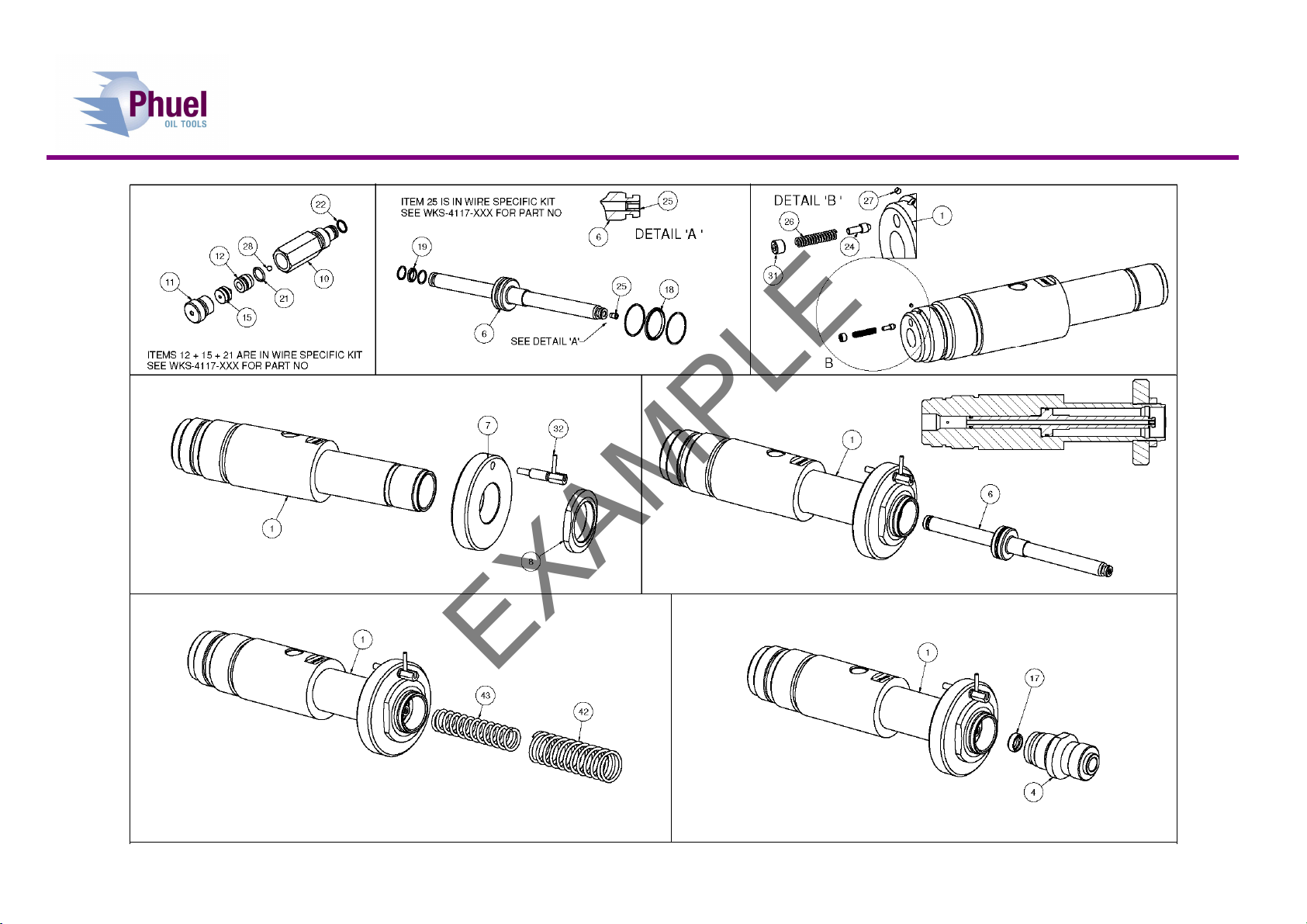
Table 2: Parts list 100-4336-HV0.....................................................................................................6
Table 3: 100-4252-HV0 Parts List....................................................................................................6
Table 4: 100-4253-HV4 Parts List..................................................................................................10
Table 5: 100-4250-HV0 Parts List..................................................................................................11
Table 6: Redress Kit Part No RDK-4336-HV0................................................................................12
Table 7: Redress Kit Part No RDK-4252-HV0................................................................................12
Table 8: Wire Kit WKS-4117-092 ...................................................................................................12
Table 9: Wire Kit WKS-4117-108 ...................................................................................................12
Table 10: Wire Kit WKS-4117-125.................................................................................................13
Table 11: Wire Kit WKS-4117-160.................................................................................................13
Table 12: Spacer Selection............................................................................................................13
Table 13: Support Equipment ........................................................................................................13
Figure 1: Dimensional Data..............................................................................................................5
Figure 2: 100-4252-HV0 ..................................................................................................................7
Figure 3: Assembly Procedure.........................................................................................................9
Figure 4: 100-4253-HV4 ................................................................................................................10
Figure 5: 100-4250-HV0 ................................................................................................................11
EXAMPLE

Technical Documentation
Stuffing Box
IPC-4336 Rev C 2
Revision History
Issue, Release Date Description
Rev A, 12 Jun 12 Initial Issue
Rev B, 11 Jul. 12 Item No’s Parts List Update
Rev C, 31 Oct 12 Removed spacer from line kits
EXAMPLE

Technical Documentation
Stuffing Box
IPC-4336 Rev C 3
1 Declaration of Conformity
DECLARATION OF CONFORMITY
Phuel Oil Tools Limited hereby declare that the following equipment
Slickline Stuffing Box
Model 100-2040-HH0
Model 100-3296-HV0
Model 100-3602-HV0
Model 100-4229-HV0
Model 100-4269-HV0
Model 100-4336-HV0
Also described as;
A mechanical device used for guiding Slicklines (Wire-lines) into well bores while containing well bore pressure
(excluded from the Pressure Equipment Directive by virtue of Annex ‘A’ 6 and 9) and is manufactured to achieve the
following specification.
Was found to be in accordance with;
The European Machinery Directive 98/37/EC being implemented in the United Kingdom by the Supply of
Machinery (Safety) Regulations 1992 and as amended by S.I. 1992/3073, S.I 1994/2063 and SI 2005/831
And the;
The European Directive on Equipment and Protective Systems Intended for Use in Potentially Explosive Atmospheres
94/9/EC, being implemented in the United Kingdom by The Equipment and Protective Systems Intended for Use in
Potentially Explosive Atmospheres Regulations 1996 (SI 1996/192) and as amended by The Equipment and
Protective Systems Intended for Use in Potentially Explosive Atmospheres (Amendment) Regulations 2001 (SI 2001
No.3766).
EXAMPLE

Technical Documentation
Stuffing Box
IPC-4336 Rev C 4
DECLARATION OF CONFORMITY
This equipment was designed to meet with the following European Harmonised Standards;
BS EN ISO 12100 Part 1 Safety of Machinery. Basic concepts, general principles for design
BS EN ISO 12100 Part 2 Safety of Machinery. Technical principles
BS EN 13463 Part 1: Non-electrical Equipment Intended for Use in Potentially Explosive Atmospheres - Basic Method
and Requirements.
BS EN 13463 Part 5: Non-electrical equipment intended for use in potentially explosive atmospheres - Protection by
constructional safety c.
BS EN 982 Safety of Machinery – Safety Requirements for Fluid Power Systems and Their Components - Hydraulics
BS EN 1050 Safety of Machinery – Principles for Risk Assessment
This equipment has been classified as suitable for use within a potentially explosive atmosphere as follows.
In addition to compliance with the aforementioned European Standards this equipment meets the requirements of the
following internationally recognised standards;
API 6A
I hereby declare that the equipment described in this document has been designed and manufactured in compliance
with the relevant sections and essential health and safety requirements of the aforementioned Standards, Codes and
Directives / Regulations.
Name Colin McKracken Position Managing Director
Signed: ________________
05 April 2012
EXAMPLE

Technical Documentation
Stuffing Box
IPC-4336 Rev C 5
2 Technical Specification
Part Number 100-4336-HV0
Connection 4 ¾’’
Maximum Working Pressure 10,000 Psi (689 Bar)
Test Pressure 15,000 Psi (1034 Bar)
Weight 110 lbs / 50 Kg
Overall Length (A) 40.0’’
Make Up Length (B) 37.8’’
Table 1: Technical Data
Figure 1: Dimensional Data
EXAMPLE

Technical Documentation
Stuffing Box
IPC-4336 Rev C 6
3 Parts List and Assembly Drawings
Item No
Part Number Description Quantity
1 100-4253-HV4
18" ALU SHEAVE WHEEL + STANDARD HUB 1
2 100-4252-HV0
PISTON PACKING HOUSING ASSEMBLY 1
3 100-4250-HV0
4 3/4"-4 (10K) SEAL SUB AND COLLAR ASSEMBLY
1
Table 2: Parts list 100-4336-HV0
Item No
Part Number Description Quantity
1 100-1974-480 HOUSING 1
4 100-1975-480 PACKING HOUSING 1
5 100-2033-480 TOP CAP 1
6 100-1977-B21 PISTON 1
7 100-1981-316 LOCK RING 1
8 100-1986-316 LOCKNUT 1
10 100-1979-B21 CHECK NUT 1
11 100-1988-B21 BOP RETAINER 1
17 802-1997-H80 ROD T-SEAL (.754 DIA) 1
18 802-1998-H80 PISTON T-SEAL (1.750 DIA) 1
19 802-1999-H80 PISTON T-SEAL (.750 DIA) 1
20 801-0232-V90 O-Ring - B.S Size 232 1
22 801-0113-V90 O-Ring - B.S Size 113 1
24 100-2114-PEK CHECK VALVE SEAL 1
26 100-2212-STL COMP SPRING (C5511230) 1
27 100-2005-STL LEE PLUG PLGA1560020A 1
28 100-2211-316 BALL BEARING 0.250 DIA 1
30 100-5058-### Select correct spacer for desired performance 1
31 100-2209-316 NPT SOCKET HEAD PLUG 1/8 1
32 100-1943-304 SPRING PLUNGER L HANDLE LOCKING 1
42 100-2692-STL OUTER SPRING 1
43 100-2693-STL INNER SPRING (RIGHT HAND) 1
999 WKS-4117-###
REPLACE WITH CORRECT WIRE SPECIFIC KIT
1
Table 3: 100-4252-HV0 Parts List
### refer to spares list for wire specific kits
EXAMPLE

Technical Documentation
Stuffing Box
IPC-4336 Rev C 7
Figure 2: 100-4252-HV0
EXAMPLE

Technical Documentation
Stuffing Box
IPC-4336 Rev C 8
EXAMPLE

Technical Documentation
Stuffing Box
IPC-4336 Rev C 9
Figure 3: Assembly Procedure
EXAMPLE

Technical Documentation
Stuffing Box
IPC-4336 Rev C 10
Item No
Part Number Description Quantity
13 100-2037-ALU BEARING HUB 1
14 100-2094-N66 DUST SEAL 2
29 100-2039-STL TAPERED ROLLER BEARING (32012XA) 2
33 100-2074-A69 SHEAVE BRACKET 18" 1
34 100-2204-ALU 18" SHEAVE WHEEL 1
35 100-2205-316 BEARING SHAFT 1
36 100-2206-316 BEARING NUT 1
37 100-2207-STL ROLLER BEARING (NUP308-E-TVP2) 1
38 100-2208-304 SPRING PLUNGER 3
39 145-2215-304 SPLIT COTTER PIN 1/8 X 3 LONG 1
40 100-2179-STL GREASE NIPPLE 1/8 NPT 2
41 801-0155-N70 O-Ring - B.S Size 155 2
44 SDU-0503-HTS
Set Screw Dog Point Size 1/4 Length 0.5 in
3
45 SCU-0587-3A4 Set Screw Cup Point 1/2 UNC x 1.25 Long 2
Table 4: 100-4253-HV4 Parts List
Figure 4: 100-4253-HV4
EXAMPLE

Technical Documentation
Stuffing Box
IPC-4336 Rev C 11
Item No
Part Number Description Quantity
2 100-4214-480 SEAL SUB 4.75-4 B 10K 1
3 100-4215-480 SOLID COLLAR 4.75-4 B 10K 1
23 801-0340-V90
O-Ring - B.S Size 340 1
99 910-4088-N66
4.750-4 ACME MALE THREAD PROTECTOR
1
Table 5: 100-4250-HV0 Parts List
Figure 5: 100-4250-HV0
EXAMPLE

Technical Documentation
Stuffing Box
IPC-4336 Rev C 12
4 Spares
Use only spares supplied or approved by Phuel Oil Tools Ltd.
It is recommended that sufficient quantities of the following spares be maintained to ensure that
the equipment is always available when required.
Elastomeric spares are supplied in Viton material as standard. Many other materials are available
please specify when ordering.
4.1 Redress Kit
Part Number Description Quantity
RDK-4252-HV0
REDRESS KIT FOR PISTON HOUSING ASSEMBLY
1
801-0155-N70
O-Ring - B.S Size 155 2
801-0340-V90
O-Ring - B.S Size 340 1
Table 6: Redress Kit Part No RDK-4336-HV0
Part Number
Description Quantity
802-1997-H80
ROD T-SEAL (.754 DIA) 1
802-1998-H80
PISTON T-SEAL (1.750 DIA)
1
802-1999-H80
PISTON T-SEAL (.750 DIA)
1
801-0232-V90
O-Ring - B.S Size 232 1
801-0114-V90
O-Ring - B.S Size 114 1
801-0113-V90
O-Ring - B.S Size 113 1
Table 7: Redress Kit Part No RDK-4252-HV0
4.2 Wire Specific Parts
Item No
Part Number Description Quantity
9 100-3425-092 WIRE BUSH 1
12 100-3427-092 BOP SEAT 1
15 100-3428-092 BLOW OUT PLUG 1
16 100-2514-PU8
S-BOX PACKING STICK-SET
2
21 801-0114-V90 O-R ng - B.S S ze 114 1
25 100-3426-092 PISTON PLUG 1
Table 8: Wire Kit WKS-4117-092
Item No
Part Number Description Quantity
9 100-3425-108 WIRE BUSH 1
12 100-3427-108 BOP SEAT 1
15 100-3428-108 BLOW OUT PLUG 1
16 100-2514-PU8
S-BOX PACKING STICK-SET
2
21 801-0114-V90 O-R ng - B.S S ze 114 1
25 100-3426-108 PISTON PLUG 1
Table 9: Wire Kit WKS-4117-108
EXAMPLE

Technical Documentation
Stuffing Box
IPC-4336 Rev C 13
Item No
Part Number Description Quantity
9 100-2526-B21 WIRE BUSH 1
12 100-1980-B21 BOP SEAT 1
15 100-1985-PU9
BLOW OUT PLUG 1
16 100-2514-PU8
S-BOX PACKING STICK-SET
2
21 801-0114-V90 O-R ng - B.S S ze 114 1
25 100-2527-B21 PISTON PLUG 1
Table 10: Wire Kit WKS-4117-125
Item No
Part Number Description Quantity
9 100-3425-B21 WIRE BUSH 1
12 100-3427-B21 BOP SEAT 1
15 100-3428-PU9
BLOW OUT PLUG 1
16 100-3476-PU8
S-BOX PACKING STICK (0.160)
2
21 801-0114-V90 O-R ng - B.S S ze 114 1
25 100-3426-B21 0.160 PISTON PLUG 1
Table 11: Wire Kit WKS-4117-160
4.3 Operation Specific Parts
The packing stick performance can be controlled by using the correct spacer for the intended
operational requirements. It is normally recommended that a low friction spacer should be selected
to avoid excessive friction on the wire. If there is sufficient tool weight or there is a desire to have a
full operating seal in the S-Box against the wire without any applied piston pressure then a high
pressure spacer should be used. Ensure that the specified spacer is fitted according to the line
being used.
Wire Size & Type Part No Thickness
0.125 – Low Fr ct on 100-5058-L25 0.400”
0.125 – H gh Pressure 100-5058-H25 0.330”
0.108 – Low Fr ct on 100-5058-L08 0.360”
0.108 – H gh Pressure 100-5058-H08 0.310”
0.092 – Low Fr ct on 100-5058-L92 0.330
0.092 – H gh Pressure 100-5058-H92 0.290
Table 12: Spacer Selection
4.4 Support Equipment
The following support equipment is available on order from Phuel Oil Tools
Part No Qty
Description
900-2042-STL
1 Test Blank
Table 13: Support Equipment
EXAMPLE
Table of contents
Other Phuel Industrial Equipment manuals