Piaa RF6 User manual

-1-
PKI-0041-5-E
RF6 / RF10 / RF18
InstallationInstructions
Pleasereadthecautionarypointsbeforeinstallationtoensuresafeutilizationoftheproduct.
●Thelampandtheswitchharnessareintendedformotorizedvehicleuseonly.Donotuseforanyotherpurpose.
●Thislampisintendedforuseinrain(dayornight),duringfoggyorsnowyconditionswherevisibilityishampered.
Donotuseduringnormaldrivingconditions.
●Donotoperatetheswitchwhiledriving,unlesslocallawsallowyoutodoso.
●Ifthelampiskeptonwhentheengineisnotrunning,itwilldrainthebattery.
●Makesurethelampisinstalledsecurelybeforedrivingthevehicle.Ifaproblemisfound,fixitimmediately.
●Checkforanyloosescrewsthatholdthelampinplacebeforedriving.Ifyoufindanyloosescrewsorbolts(ifabracketis
used),tightenthemsecurely.Ifyounoticealoosepartwhiledriving,inspectthesectionimmediatelyandmakethenecessary
adjustments.
●AvoidrepeatedlyturningthelampoffandonasitmayreducetheoveralllifeoftheLED.
●Somevehiclesproduceahighvoltageelectricchargewhentheengineisstarted.Avoidloadingextravoltagetolampsby
turningtheswitchoffwhenyoustartengine.
● Avoidneedlessdisassemblyofthelamportheswitchharnessasitmaycauseittofail.
●Ifthelampand/ortheswitchharnessisremovedandsetasideforsafekeeping,wipeawayalldustorgrimeandstoreina
placefreeofmoisture.
●Ifthelensiscrackedordamagedinanyway,verifywhetherthereisanydamagetotheharness.Ifthereisanydamageto
thecordcovering,replaceitimmediately.
●AvoidinjurywhenreplacingtheharnessandtheswitchPleasedisposeofitasanon-combustibleitem.
※ The and marksindicatedinthismanualare
cautionarypointsrelatedtotheinstallationoftheproduct.
Toensuresafeandsecureinstallationoftheproduct,pleasefollowthesepointsclosely.
Touser … Pleasekeepthismanualandareceiptwiththenameoftheshop
whereyouboughtit.
Whengivingthisproducttoathirdparty,alwaysincludethismanual
togetherwiththeproduct.
Toshopownersinstallingtheproduct … Afterinstallationoftheproduct,makesurethecustomerisprovided
withthisowner
'
smanual.
●Thelampbecomesveryhotwhenturnedon.Whenparkingyourcarnearflammableitemssuchasdriedleaves,turnoffthe
lampasitmaycauseafire.
●Donotlookdirectlyintothelightforlongperiods.Doingsomaycauseeyeirritationorvisualimpairment.
Thank you very much for purchasing PIAA product. Please read this instruction
manual thoroughly for proper use of the product. After completing your
installation, keep this manual for future reference.

-2-
PKI-0041-5-E
Pleasereadtheinstallationproceduresthoroughlybeforehand.
●Inorderforthelamptoperformatitsfullpotential,usetherelayharnessesmanufacturedbyPIAA.
●Allworkproceduresshouldbecarriedoutinalocationwithadequatespace.Placetheshiftleverintheparkingposition.
Turnofftheengineandsettheparkingbrake.
●Makesuretheenginecompartmentisadequatelycoolbeforestartingwork.Donotbeginworkifenginepartssuchasradiator,
oil-coolerorturbopartsarestillhot.
●Donotaddadditionalholestothemainbodyofthelamp.Also,donotapplyadhesivesorstickerstothelampparts.
●Donotmodifythelampharnessortheswitchharnessinanyway.Suchmodificationsmaycauseittooverheatorshort.Insome
cases,itmaycausethevehicletocatchfire.PIAAwillnotbeliablefordamagecausedbysuchmodifications.
●Whenremovingthebatteryterminals,donottouchthe(-)and(+)terminalssimultaneously.Anelectricalshockmayoccur.
Wearrubbergloveswhencarryingoutsuchworkprocedures.
●Makesurethe(-)and(+)terminalsdonotmakecontactwithmetal.Itcanbeextremelydangerousifashortoccurs.
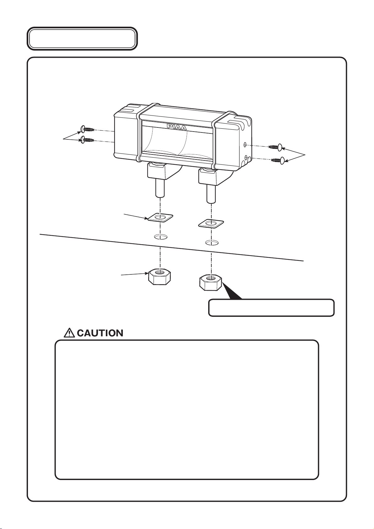
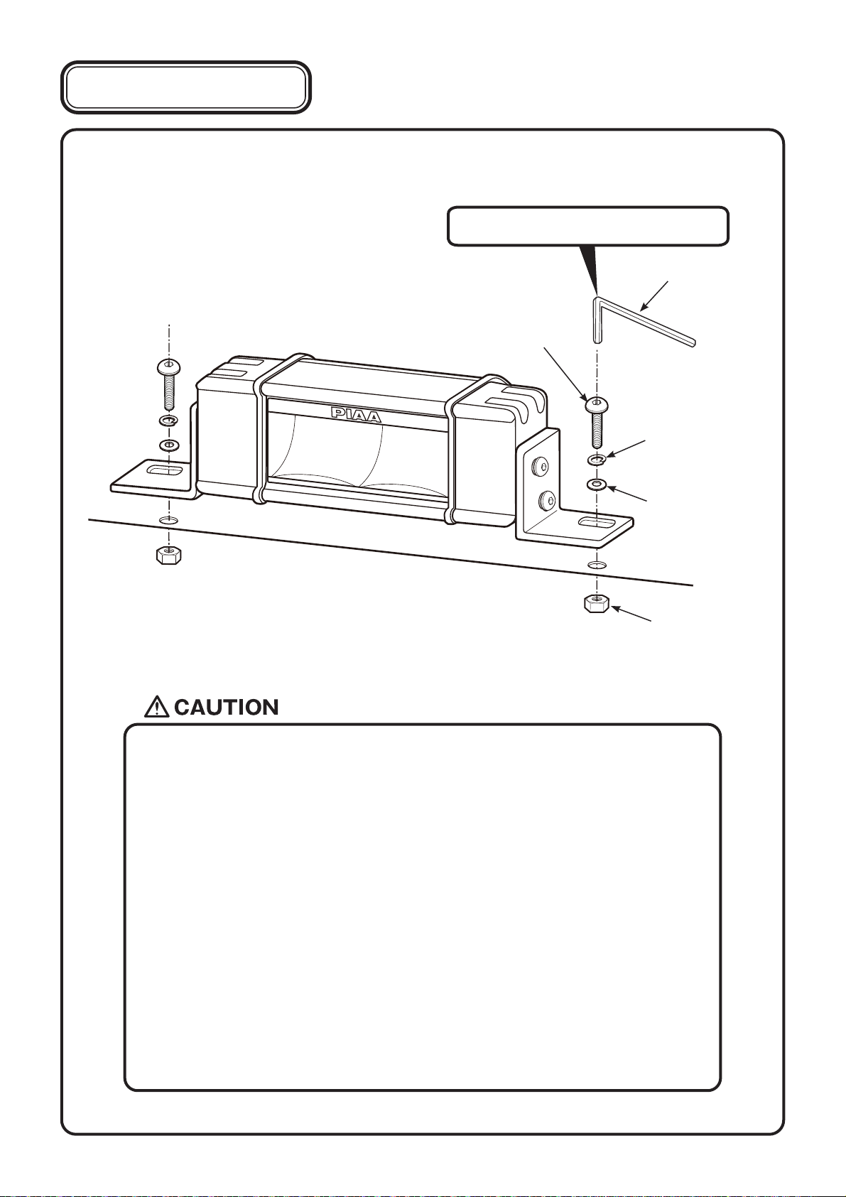
●Makesureallboltsaretightlysecure.Ifthereareanylooseboltstightenthemaccordingly.
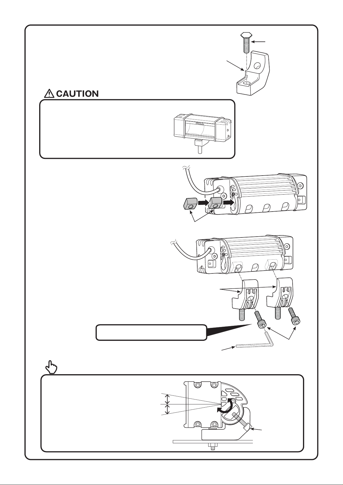
●Afterinstallingthelamp,adjustthelampsothebeamshinesatleast40minfrontofthevehicle.Also,adjustthelampalittle
towardtherightsothatitdoesnotshinedirectlyintotheeyesoftheopposingdriverofavehicle.(astrafficlawsstipulate-
refertop.6foradjustmentprocedures)
●Afterinstallingthelamp,makesuretheheadlamps,wipersandhornareworkingnormally.
●Whenthebatteryterminalisremoved,memoryrelatedtotheclock,radio,audiosystemetc,willbeaffected.Afterallwork
proceduresarecompleted,resettotheoriginalsettings.(Foradjustmentproceduresrefertoyourcar
'
sinstructionmanual)
●Wheninstallingthewiringharness,strictlyfollowthecautionarypointsmentionedbelow.Incorrectorfaultywiringmaycause
thelamptooperateincorrectly.Insomecases,itmaycausethevehicletocatchfire.
●Beforeyoubeginalwaysremovethe(-)and(+)terminals.
Alwaysremovethe(-)terminalfirstandmakesureashortdoesnotoccur.
●Whenremovingthebatteryterminals,alwaysturnthekeytoOFFandremoveit.Turnallotherelectricalunitsoffsuchas
thelightswitch.
●Whenremovingthebatteryterminals,ifacord(foranelectricalunit)isconnected,windalengthofvinyltapearoundthe
(-)and(+)terminalstoclearlyidentifythem.
●Verifythe(+)terminal(white)andearth(black)beforeconnecting.
●Donotobtain(+)voltagefromthealternator.
●Obtainthe(+)currentnecessaryfortheswitchfromthe(+)currentusedforthelightswitch.
(Donotusethesamecurrentusedforacomputer,radiooraudiosystem)
●Installtheswitchharnessinapositionwhereitwillnotmakecontactwithhightemperaturesurfacessuchastheengine,
radiatororenginecompartment.
●Arrangetheswitchharnesssothatitdoesnotmakecontactwithmovingparts.
●Donotplacetheswitchharnessonhigh-voltagewiressuchasbrakeorair-conditioningwires.
●Iftheswitchharnessmakescontactwithapartoftheengine,applyalengthofordinarycushionedtapearoundtheharness.
●Whenconnectingtheconnector,insertuntilyouhearanaudibleclick
●Whenremovingtheconnector,holdthemainbodyoftheconnectorandpullitout.Ifexcessforceisusedtopullthecord,it
maydamagetheconnection,whichcouldcauseittooverheat.
●Makesuretheharnessdoesnotsag.Useaharnessbandofvinyltapetosecureitinplacetowiringinsidetheenginecompartment.
●Beforeconnectingittothebattery,verifythewiringarrangement.
●Whenconnectingthebatteryterminalandorotherelectricalunits,donotmistakethe(-)and(+)terminals.Alwaysstartwith
the(+)terminal.
●Afterallwiringiscomplete,confirmthatitworksproperly.Ifitfailstoactivate,referto【8】Troubleshootingsectionofthis
manual.
CautionRegardingWiring/Pleasereadthoroughly

-3-
PKI-0041-5-E
※ Verifyallthepartsareincluded.Ifapartismissing,pleasecontactyourlocaldistributor.
※Dependingonmountingmethods,somepartsmaynotbeused.
ProductDetails
①Lampmainunit(1unit)
②Installation
bracketA(2pcs)
⑥Hexagonsocketheadbolt
(M10)(2pcs)
⑤ Rubbercushion
(2pcs)
③Hexagonheadbolt
(2pcs)
④Hexnut(L / M10)
(2pcs)
⑱Hexnut
(L / M8)(2pcs)
⑧Hexnut(S / M10)
(2pcs)
⑨Sidecap(4pcs)⑦Slider (2pcs)
Thisproductpackagecontains
onethefollowinglampunittypes
"RF6","RF10"or"RF18"
RF6
RF10
RF18
⑩Installation
bracketB(L)(1pc)
⑪Installation
bracketB(R)(1pc)
⑬Washer
(S / M6)(8pcs)
⑭ Springwasher
(S / M6)(4pcs)
⑫Hexagonsockethead
buttonbolt(S / M6)
(4pcs)
⑮Hexagonsockethead
buttonbolt(L / M8)
(2pcs)
⑯Washer
(L / M8)(2pcs)
⑰Springwasher
(L / M8)(2pcs)
MountingmethodA MountingmethodB
PartstobeusedinMountingmethodA.
PartstobeusedinMountingmethodB.

-4-
PKI-0041-5-E
㉔One-touch
connector(1pc)
㉕Wiretie
(5pcs)
㉚Hexagonalwrench
(M6)(1pc)
㉙Hexagonalwrench
(M8)(1pc)
㉘Hexagonalwrench
(M10)(1pc)
㉛Hexagonalwrench
(M4)(1pc)
⑲Connectionbracket
(1pc)
⑳Hexagonsocket
headbolt (M4)(2pcs)
※Pleaseusethetoolsindicatedbelow.
● Pliers
ToolsRequired
● 17mmwrench ● 13mmwrench
【1】Installationpreparations
×2
Hexnut
(S/Item ⑧ )
Slider(Item ⑦ )
(1)CombinetheSlider(Item⑦ )andtheHexnut(S/Item⑧ )
asshowninthefigurebelow.
MountingmethodA
●IfinstallwiththeMountingmethodA
onthevehicle,refertoP4〜 P8.
●IfinstallwiththeMountingmethodB
onthevehicle,refertoP9〜P12.
㉒Switch
(1pc)
㉖Rubbercap
(2pcs)
㉗Dummyconnector
(1pc)
㉑Pre-assembledrelayharness
withfuse【LR-39】(1set)
㉓Double-sticktape
forswitch (1pc)

-5-
PKI-0041-5-E
Hexagonheadbolt
(Item ③ )
InstallationbracketA
(Item ② )
(2)CombinetheInstallationbracket(Item② )andthe
Hexagonheadbolt(Item③ )asshowninthefigure
below.
(3)Take2setsmadeupoftheHexnutandSlider
assemblythatwascombinedin(1)puttheminto
thelampmainunitpositionsasindicatedinthe
figure.BecarefulnottodroptheHexboltoutof
theSlider.
●IfinstallingthelampmainunitsRF10and
RF18tothevehicleswithoutcombiningthem,
makesuretoinstall2Installationbracketson2
positionsonthelampmainunit.WithunitRF6,
oneInstallationbracketcanbeusedinthecenter
butwerecommendinstallingthemon2positions.
Sliderassembly
(4)Take2setsmadeupoftheHexnutandbracket
assemblythatwerecombinedin(2)andusingthe
Hexagonsocketheadbolt(M10/Item⑥ ),screwit
firmlyinplace.
Hexagonsocket
headbolt
(M10)(Item ⑥ )
Hexagonalwrench
(M10)(Item ㉘)
InstallationbracketA
(Item ② )
Tighteningtorque:18ft・Ibs(24N・m)
●Afterthelampsareinstalledonthe
vehicle,theHexagonsockethead
bolts(M10/Item⑥ )canbeloosed
andtheangleofthelampcanbe
adjusted.
Advice
10°
10°
Hexagonsocket
headbolt
(M10)(Item ⑥ )

-6-
PKI-0041-5-E
● Whenusingacommerciallysuppliedlampbracket,beforeremovingtheboltthatisalreadyinstalled
onthecarbody,makesurethatitissafetodoso.
● Thelampshouldbemountedinanareasufficienttosupportitssizeandweight.
Failuretodosomayresultinexcessivevibrationleadingtoshorterbulblifeandorphysicaldamage
tothelamporyourvehicle.
● Donotattempttoinstallthelampdirectlytoanyplasticpartofthecarbody.
● Wheninstalling,makesurethelampbody,lensandrimarenottouchingthebumperandotherplastic
parts.Suchplasticpartsmightdeform.
● Thelampinstallationsurfaceshouldbeflat.
● Thelampshouldbetightenedtothedegreethatthelampbodycannotbemovedbyhand.
● Thelampsaredesignedtobemountedupright.ItisveryimportantthatyoumakesurethatthePIAA
etchedinthelensreadsrightsideup.
Forlampinstallation,aholewithadiameterof
10mmisrequired.Makenecessarypreparation
suchasinstallationoflampbracket.
Hexnut
(L/Item ④ )
【2】Lampinstallation
Rubbercushion
(Item ⑤ )
Tighteningtorque:18ft・Ibs(24N・m)
Sidecap
(Item ⑨ )
Sidecap
(Item ⑨ )

-7-
PKI-0041-5-E
【3】Beforestartingtheworkprocedures...
ByusingtheConnectionbracket(Item ⑲ )2mainlampunits(Item ① )canbeconnected.
Wheninstallingandusingthemainlampunit,followthe■Lampconnectionproceduresindicatedbelow.
Ifnotinstallingthemainlampunitusingthisprocedurecontinueontopage4,【1】Installationpreparations
andfollowtheinstructionsindicatedthere.Inaddition,ifnotconnectingthelamps,theconnectionbrackets
(Item ⑲ )andtheHexagonsocketheadbolt(M4/Item ⑳ )willnotbeused.Therefore,pleasestorethem
properlyforsafekeeping.
InstalltheConnectionbracket(Item⑲ )tothenutonthelampmainunitasshowninthefigure.Usethe
Hexagonsocketheadbolt(M4/Item⑳ )tosecureitfirmlyinplace.
Lampmainunit(Item①)
Nutsections
Connectionbracket
(Item ⑲)
Hexagonsocket
headbolt(M4)
(Item⑳)
Hexagonalwrench(M4)
(Item ㉛)
Tighteningtorque:2.2ft・Ibs(3N・m)
※Thefollowingworkproceduresshownbelowareforthe
"RF6"modelbutthesameprocedurescanalsobeused
forunits"RF10"and"RF18".
■Lampconnectionprocedures

-8-
PKI-0041-5-E
●UsetherecommendedtorqueandapplyequalforcewhentighteningtheHexagonsocketheadbolt
(M4/Item⑳ ).
●Ifconnecting3lampsinarow,makesuretoinstalltherightnumberofbracket(s)foreachsizefalamp.
●WhenconnectinglampunitsRF6andRF10,werecommendthat2InstallationbracketsA(Item② )
beusedoneachlampunit.
IfthereisaproblemwiththeinstallationpositionandonlyoneInstallationbracketAcanbeinstalledon
eachlamp,installitontheouterholefromcenter.
●WheninstallingandusingRF18unit,makesuretoinstall2InstallationbracketsA(Item② )at
2positionsoneachlamp.
Afterinstallingthelamp,followtheP13 【7】
RelayHarnessInstallationSequence.
InstallationbracketA
Center
Center
Center
Center Center
Center

-9-
PKI-0041-5-E
【4】Installationpreparations
CombinethelampandinstallbracketsBasshowninthefigurebelow.
Hexagonsocketheadbuttonbolt
(S/M6)(Item ⑫ )
●Afterthelampsareinstalledonthevehicle,theHexagonsocketheadbuttonbolts(S/M6)(Item⑫ )
canbeloosed andtheangleofthelampcanbeadjusted.
Advice
10°
Hexagonsocket
headbuttonbolt
(S/M6)(Item ⑫ )
InstallationbracketB(R)
(Item ⑪ )
Washer(S/M6)
(Item ⑬ )
InstallationbracketB(L)
(Item ⑩ )
InstallationbracketB
(Item⑩/⑪)
Springwasher
(S/M6)(Item ⑭ )
Hexagonal
wrench(M6)
(Item ㉚)
Tighteningtorque:6.6ft・Ibs(9N・m)
MountingMethodB

-10-
PKI-0041-5-E
Forlampinstallation,aholewithadiameterof
8mmisrequired.Makenecessarypreparation
suchasinstallationoflampbracket.
【5】Lampinstallation
● Whenusingacommerciallysuppliedlampbracket,beforeremovingtheboltthatisalreadyinstalled
onthecarbody,makesurethatitissafetodoso.
● Thelampshouldbemountedinanareasufficienttosupportitssizeandweight.
Failuretodosomayresultinexcessvibrationleadingtoshorterlifeandorphysicaldamageto
thelamporyourvehicle.
● Donotattempttoinstallthelampdirectlytoanyplasticpartofthecarbody.
Ifthelampneedstobeinstalledontheplasticreinforcementmaterialsshouldbeplacedonboth
sidesoftheplasticpart.
● Wheninstalling,makesurethelampbody,lensandrimarenottouchingthebumperandotherplastic
parts.Suchplasticpartsmightdeform.
● Thelampinstallationsurfaceshouldbeflat.
● Thelampshouldbetightenedtothedegreethatthelampbodycannotbemovedbyhand.
● Thelampsaredesignedtobemountedupright.ItisveryimportantthatyoumakesurethatthePIAA
etchedinthelensreadsrightsideup.
Hexnut
(L/M8)(Item ⑱ )
Tighteningtorque:11ft・Ibs(15N・m)
Hexagonsocket
headbuttonbolt
(L/M8)(Item ⑮ )
Washer(L/M8)
(Item ⑯ )
Springwasher
(L/M8)(Item ⑰ )
Hexagonal
wrench(M8)
(Item ㉙)

-11-
PKI-0041-5-E
【6】Beforestartingtheworkprocedures... ※Thefollowingworkproceduresshownbelowareforthe
"RF6"modelbutthesameprocedurescanalsobeused
forunits"RF10"and"RF18".
ByusingtheConnectionbracket(Item ⑲ )2mainlampunits(Item ① )canbeconnected.
Wheninstallingandusingthemainlampunit,followthe■Lampconnectionproceduresindicatedbelow.
Ifnotinstallingthemainlampunitusingthisprocedurecontinueontopage9,[4]Installationpreparations
andfollowtheinstructionsindicatedthere.Inaddition,ifnotconnectingthelamps,theConnectionbrackets
(Item ⑲ )andtheHexagonsocketheadbolt(M4/Item⑳ )willnotbeused.Therefore,pleasestorethem
properlyforsafekeeping.
InstalltheConnectionbracket(Item⑲ )tothenutonthelampmainunitasshowninthefigure.Usethe
Hexagonsocketheadbolt(M4/Item⑳ )tosecureitfirmlyinplace.
Lampmainunit(Item①)
Nutsections
Connectionbracket
(Item ⑲)
Hexagonsocket
headbolt(M4)
(Item⑳)
Hexagonalwrench(M4)
(Item ㉛)
Tighteningtorque:2.2ft・Ibs(3N・m)
■Lampconnectionprocedures

-12-
PKI-0041-5-E
●UsetherecommendedtorqueandapplyequalforcewhentighteningtheHexagonsocketheadbolt
(M4/Item⑳ ).
●Donotconnectmorethan2lampmainunits.
●Donotconnect2unitsof
"RF18"togetherusingMountingmethodB.

-13-
PKI-0041-5-E
Thenumbersshowninthefigurebelowindicatethesequencethepartsshouldbeinstalled.
【7】RelayHarnessInstallationSequence
Removethe(-)terminalfromthe
battery.
Removethe(+)terminalfromthe
battery.
Bringtherelayconnectorintothe
interiorofthevehicleandconnect
totheswitch’sconnector.
Takethe(+)cord(white)andusingthe
one-touchconnector,tieittogethertothe
vehicle’s(+)cord.
Ifonly1lampwillbeinstalled,sealtheunusedconnector
withtheRubbercapandDummyconnectorincludedinkit.
Connectthelampharness
totheconnector.
Firstgroundtheterminal
thentakethe(-)cord
(black)andconnectitto
the(-)terminal.
Takethe(+)terminal
cord(white)andattach
ittothe(+)terminaland
connecttothebattery.
Attachthe(-)
terminaltothe
battery.
Afterlamphasbeeninstalled,verifytherelay
harnessdoesnotmakecontactwiththe
engine’smovingpartsorsectionsthatemit
extremeheat.Usethewiretieincludedand
securetoharnessesinsideenginecompartment.
Harness
Wiretie
※ Useapairofplierstoverifytheone-touch
connectorissecure.
Switch
Relay
Battery
Cord
One-touch
connector
(+)cord(white)
(-)cord(Black)
Makesuretoproperly
securetherelayunit
usingboltsoraharness.
Theharnessmustalso
befacingdownward.
Double-sticktapeforswitch.
Placeinareathatiseasily
accessiblefromdriver’sseat.
Facingdown
(+)cord(white)
Rubbercap Dummy
connector

-14-
PKI-0041-5-E
1 Afterinstallation,ifthelampdoesnotactivate
→ Checkthewiringandmakesuretherearenofaultyorirregularconnections.
●Iftheswitchilluminationdoesnotlightup.
→ Verifythe(+)wirefromtheswitchisproperlyconnected.Ifitisnotcorrectlyconnecteditwillnotactivate.
→ Verifythefuselocatedonthevehicle
'
swiringsystem.(theswitch
'
s(+)wireshouldbeconnectedtothe
fusebox).Ifitisburnedout,connectittoanothercircuit.
→ Iftheswitchitselfisfaulty,thesamesymptomsmayexist.Werecommendthattheentireswitchunit
bereplaced.
→ Checkthefusefortheswitchharness.Ifitisburnedout,followinstructionsindicatedin
[3FusereplacementProcedures].
●Theswitchilluminationlightsupbutwhenoperatingdoesnotwork.
→ Checktheconnecting(-)cordtothebodyearth.
→ Theremaybecaseswhereeachterminalrelatedtospecificsectionsmaybeincorrectlyconnected.
Checkforanylosewiresandalsofordirtorgrime.
→ ChecktheswitchoperationIfanabnormalityisfound,replaceitaccordingly.
2 IftheLEDsuddenlyfailstolightup…
→ Checkthefuselocatedonthevehicle
'
swiringsystem.Ifitisburnedout,replaceaccordingly.
→ Checkthefusefortheswitchharness.Ifitisburnedout,followinstructionsindicatedin
[3FusereplacementProcedures].
→ Theremaybecaseswhereeachterminalrelatedtospecificsectionsmaybeincorrectlyconnected.
Checkforanylosewiresandalsofordirtorgrime.
→ Checktheswitchoperationifanabnormalityisfound,replaceitaccordingly.
3 Fusereplacementprocedures
→ Ashortcircuitmayhaveoccurred.Checkthewiringsystem.Ifanytypeofdamageis
foundreplaceaccordingly.(Non-replacementmayposeapotentialdanger)(Shortcircuitsaremainly
causedwhenwiresarecaughtintheassemblyorwhenthereisagapinthesleeveconnectedtothe
lampharness).
【8】Troubleshooting……
Verifyeachsectionaccordingtothefollowing.
Typically,drivinglightsaremountedabovethefrontbumperabout30inchesfromthegroundtoprovideextrahigh
beamillumination.Drivinglightscanbemountedbelowthebumper,althoughtheywillnotbeaseffectivebecause
thelightwillhitthegroundsoonerandreducetherangeofthelight.
Visualaimismadewiththecenterofthebeamhotspot1.5inchesbelowthelampcenterat25feetwiththelamp
facingstraightforward.(seebelow.)
● Donotusedrivinglightsinto
oncomingtraffic.
Drivinglightsshouldneverbe
theonlyforwardlightsource.
Drivinglightsshouldonlybe
usedwiththeheadlamphigh
beams.
1.5
DRIVING / SpotLightAiming

-15-
PKI-0041-5-E
【9】PIAALIMITEDWARRANTY
Withtheexceptionofbulbs,PIAACorporation,USA("PIAA")warrantsitsproductstobefreefrom
defectsinworkmanshipandmaterialsundernormaluseforaslongastheoriginalpurchaserownsthem.
EXCLUSIONS
ThisLimitedWarrantyspecificallyexcludesdefectsresultingfrommisuse,abuse,neglect,alteration,
modification,improperinstallation,unauthorizedrepairs,submersion,theft,vehiclecrash,orbyany
othertypeofimpact.ExceptfortheLimitedWarrantystatedabove,therearenowarrantiesofPIAA
productsoranypartthereof,whetherexpressorimplied.Anyimpliedwarrantyofmerchantability
oranywarrantyoffitnessforaparticularpurposeisexpresslydisclaimed.Somestatesdonot
permitthedisclaimerofimpliedwarranties.
LENSCRACKS
Crashorimpactdamageisnotcovered.Thiscanbedeterminedbyachiporscrapeonthelensorthe
housing.Stresscrackssometimesoccurwhenthelensissubjectedtosuddenandextremetemperature
changes.Astresscrackhasnochiporothersignofimpact.Stresscracksarecoveredunderwarranty.
EXCLUSIONOFDAMAGES
InnoeventshallPIAAbeliableforanydamageswhatsoever(including,withoutlimitation,consequential
damages,incidentaldamages,ordamagesforlossofuse,lossofbusinessprofits,businessinterruption,
lossofbusinessinformation,lossoftime,inconvenience,orotherlosses)arisingoutoftheuse,misuse,
orinabilitytouseaPIAAproduct.PIAAreservestherighttochangethedesignitsproductswithoutany
obligationtomodifyanypreviousproduct.Thiswarrantygivesyouspecificlegalrights.Youmayalso
haveotherrightsthatvaryfromstatetostate.
REPAIRANDREPLACEMENT
IfaPIAAproductissuspectedofbeingdefective,itmustbesubmittedfreightprepaid,toeitheran
authorizeddealerordistributorforwarrantyinspection.Thereceiptorotherproofofpurchaseanda
descriptionoftheproblemmustbeincluded.Thereturnedproductwillbeinspected.Iftheproductis
foundtobedefectiveandcoveredbythisLimitedWarranty,thesoleremedyisrepairorreplacement,at
PIAA'soption.Arepairedorreplacementproductwillbeshippedbackatnocharge,andwillbewarranted
tobefreefromdefectsinworkmanshipandmaterialsundernormaluseforaslongastheoriginal
purchaserownsit.Removal,installation,orreinstallationcostsarenotcoveredbythisLimitedWarranty.
PIAA CORPORATION
www.piaa.com
www.piaa.co.jp
This manual suits for next models
2
Table of contents
Other Piaa Lighting Equipment manuals
Popular Lighting Equipment manuals by other brands

Tamlite
Tamlite CYCLONE X Installation & operating instructions

Honeywell
Honeywell FF-LS14 Series installation manual

Philips
Philips BN131C LED SWT/SCCT L600 PSU Slim Mounting instruction

Wibre
Wibre Retrofit installation manual

RSA Lighting
RSA Lighting ACT955RM Specification sheet

Chroma
Chroma Color Force 12 user manual