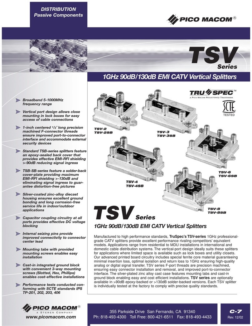
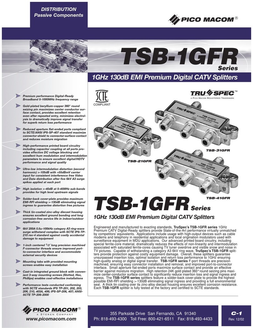
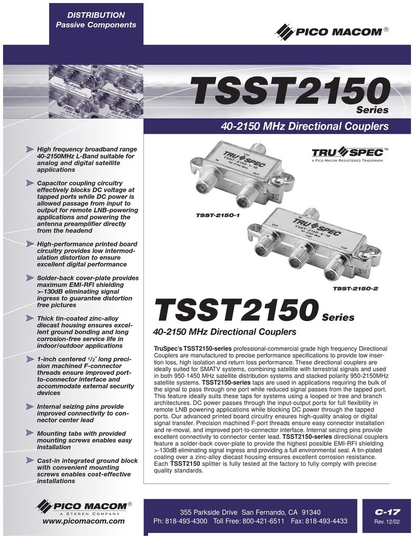
Pico Macom XUV User manual

PICO MACOM INC. 12500 Foothill Blvd. • Lakeview Terrace CA 91342 • (818) 897-0028 • (800) 421-6511 • FAX (818) 834-7197
Installation
And
Operation
Manual
PICO MACOM,INC.
XUV UHF TO VHF
CONVERTER
OM2090-1 Rev.A

PICO MACOM INC. 12500 Foothill Blvd. • Lakeview Terrace CA 91342 • (818) 897-0028 • (800) 421-6511 • FAX (818) 834-7197
S A F E G U A R D S
Product Inspection
Inspect the equipment for shipping damage.
Should any damage be discovered, immediately file
a claim with the carrier.
Important
Safety Instructions
To ensure proper installation and operation,
take a moment to read this guide before proceeding
with the installation. If you have any questions or
comments about the X V HF to VHF converter,
please contact your dealer or have him contact the
PICO MACOM Service Center at the phone num-
bers at the bottom of the page.
WARNING: TO REDUCE THE RISK OF FIRE OR ELECTRIC SHOCK DO NOT EXPOSE
THIS APPLIANCE TO RAIN OR MOISTURE. DO NOT OPEN THE CABINET REFER
SERVICING TO QUALIFIED PERSONNEL ONLY.
CAUTION: TO PREVENT ELECTRIC SHOCK DO NOT USE THIS (POLARIZED) PLUG
WITH AN EXTENSION CORD RECEPTACLE OR OTHER OUTLET UNLESS THE BLADES
CAN BE FULLY INSERTED TO PREVENT BLADE EXPOSURE.
ATTENTION: POUR PREVENIR LES CHOCS ELECTRIQUES NE PAS UTILISER CETTE
FICHE POLARISEE AVEC UN PROLONGATEUR UNE PRISE DE COURANT OU UNE
AUTRE SORTIE DE COURANT SAUF SI LES LAMES PEUVENT ETRE INSEREES A FOND
SANS EN LAISSER AUCUNE PARTIE A DECOUVERT.
1. Read Instructions - All the safety and operating instruction should be read
before the appliance is operated.
2. Retain Instructions - The safety AND operating instructions
should be retained for future reference.
3. Head Warnings - All warnings on the appliance should be
adhered to.
4. Follow Instructions - All operating and use instructions should
be followed.
5. Cleaning - nplug this appliance from the wall outlet before
cleaning. Do not use liquid cleaners or aerosol cleansers. se a damp
cloth for cleaning.
6. Do Not se Attachments - not recommended by the manufac-
turer or they may cause hazards.
7. Water and Moisture - Do not use this product near water - for
example, near a bathtub, washbowl, kitchen sink, laundry tub, in a wet
basement, or near a swimming pool - and the like.
8. Accessories - Do not place this product on an unstable cart, stand,
tripod, bracket, or table. The product may fall, causing serious injury
to a child or adult, and serious damage to the appliance.
9. Ventilation - This video product should never be placed near or
over a radiator or heat register. This video product should not be
placed in a built-in installation such as a bookcase or rack unless
proper ventilation is provided or the manufacturer’s instructions have
been adhered to. Any slots or opening in the
cabinet are provided for
v
entilation. To ensure reliable operation OF the video product and to
protect it from overheating, these openings must not be blocked or
covered. The openings should never by blocked by placing the
product on a bed, sofa, rug, or other similar surface.
The lightning flash with arrowhead sym-
bol within an equilateral triangle is in-
tended to alert the user to the presence of
uninsulated "dangerous voltage" within
the product's enclosure that may be of
sufficient magnitude to constitute a risk of
electric shock to persons.
The exclamation point within an equilat-
eral triangle is intended to alert the user to
the presence of important operating and
maintenance (servicing) instructions in the
literature accompanying the appliance.
IMPORTANT INFORMATION
1

PICO MACOM INC. 12500 Foothill Blvd. • Lakeview Terrace CA 91342 • (818) 897-0028 • (800) 421-6511 • FAX (818) 834-7197
10. Grounding or Polarization - This video product is equipped
with a polarized alternating - current line plug (a plug having one
blade wider than the other). This plug will fit into the power socket
only one way. This is a safety feature. If you are unable to insert the
plug full into the outlet, try reversing the plug. If the plug should still
fail to fit, contact your electrician to replace your obsolete outlet. Do
not defeat the safety purpose of the polarized plug.
11. Power Sources - This product should be operated only from the
type of power source indicated on the marking label. If you are not
sure of the type of power supplied to your home, consult your
appliance dealer or local power company.
12. Power-cord Protection - Power-supply cords should be routed
so they are not likely to be walked on a pinched by items placed upon
or against them. Pay particular attention to cords at plugs, conve-
nience receptacles, and the the point where they exit from the
appliance.
13. Lightning - For added protection for this product during a
lightning storm, or when it is left unattended and unused for long
periods of time, unplug it from the wall outlet.
14. Power Lines - An outside antenna system should not be located
in the vicinity of overhead power lines, other electric light or power
circuits, where it can fall into such power lines or circuits. When
installing an outside antenna system, extreme care should be taken to
keep from touching such power lines or circuits as contact with them
may be fatal.
15. Overloading - Do not overload wall outlets and extension cords
as this can result in risk of fire or electric shock.
16. Object and Liquid Entry - Never push objects of any kind into
this product through openings as they may touch dangerous voltage
points or short-out parts that could result in a fire or electric shock.
Never spill liquid of any kind on the product.
17. Servicing - So not attempt to service this product yourself as
opening or removing covers may expose you to dangerous voltage or
other hazards. Refer all servicing to qualified service personnel.
18. Damage Requiring Service - nplug this product from the wall
outlet and refer servicing to qualified service personnel under the
following conditions:
a. When the power-supply cord or plug is damaged.
b. If liquid has been spilled, or objects have fallen into the product.
c. If the product has been exposed to rain or water.
d. If the product does not operate normally by following the
operating instruction. Adjust only those controls that are covered by
the operating instructions. An improper adjustment may result in
damage and will often require extensive work by a qualified techni-
cian to restore the product to its normal operation.
e. If the product has been dropped or the cabinet has been damaged.
f. When the product exhibits a distinct change in performance - this
indicates a need for service.
STANDOFF
INSULATORS
b
MAST
ANTENNA
LEAD-IN WIRE
c
GROUND WIRE
TO EXTERNAL ANTENNA
TERMINALS OF PRODUCT
ANTENNA
DISCHARGE UNIT
GROUND CLAMPS
OPTIONAL ANTENNA GROUNDING ELECTRODE
DRIVEN 8 FEET (2.44M) INTO THE EARTH
IF REQUIRED BY LOCAL CODES. SEE NEC
SECTION 810 - 21(f).
BONDING JUMPERd
GROUND CLAMPS
POWER SERVICE GROUNDING
ELECTRODE SYSTEM
(e.g. interior metal water pipe)
SERVICE
ENTRANCE
EQUIPMENT
SERVICE ENTRANCE
CONDUCTORS GROUND CLAMP
POWER LINES
EXAMPLE OF ANTENNA GROUNDING ACCORDING TO
NATIONAL ELECTRICAL CODE INSTRUCTIONS CONTAINED
IN ARTICLE 810 - "RADIO AND TELEVISION
EQUIPMENT"
NOTE TO THE CATV SYSTEM INSTALLER:
THIS REMINDER IS PROVIDED TO CALL THE CATV SYSTEM
INSTALLER’S ATTENTION TO ARTICLE 820 - 22 OF THE NEC
THAT PROVIDES GUIDELINES FOR PROPER GROUNDING
AND,INPARTICULAR,SPECIFIESTHATTHECABLEGROUND
SHALL BE CONNECTED TO THE GROUNDING SYSTEM OF
THE BUILDING, AS CLOSE TO THE POINT OF CABLE ENTRY
AS PRACTICAL.
IMPORTANT INFORMATION CONT'D
S A F E G U A R D S
2
19. Replacement Parts - When replacement parts are required, be
sure the service technician has used replacement parts specified by the
manufacturer or have the same characteristics as the original parts.
nauthorized substitutes may result in fire, electric shock or other
hazards.
20. Safety Check - pon completion of any service or repairs to this
product, ask the service technician to perform safety checks to
determine that the product is in proper operating conditions.
21. Outdoor Antenna Grounding - Before attempting to install this
product, be sure the antenna or cable system is grounded so as to
provide some protection against voltage surges and built-up static
charges.
a. se No.10 AWG (5.3mm ) copper, No.8 AWG (8.4mm (alumi-
num, No.7 AWG (10mm ) copper-clad steel or bronze wire or larger,
as ground wire.
b. Secure antenna lead-in and ground wires to house with stand-off
insulators spaced from 4 feet (1.22m)
to 6 feet (1.83m) apart.
c. Mount antenna discharge unit as close as possible to where lead-
in enters house.
d. A driven rod may be used as the grounding electrode where
other types of electrode systems do not exist. Refer to the National
Electrical Code, ANSI/NFPA 70-1984 for information.
e. se jumper wire not smaller than No.6 AWG (13.3mm ) copper or
equivalent, when a separate antenna grounding electrode is used.


PICO MACOM INC. 12500 Foothill Blvd. • Lakeview Terrace CA 91342 • (818) 897-0028 • (800) 421-6511 • FAX (818) 834-7197
INTRODUCTION TO UHF CONVERSION
I N T R O & S P E C S
3
The X V commercial HF to VHF converter
relocates a single HF TV channel to a lower
frequency VHF TV channel. A crystal controlled
PLL oscillator is used to mix with the
amplifiedfiltered HF signal. The converted
signal is filtered and amplified once again at VHF.
A strip amplifier is frequently used after the
conversion to provide additional bandpass filtering
and to provide automatic gain control. Since the
signal is now at the same amplitude of the other
headend signals, the difficulty of distributing the
high frequency signal has been eliminated.
Bandpass Filtering The bandpass filtering
within the X V is sufficient to eliminate unwanted
HF channels and mixer products on all but a few
conversion combinations. The table on page 7
S P E C I F I C A T I O N S
Frequency Spectrum:
HF 14 -70 to Low band
HF 14 -70 to Mid band
HF 14 -70 to High band
Frequency Stability: + /- 5 kHz
Conforms to FCC Docket 21006
Minimum Input: -7 dBmv
Input Impedance: 75 ohms
Return Loss:
Input: 14 dB (on channel)
Output: 14 dB (on channel)
Gain: 20 dB
Maximum Output: 47 dBmv
Image Rejection: -40 dB
Input Noise Figure:
CH 14 to 35: 9 dB
CH 36 to 52: 10 dB
CH 53 to 77: 12 dB
Skirt Selectivity:
+/- 6 Channels: -60 dB
+/- 3 Channels: -40 dB
+/- 2 Channels: -20 dB
AURAL
TEST
MONITOR
CH- TO
120VA
60HZ 10W
600VA MAX
UHF IN VHF OUT +
+++
+
+
+
XUV
SINGLE CHANNEL CONVERTER
lists the conversions that produce spurious mixer
products requiring additional bandpass filtering.
nder some input conditions it is also
recommended to bandpass the output of the
converter prior to the strip amplifier. Additional
filtering is suggested when equal level signals
exist within 4 channels of the desired HF channel.
Also, input bandpass filtering may be necessary
when a very strong HF signal is located within 2
channels of the desired weak HF signal.
Input Levels: PICO MACOM recommends
that the input level to the X V be greater than 3
dBmv. Weaker signals will still be converted but
the signal to noise is best maintained above 3
dBmv. The mast mounted MPA-25 pre-amplifier
is recommended for weak signal conditions.

PICO MACOM INC. 12500 Foothill Blvd. • Lakeview Terrace CA 91342 • (818) 897-0028 • (800) 421-6511 • FAX (818) 834-7197
4
XUV FIELD CHANNEL CONVERSION
FIELD ALIGNMENT
CHANGING THE INP T CHANNEL
1. Verify operation of existing X V/PLL by
inserting the input signal and monitoring the
output on TV set and field strength meter.
2. Check the Channel Conversion Table to verify
that the new combination of input and output
channels is an acceptable conversion. Also,
determine the new oscillator frequency.
3. sing the PLL Frequency Table, locate the
proper Dip Switch settings and make the
correction to the switch.
4. Insert the new HF input signal and monitor the
output of X V with a TV set and field strength
meter.
5.. Tune input filter controls C7 & C8 for optimum
picture on TV set and maximum reading on the
field strength meter.
CHANGING THE O TP T CHANNEL
1. Verify operation of existing X V/PLL by
inserting the input signal and monitoring the
output on TV set and field strength meter.
2. Check the Channel Conversion Table (pages 7
& 8) to verify that the new combination of input
and output channels is an acceptable conversion.
Also, determine the new oscillator frequency.
3. sing the PLL Frequency Table (page 9),
locate the proper Dip Switch settings and
make the correction to the switch.
4. Tune output filter controls C1, C2, C3, C4,
C5 & C6 for optimum picture on TV set and
maximum reading on the field strength meter.
The X V converter input channel may be
changed to any HF channel by selecting new
PLL dip switch settings. The X V output
channel may also be changed, but only within
the existing VHF band (X V-L, X V-H &
X V-M).
Field conversion of the input and output
channel can be carefully performed using off-
air TV signals, a field strength meter and a TV.
Input and output filter response can be improved
if a sweep system is available.
The off-air field alignment procedure is divided into two parts; changing only the
input channel and changing only the output channel.
IMPORTANT: If both input and output channe s are to be changed, perform the input
channe conversion WITHOUT changing the output channe . Then, reset the PLL dip
switches one more time and a ign the output fi ter.
*NOTE: Sweep a ignment of the input fi ters is recommended when the desired UHF
signa is within 3 channe s of other UHF signa s.

PICO MACOM INC. 12500 Foothill Blvd. • Lakeview Terrace CA 91342 • (818) 897-0028 • (800) 421-6511 • FAX (818) 834-7197
BENCH ALIGNMENT
Setting the PLL Oscillator Frequency
1.1 sing the channel conversion tables, locate
the HF input channel on the left hand side
and the output channel on the top.
1.2 The oscillator frequency. is found at the
intersection of the input channel and the output
channel
1.3 Set dip switch by using the oscillator frequency
cross reference chart
.
1.4 Verify the proper oscillator frequency by
connecting a frequency counter to to the
oscillator test point on the PLL board.
Aligning The Output Filter
2.1 se the figure below to set up the test equipment.
2.2 se the T.V. channel assignment frequency
chart, to find the frequency of the video and
audio carriers of the output channel..
OR Set the external marker generator to the output
channel to produce markers of the video and
audio carriers.
2.3 Hold the sweep input test probe to the input of
the output board, be sure to ground the probe to
the X V case.
2.4 Adjust C1, C3, C4, C6 for the center frequency
of the desired channel. Adjust C2 and C5 for
flat response between the carriers.
VHF Output UHF Input
HV
RF INPUT
VH
OUTPUT
SWEEP
GENERATOR
VIDEO AUDIO
XFMR BOARD
POWER
SUPPLY
PLL Board
Output
Filter
Input
Filter
Output
Amplifier
1......................10
OFF
C7
C8
C9
C6
C5
C4
C3
C2
C1 MXR
Test Point 3
UHF Output
Oscillator
Test Point
Detector
Test Point 2 VHF Input
5

PICO MACOM INC. 12500 Foothill Blvd. • Lakeview Terrace CA 91342 • (818) 897-0028 • (800) 421-6511 • FAX (818) 834-7197
Aligning the Input Filter
3.1 Connect the sweep input to the HF IN
connector of the X V.
3.2 Connect the test probe to the out cable of
the sweep generator and hold the test probe
to the output of the HF filter.
3.3 Set the frequency of the sweep generator the
input channel of the unit . Set the external
marker generator to the input channel.
3.4 Set the test attenuators for 7 dB insertion
loss.
3.5 Adjust C7 & C8 for minimum HF filter
loss between the video and audio carriers.
UHF Input
HV
RF INPUT
VH
OUTPUT
SWEEP
GENERATOR
VIDEO AUDIO
Oscillator
Test Point
Test Point 3
UHF Output
XFMR BOARD
POWER
SUPPLY
PLL Board
Output
Filter
Input
Filter
Output
Amplifier 1......................10
OFF
C7
C8
C9
C6
C5
C4
C3
C2
C1 MXR
Test Point 2 VHF Input
Detector
Multiburst Performance Verification
4.1 Select the correct HF input channel on
the signal generator VA-62.
4.2 Insert a multiburst RF O T test signal of
+6 dBmv (Sencore VA-62 RF level @
Maximum) to the HF IN.
4..3 Connect the spectrum analyzer to the
VHF output of X V and tune the
spectrum analyzer to the frequency of the
output channel of X V.
4.4 Verify the output level to be 34 dBmv
+/- 2 dB.
4.5 Disconnect the spectrum analyzer and
using a 20dB attenuator connect the
output to a T.V. set.
4.6 Verify the picture quality.
6
BENCH ALIGNMENT

PICO MACOM INC. 12500 Foothill Blvd. • Lakeview Terrace CA 91342 • (818) 897-0028 • (800) 421-6511 • FAX (818) 834-7197
2345678910111213
14 416 410 404 394 388 296 290 284 278 272 266 260
15 422 416 410 400 394 302 296 290 284 278 272 266
16 428 422 416 406 400 308 302 296 290 284 278 272
17 434 428 422 412 406 314 308 302 296 290 284 278
18 440 434 428 418 412 320 314 308 302 296 290 284
19 446 440 434 424 418 326 320 314 308 302 296 290
20 452 446 440 430 424 332 326 320 314 308 302 296
21 458 452 446 436 430 338 332 326 320 314 308 302
22 464 458 452 442 436 344 338 332 326 320 314 308
23 470 464 458 448 442 350 344 338 332 326 320 314
24 476 470 464 454 448 356 35035344 338 332 326 320
25 482 476 470 460 454 362 356 350 344 338 332 326
26 488 482 476 466 460 368 362 356 350 344 338 332
27 494 488 482 472 466 374 368 36262356 350 344 338
28 500 494 488 478 472 380 374 368 362 356 350 344
29 506 500 494 484 478 386 380 374 368 362 356 350
30 512 506 500 490 484 392 386 380 3743368 362 356
31 518 512 506 496 490 398 392 386 380 374 368 362
32 524 518 512 502 496 404 398 392 386 380 374 368
33 530 524 518 508 502 410 404 398 392 38686380 374
34 536 530 524 514 508 416 410 404 398 392 386 380
35 542 536 530 520 514 422 416 410 404 398 392 386
36 548 542 536 526 520 428 422 416 410 404 398 392
37 554 548 542 532 526 434 428 422 416 410 404 398
38 560 554 548 538 532 440 434 428 422 416 410 404
39 566 560 554 544 538 446 440 434 428 422 416 410
40 572 566 560 550 544 452 446 440 434 428 422 416
41 578 572 566 556 550 458 452 446 440 434 428 422
42 584 578 572 562 556 464 458 452 446 440 434 428
43 590 584 578 568 562 470 464 458 452 446 440 434
44 596 590 584 574 568 476 470 464 458 452 446 440
45 602 596 590 580 574 482 476 470 464 458 452 446
Restricted Conversions
Lightly shaded oscillator frequencies indicate a
bandpass filter is required at XUV output
Heavily shaded oscillator frequencies indicate
prohibited conversions
LOW BAND CONVERSION
2345678910111213
46 608 602 596 586 580 488 482 476 470 464 458 452
47 614 608 602 592 586 494 488 482 476 470 464 458
48 620 614 608 598 592 500 494 488 482 476 470 464
49 626 620 614 604 598 506 500 494 488 482 476 470
50 632 626 620 610 604 512 506 500 494 488 482 476
51 638 632 626 616 610 518 512 506 500 494 488 482
52 644 638 632 622 616 524 518 512 506 500 494 488
53 650 644 638 628 622 530 524 518 512 506 500 494
54 656 650 644 634 628 536 530 524 518 512 506 500
55 662 656 650 640 634 542 536 530 524 518 512 506
56 668 662 656 646 640 548 542 536 530 524 518 512
57 674 668 662 652 646 554 548 542 536 530 524 518
58 680 674 668 658 652 560 554 548 542 536 530 524
59 686 680 674 664 658 566 560 554 548 542 536 530
60 692 686 680 670 664 572 566 560 554 548 542 536
61 698 692 686 676 670 578 572 566 560 554 548 542
62 704 698 692 682 676 584 578 572 566 560 554 548
63 710 704 698 688 682 590 584 578 572 566 560 554
64 716 710 704 694 688 596 590 584 578 572 566 560
65 722 716 710 700 694 602 596 590 584 578 572 566
66 728 722 716 706 700 608 602 596 590 584 578 572
67 734 728 722 712 706 614 608 602 596 590 584 578
68 740 734 728 718 712 620 614 608 602 596 590 584
69 746 740 734 724 718 626 620 614 608 602 596 590
70 752 746 740 730 724 632 626 620 614 608 602 596
71 752 746 736 730 638 632 626 620 614 608 602
72 752 742 736 644 638 632 626 620 614 608
73 748 742 650 644 638 632 626 620 614
74 754 748 656 650 644 638 632 626 620
75 754 662 656 650 644 638 632 626
76 668 662 656 650 644 638 632
77 674 668 662 656 650 644 638
78 680 674 668 662 656 650 644
79 686 680 674 668 662 656 650
80 692 686 680 674 668 662 656
81 698 692 686 680 674 668 662
82 704 698 692 686 680 674 668
7

PICO MACOM INC. 12500 Foothill Blvd. • Lakeview Terrace CA 91342 • (818) 897-0028 • (800) 421-6511 • FAX (818) 834-7197
A BC DEFGHI
47 548 542 536 530 524 518 512 506 500
48 554 548 542 536 530 524 518 512 506
49 560 554 548 542 536 530 524 518 512
50 566 560 554 548 542 536 530 524 518
51 572 566 560 554 548 542 536 530 524
52 578 572 566 560 554 548 542 536 530
53 584 578 572 566 560 554 548 542 536
54 590 584 578 572 566 560 554 548 542
55 596 590 584 578 572 566 560 554 548
56 602 596 590 584 578 572 566 560 554
57 608 602 596 590 584 578 572 566 560
58 614 608 602 596 590 584 578 572 566
59 620 614 608 602 596 590 584 578 572
60 626 620 614 608 602 596 590 584 578
61 632 626 620 614 608 602 596 590 584
62 638 632 626 620 614 608 602 596 590
63 644 638 632 626 620 614 608 602 596
64 650 644 638 632 626 620 614 608 602
65 656 650 644 638 632 626 620 614 608
66 662 656 650 644 638 632 626 620 614
67 668 662 656 650 644 638 632 626 620
68 674 668 662 656 650 644 638 632 626
69 680 674 668 662 656 650 644 638 632
70 686 680 674 668 662 656 650 644 638
71 692 686 680 674 668 662 656 650 644
72 698 692 686 680 674 668 662 656 650
73 704 698 692 686 680 674 668 662 656
74 710 704 698 692 686 680 674 668 662
75 716 710 704 698 692 686 680 674 668
76 722 716 710 704 698 692 686 680 674
77 728 722 716 710 704 698 692 686 680
78 734 728 722 716 710 704 698 692 686
79 740 734 728 722 716 710 704 698 692
79 746 740 734 728 722 716 710 704 698
80 752 746 740 734 728 722 716 710 704
81 752 746 740 734 728 722 716 710
82 752 746 740 734 728 722 716
8
A BC DEFGHI
14 350 344 338 332 326 320 314 308 302
15 356 350 344 338 332 326 320 314 308
16 362 356 350 344 338 332 326 320 314
17 368 362 356 350 344 338 332 326 320
18 374 368 362 356 350 344 338 332 326
19 380 374 368 362 356 350 344 338 332
20 386 380 374 368 362 356 350 344 338
21 392 386 380 374 368 362 356 350 344
22 398 392 386 380 374 368 362 356 350
23 404 398 392 386 380 374 368 362 356
24 410 404 398 392 386 380 374 368 362
25 416 410 404 398 392 386 380 374 368
26 422 416 410 404 398 392 386 380 374
27 428 422 416 410 404 398 392 386 380
28 434 428 422 416 410 404 398 392 386
29 440 434 428 422 416 410 404 398 392
30 446 440 434 428 422 416 410 404 398
31 452 446 440 434 428 422 416 410 404
32 458 452 446 440 434 428 422 416 410
33 464 458 452 446 440 434 428 422 416
34 470 464 458 452 446 440 434 428 422
35 476 470 464 458 452 446 440 434 428
36 482 476 470 464 458 452 446 440 434
37 488 482 476 470 464 458 452 446 440
38 494 488 482 476 470 464 458 452 446
39 500 494 488 482 476 470 464 458 452
40 506 500 494 488 482 476 470 464 458
41 512 506 500 494 488 482 476 470 464
42 518 512 506 500 494 488 482 476 470
43 524 518 512 506 500 494 488 482 476
44 530 524 518 512 506 500 494 488 482
45 536 530 524 518 512 506 500 494 488
46 542 536 530 524 518 512 506 500 494
Restricted Conversions
Lightly shaded oscillator frequencies indicate a
bandpass filter is required at XUV output
Heavily shaded oscillator frequencies indicate
prohibited conversions
MID BAND CONVERSION

PICO MACOM INC. 12500 Foothill Blvd. • Lakeview Terrace CA 91342 • (818) 897-0028 • (800) 421-6511 • FAX (818) 834-7197
CH J K L M N O P Q R S T U V W
14
15 260
16 266 260
17 272 266 260
18 278 272 266 260
19 284 278 272 266 260
20 290 284 278 272 266 260
21 296 290 284 278 272 266 260
22 302 296 290 284 278 272 266 260
23 308 302 296 290 284 278 272 266 260
24 314 308 302 296 290 284 278 272 266 260
25 320 314 308 302 296 290 284 278 272 266 260
26 326 320 314 308 302 296 290 284 278 272 266 260
27 332 326 320 314 308 302 296 290 284 278 272 266 260
28 338 332 326 320 314 308 302 296 290 284 278 272 266 260
29 344 338 332 326 320 314 308 302 296 290 284 278 272 266
30 350 344 338 332 326 320 314 308 302 296 290 284 278 272
31 356 350 344 338 332 326 320 314 308 302 296 290 284 278
32 362 356 350 344 338 332 326 320 314 308 302 296 290 284
33 368 362 356 350 344 338 332 326 320 314 308 302 296 290
34 374 368 362 356 350 344 338 332 326 320 314 308 302 296
35 380 374 368 362 356 350 344 338 332 326 320 314 308 302
36 386 380 374 368 362 356 350 344 338 332 326 320 314 308
37 392 386 380 374 368 362 356 350 344 338 332 326 320 314
38 398 392 386 380 374 368 362 356 350 344 338 332 326 320
39 404 398 392 386 380 374 368 362 356 350 344 338 332 326
40 410 404 398 392 386 380 374 368 362 356 350 344 338 332
41 416 410 404 398 392 386 380 374 368 362 356 350 344 338
42 422 416 410 404 398 392 386 380 374 368 362 356 350 344
43 428 422 416 410 404 398 392 386 380 374 368 362 356 350
44 434 428 422 416 410 404 398 392 386 380 374 368 362 356
45 440 434 428 422 416 410 404 398 392 386 380 374 368 362
46 446 440 434 428 422 416 410 404 398 392 386 380 374 368
47 452 446 440 434 428 422 416 410 404 398 392 386 380 374
48 458 452 446 440 434 428 422 416 410 404 398 392 386 380
49 464 458 452 446 440 434 428 422 416 410 404 398 392 386
50 470 464 458 452 446 440 434 428 422 416 410 404 398 392
51 476 470 464 458 452 446 440 434 428 422 416 410 404 398
52 482 476 470 464 458 452 446 440 434 428 422 416 410 404
53 488 482 476 470 464 458 452 446 440 434 428 422 416 410
54 494 488 482 476 470 464 458 452 446 440 434 428 422 416
55 500 494 488 482 476 470 464 458 452 446 440 434 428 422
56 506 500 494 488 482 476 470 464 458 452 446 440 434 428
57 512 506 500 494 488 482 476 470 464 458 452 446 440 434
58 518 512 506 500 494 488 482 476 470 464 458 452 446 440
59 524 518 512 506 500 494 488 482 476 470 464 458 452 446
60 530 524 518 512 506 500 494 488 482 476 470 464 458 452
61 536 530 524 518 512 506 500 494 488 482 476 470 464 458
62 542 536 530 524 518 512 506 500 494 488 482 476 470 464
9
HGH BAND CONVERSION

PICO MACOM INC. 12500 Foothill Blvd. • Lakeview Terrace CA 91342 • (818) 897-0028 • (800) 421-6511 • FAX (818) 834-7197
63 548 542 536 530 524 518 512 506 500 494 488 482 476 470
64 554 548 542 536 530 524 518 512 506 500 494 488 482 476
65 560 554 548 542 536 530 524 518 512 506 500 494 488 482
66 566 560 554 548 542 536 530 524 518 512 506 500 494 488
67 572 566 560 554 548 542 536 530 524 518 512 506 500 494
68 578 572 566 560 554 548 542 536 530 524 518 512 506 500
69 584 578 572 566 560 554 548 542 536 530 524 518 512 506
70 590 584 578 572 566 560 554 548 542 536 530 524 518 512
71 596 590 584 578 572 566 560 554 548 542 536 530 524 518
72 602 596 590 584 578 572 566 560 554 548 542 536 530 524
73 608 602 596 590 584 578 572 566 560 554 548 542 536 530
74 614 608 602 596 590 584 578 572 566 560 554 548 542 536
75 620 614 608 602 596 590 584 578 572 566 560 554 548 542
76 626 620 614 608 602 596 590 584 578 572 566 560 554 548
CH J K L M N O P Q R S T U V W
10
HIGH BAND CONVERSION

PICO MACOM INC. 12500 Foothill Blvd. • Lakeview Terrace CA 91342 • (818) 897-0028 • (800) 421-6511 • FAX (818) 834-7197
P L L D I P S W I T C H T A B L E
460 0111001100
464 0111010000
466 0111010010
470 0111010110
472 0111011000
476 0111011100
478 0111011110
482 0111100010
484 0111100100
488 0111101000
490 0111101010
494 0111101110
496 0111110000
500 0111110100
502 0111110110
506 0111111010
508 0111111100
512 1000000001
514 1000000011
518 1000000111
520 1000001001
524 1000001101
526 1000001111
530 1000010011
532 1000010101
536 1000011001
538 1000011011
542 1000011111
544 1000100001
548 1000100101
550 1000100111
554 1000101011
556 1000101101
560 1000110001
562 1000110011
566 1000110111
568 1000111001
572 1000111101
574 1000111111
578 1001000011
580 1001000101
584 1001001001
586 1001001011
590 1001001111
592 1001010001
596 1001010101
598 1001010111
602 1001011011
604 1001011101
608 1001100001
610 1001100011
614 1001100111
616 1001101001
620 1001101101
622 1001101111
626 1001110011
628 1001110101
632 1001111001
634 1001111011
638 1001111111
640 1010000001
644 1010000101
646 1010000111
650 1010001011
652 1010001101
656 1010010001
658 1101001001
662 1010010111
664 1010011001
668 1010011101
670 1010011111
674 1010100011
676 1010100101
680 1010101001
682 1010101011
686 1010101111
688 1010110001
692 1010110101
694 1010110111
698 1010111011
700 1010111101
704 1011000001
706 1011000011
710 1011000111
712 1011001001
716 1011001101
718 1011001111
722 1011010011
724 1011010101
728 1011011001
730 1011011011
734 1011011111
740 1011100101
746 1011101011
752 1011110001
OSC 12345678910
260 0100000100
266 0100001010
272 0100010000
278 0100010110
284 0100011100
290 0100100010
296 0100101000
302 0100101110
308 0100110100
314 0100111010
320 0101000000
326 0101000110
332 0101001100
338 0101010010
344 0101011000
350 0101011110
356 0101100100
362 0101101010
368 0101110000
374 0101110110
380 0101111100
386 0110000010
388 0110000100
392 0110001000
394 0110001010
398 0110001110
400 0110010000
404 0110010100
406 0110010110
410 0110011010
412 0110011100
416 0110100000
418 0110100010
422 0110100110
424 0110101000
428 0110101100
430 0110101110
434 0110110010
436 0110110100
440 0110111000
442 0110111010
446 0110111110
448 0111000000
452 0111000100
454 0111000110
458 0111001010
11
D I P S W I T C H

PICO MACOM INC. 12500 Foothill Blvd. • Lakeview Terrace CA 91342 • (818) 897-0028 • (800) 421-6511 • FAX (818) 834-7197
W A R R A N T Y
12
FIVE YEAR LIMITED WARRANTY
Pico Macom, Inc. war-
rants to the original
purchaser that this
product shall be free
of defects in material
and craftsmanship
with only the limitations or exclusions
set out below.
During the warranty period Pico
Macom, Inc. or an authorized Pico
Macom service facility will provide,
free of charge, the parts and labor
necessary to correct defects in mate-
rial and workmanship.
Warranty Duration
This warranty shall terminate five
years from the original date of pur-
chase of the product or at a time the
product is:
1. Misused or damaged due to
neglect or improper installation
2. Modified
3. Repaired by someone other than
the warrantor
4. Sold by the original purchaser
Statement of Remedy
To obtain warranty service, con-
tact the salesperson where the product
was obtained. You will be issued a
Return Authorization (RA)number
which will be used to track your prod-
uct.
Be prepared to provide;
1. The model number and channel
number of the product
2. The date of purchase
3. A specific identification of the
problem
Deliver the products to Pico Macom,
Inc. or ship the products in the original
packing material to the address at the
bottom of the page. Include satisfactory
evidence of the date of purchase.
Products will not be accepted by Pico
Macom, Inc. without the RA number
clearly indicated on the shipping label.
The foregoing constitutes the Pico
Macom, Inc. entire obligation with re-
spect to this product and the original
purchaser and any user or owner shall
have no other remedy and no claim for
incidental or consequential damages.
Some states do not allow limitations on
how long an implied warranty lasts or do
not allow the exclusions or limitation of
incidental or consequential damages, so
the above limitation and exclusion may
or may not apply to you.
This warranty gives you specific le-
gal rights, and you also have rights which
vary from state to state.
Other manuals for XUV
2
Table of contents
Other Pico Macom Media Converter manuals

Pico Macom
Pico Macom TSPPS-2150-2 User manual

Pico Macom
Pico Macom TSB-21G User manual

Pico Macom
Pico Macom PM-SE User manual

Pico Macom
Pico Macom TSST-2150-1 User manual

Pico Macom
Pico Macom TSV-2 User manual

Pico Macom
Pico Macom PM-SE User manual

Pico Macom
Pico Macom DSU-2P User manual

Pico Macom
Pico Macom XUV User manual

Pico Macom
Pico Macom XUV User manual

Pico Macom
Pico Macom HFS-2/2150 User manual