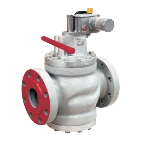
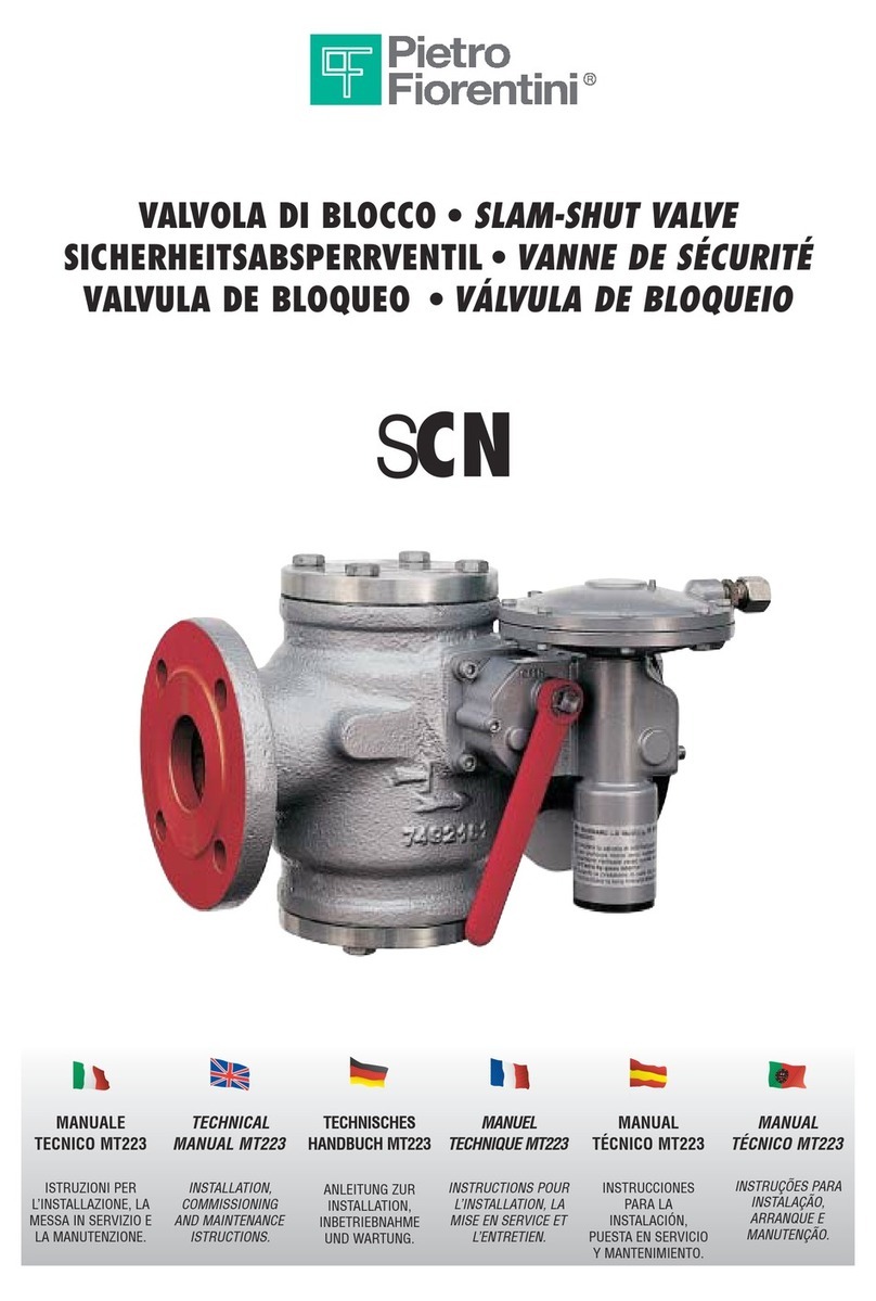
PIETRO FIORENTINI VS/AM 58 User manual

MT-302-I
ENGLISH
SAFETY
VALVE VS/AM 58
TECHNICAL MANUAL
INSTRUCTIONS FOR INSTALLATION,
COMMISSIONING AND
MAINTENANCE
TECHNICAL M

Technical Manual MT 302-I
1
WARNINGS
GENERAL WARNINGS
The equipment described in this manual is a device subject to pressure
installed in pressurized systems.
The equipment in question is normally installed in systems which
transport flammable gases (for example natural gas).
WARNINGS FOR OPERATORS
Before installation, commissioning or maintenance, operators must:
take note of the safety regulations applicable to the installation
in which they must work;
obtain the necessary permits to operate when required;
acquire the necessary personal protective equipment (helmet,
goggles, etc.);
ensure that the area in which they operate is equipped with
the required collective protection and the necessary safety
information.
PACKAGING
The packaging for transporting the equipment and related spare parts
have been specifically designed and manufactured in order to prevent
damage during normal transportation, storage and handling activities.
Therefore the equipment and spare parts must be kept in their
respective original packaging until their installation at the final site. On
opening the packaging, the condition of the materials contained within
should be checked. In the event of damage, report the damage to the
supplier keeping the original packaging for inspection.
HANDLING
The equipment and its components must be handled after ensuring
that the lifting means are adequate for the loads to be lifted (lifting
capacity and functionality).
The equipment must be handled, when required, using the lifting points
provided on the equipment itself. The use of motorized means is
reserved for the persons in charge.
INSTALLATION
The installation of the valve must comply with the regulations (laws or
standards) in force in the place of installation.
In particular, systems for natural gas must possess characteristics in
accordance with the legal requirements or regulations in force at the
installation site or at least in accordance with EN 12186 or EN 12279;
in particular paragraphs 6.2, 7.5.2, 7.7 and 9.3 of EN 12186 and 6.2,
7.4, 7.6 and 9.3 of EN 12279 must be adhered to. Installation in
accordance with these standards minimizes the risk of a fire hazard
and the formation of potentially explosive atmospheres.
The equipment is without internal pressure limiting devices, therefore, it
must be installed making sure that the operating pressure of the unit on
which it is installed never exceeds the maximum permissible pressure
value (PS).
The user should therefore provide, when it is deemed necessary,
for the installation on all adequate pressure limiting systems; he must
also set up the system with appropriate venting or drainage systems in
order to discharge the pressure and the fluid contained in the system
before carrying out any inspection and maintenance activities.
If the installation of the equipment requires the field application of
compression fittings, these must be installed in accordance with the
instructions of the manufacturer of the fittings themselves. The choice
of the fitting must be compatible with the use specified for the
equipment and with the specifications of the system when provided for.
COMMISSIONING
Commissioning must be carried out by properly trained personnel.
During the commissioning activities, personnel who are not strictly
necessary must be kept at a distance and the forbidden area must be
suitably marked (signs, barriers, etc.).
Make sure that the equipment settings are those requested; if
necessary, reset them to the required values in accordance with the
procedures indicated in this manual.
During commissioning the risks associated with any discharges to the
atmosphere of flammable or noxious gases must be evaluated.
For installation on distribution networks for natural gas you must
consider the risk of formation of explosive mixtures (gas / air) inside the
piping.
COMPLIANCE WITH DIRECTIVE 97/23 / EC (PED)
The VS/AM 58 valve is classified as a pressure accessory according to
Directive 97/23/EC (PED).

Technical Manual MT 302-I
2
ERRORE. IL SEGNALIBRO NON È DEFINITO.
WARNINGS ___________________________ 1
GENERAL WARNINGS ___________________________ 1
WARNINGS FOR OPERATORS _____________________ 1
PACKAGING ___________________________________ 1
HANDLING ____________________________________ 1
INSTALLATION _________________________________ 1
COMMISSIONING ______________________________ 1
COMPLIANCE WITH DIRECTIVE 97/23 / EC (PED) _____ 1
1.0 INTRODUCTION ___________________ 4
1.1 MAIN FEATURES _________________________ 4
1.2 SETTING SPRINGS ________________________ 4
1.3 DESCRIPTION OF OPERATION ______________ 4
1.4 VALVE SIZING ___________________________ 4
2.0 INSTALLATION ____________________ 5
2.1 GENERAL WARNINGS _____________________ 5
2.2 GENERAL REQUIREMENTS _________________ 5
2.3 SPECIAL REQUIREMENTS __________________ 5
2.3 REACTION FORCES DUE TO DISCHARGE ______ 5
2.5 CONDITIONS OF USE ______________________ 6
2.6 INSTALLATION DIRECTLY ON LINE ___________7
2.7 INSTALLATION WITH SHUT-OFF VALVE _______7
3.0 COMMISSIONING__________________7
3.1 PRESSURIZATION _________________________7
3.2 CONTROL OF THE OUTER SEAL ______________ 8
3.3 CONTROL OF THE INNER SEAL ______________8
3.4 COMMISSIONING WITH INSTALLATION DIRECTLY
ON LINE (FIG. 4) ________________________________8
3.5 COMMISSIONING WITH SHUT-OFF VALVE (FIG.
5) _______________________________________8
4.0 MAINTENANCE____________________8
4.1 GENERAL INFORMATION___________________ 8
4.2 DISASSEMBLY ____________________________8
4.3 REASSEMBLY ____________________________9
4.4 CHECKING SEALS AND CALIBRATION _________9
5.0 LUBRICATION ____________________10
6.0 STORAGE _______________________10
7.0 SPARE PARTS ____________________10
- CONTENTS -

Technical Manual MT 302-I
3
Figure 1

Technical Manual MT 302-I
4
1.0 INTRODUCTION
The purpose of this manual is to provide essential information for the
installation, commissioning, disassembly, re-assembly and
maintenance of the safety valves model VS/AM 58.
It is also considered appropriate to provide a brief illustration of the
main features of the valve.
In figure 1 a functional diagram of the valve is shown.
1.1 MAIN FEATURES
The VS/AM 58 valves are safety devices suitable for use with
previously filtered, non-aggressive gaseous fluids.
Such valves may be installed either on ducts or on pressure vessels.
Without external control sources aside from the process fluid itself,
these valves discharge a certain amount of gas at a certain calibration
pressure and then close when pressure is restored below the set
value.
The VS/AM 58 valve is a spring-loaded direct-acting valve with the
following main features.
-body design pressure (PS): 100 bar
-design temperature: -20 ÷ 60° C
-triggering range (Who): 15 ÷ 43 bar
1.2 SETTING SPRINGS
The calibration fields are the following:
ORANGE spring (2702080) - 15 ÷ 18 bar
RED spring (2702290) - 18.001 ÷ 25 bar
GREEN spring (2702460) - 25,001 ÷ 30 bar
BLACK spring (2702660) - 30,001 ÷ 43 bar
1.3 DESCRIPTION OF OPERATION
It is based on the comparison between the thrust on the piston 4
deriving from the gas pressure to control and the thrust deriving from
the setting spring 21.
The weight of the mobile unit and the static and dynamic residual
thrusts on the obturator 4 affect this comparison.
When the thrust deriving from the gas pressure exceeds that of the
setting spring, the obturator 4 is raised and a certain amount of gas is
discharged.
As soon as the pressure drops below the set value, the obturator re-
closes. Triggering of the relief valve can be controlled and adjusted by
appropriately turning the adjusting ring nut 9.
The device is designed in such a way that any breakage to one of the
main constituent parts of the valve or the pilot device leads to the
opening of the valve itself; in fact:
1.4 VALVE SIZING
The VS/AM 58 valve is sized using the given formula:
Where:
Qm= maximum flow rate to discharge in kg/h
Kd= discharge coefficient
Kdr = declassified discharge coefficient (0,9Kd)
C = expansion coefficient
p0= calibration pressure plus 10% in absolute bars
A = minimum passage area in mm2(see table 1)
M = molecular weight of fluid in kg/kmol
Z = compressibility factor of the fluid under discharge conditions (= 1 if
unknown)
T0=temperature of fluid at valve inlet in Kelvin degrees
k = isentropic equation coefficient
Table 1
Rated inlet size
1”
Minimum diameter [mm]
23
Minimum passage area [mm2]
415.48

Technical Manual MT 302-I
5
2.0 INSTALLATION
2.1 GENERAL WARNINGS
Before installation, commissioning or maintenance, operators must:
-Take note of the safety regulations applicable to the
installation in which they must work;
-Obtain the necessary permits to operate when required;
-Acquire the necessary personal protective equipment
(helmet, goggles, etc.);
-Ensure that the area in which they operate is equipped with
the required collective protection and the necessary safety
information.
The equipment and its components must be handled after ensuring
that the lifting means are adequate for the loads to be lifted (lifting
capacity and functionality). The equipment must be handled using the
lifting points provided on the equipment itself.
The use of motorized means is reserved for the persons in charge.
If the installation of the equipment or its accessories requires the
application of compression fittings, these must be installed following
the instructions of the manufacturer of the fittings themselves. The
choice of fittings must be compatible with the use specified for the
equipment and with the specifications of the system when provided for.
Commissioning must be carried out by properly trained personnel:
during commissioning activities, personnel who are not strictly
necessary must be kept at a distance and the forbidden area must be
suitably marked (signs, barriers, etc.).
2.2 GENERAL REQUIREMENTS
The valve must be installed in compliance with the regulations (laws or
standards) in force in the place of installation.
In particular, systems for natural gas must possess features in
accordance with the legal requirements or regulations in force at the
installation site or at least in accordance with EN 12186 or EN 12279
(please note that installation in compliance with these regulations
minimizes the risk of fire hazard).
The valve must be installed making sure that the operating pressure of
the unit on which it is installed never exceeds the maximum
permissible pressure value (PS).
The user must also set up the system with appropriate venting or
drainage systems in order to discharge the pressure and the fluid
contained in the system before carrying out any inspection and
maintenance activities.
The pilot of the valve is sealed after being tested and calibrated; the
sealing is done in three points:
On the adjustment plug
2.3 SPECIAL REQUIREMENTS
Before installing the valve, you must ensure that:
-The valve can be inserted in the space provided and is
sufficiently accessible for subsequent maintenance
operations Table 2 shows the dimensions and weights;
-In the case of installation with horizontal flow direction, the
upstream and downstream piping is at the same level as the
input and output connections;
-The upstream piping (and downstream only if installed with
horizontal flow direction) can bear the weight of the valve;
-The inlet / outlet flanges of the piping are parallel to the
valve sealing surfaces;
-The inside of the valve is clean and the valve itself has not
been damaged during transport;
-The upstream piping has been cleaned in order to expel
residual impurities such as welding slag, sand, paint
residues, water, etc ..;
Install the valve taking into consideration that the direction of flow is
required and is indicated with an arrow on the body of the valve itself.
The connections to the input and output pipes are done using standard
flanges whose sizes and types are indicated on the rating plate (see
section 2.4); the choices of connecting screws and seals must be
made by the installer considering this information and the conditions of
use at the installation site.
N.B The valve is designed to operate at atmospheric
backpressure (=0). Please pay attention in ensuring compliance with
the valve design conditions during the sizing of the line downstream of
the valve itself.
NOTE: the correct sizing of the discharge line downstream of the valve
is the responsibility of the system designer.
2.3 REACTION FORCES DUE TO
DISCHARGE
After opening of the valve due to overpressure of the control fluid,
reaction forces are generated due to the motion of the fluid. These
forces are then transmitted to the junctions and couplings in the valve
installation phase. The designer of the system is therefore responsible
to provide appropriate supports to correctly withstand the dynamic
forces generated.
When calculating the reaction forces with gas, refer to standard API
520-Part II (August 2003):

Technical Manual MT 302-I
6
2.5 CONDITIONS OF USE
It is recommended to check, before commissioning, that the conditions
of use conform to the features of the device.
These specifications are recalled on the rating plates with which each
valve is provided (figure 3).
The meaning of the symbols shown on the rating plate is shown below:
Safety valve the valve model
PS maximum allowable pressure
S. n. serial number
T permitted service temperature
DN rated diameter of valve and type of flanging (if
included)
Flow area: Diameter corresponding to minimum cross-
section
Set press. Calibration value
Fluid Fluid
Overpress. Overpressure to which the declared Kd value
refers
Kdr declassified discharge coefficient
In particular, it draws attention to the following features:
-Maximum allowable pressure PS
-Design temperature T (the minimum and maximum value
are shown)
-The class of the input and output connections
Moreover the user must verify that the materials used and the surface
treatments which may have been applied are compatible with the
intended use.
Given the geometric features of the valve, in the design phase certain
stresses from traffic, wind or earthquakes were not considered.
Therefore, the user must take appropriate precautions to reduce the
effects on all of these events when they are expected.

Technical Manual MT 302-I
7
Fig. 5 –Overall dimensions
2.6 INSTALLATION DIRECTLY ON LINE
When the safety valve is installed directly on the line, namely
without interposing a shut-off valve.
2.7 INSTALLATION WITH SHUT-OFF VALVE
V2 Downstream shut-off valve
6 Air vent valve
15 VS/AM relief valve...
16 Shut-off valve
17 Pressure outlet
C Controlled auxiliary pressure
3.0COMMISSIONING
3.1 PRESSURIZATION
After installation, check that the connections to the line have been
carried out properly and that any relief and discharge valves on the
system are closed and that the inlet/outlet shut-off valves, bypass valves
and the air vent valve are closed.
It is recommended to check, before commissioning, that the conditions
of use conform to the features of the equipment. These features are
shown with symbols on the equipment’s rating plates.
Slowly pressurize the system (or the system section) by means of the
upstream process valve or other systems provided for this purpose.

Technical Manual MT 302-I
8
Make sure that pressure is lower than that for which the valve was
calibrated and the temperature of the gas does not cause malfunctions.
3.2 CONTROL OF THE OUTER SEAL
The leak test of the connections of the valve to the system should be
carried out as prescribed in the installation site.
The outer seal is guaranteed when sprinkling the pressure element with
a foaming agent, no bubbles form.
3.3 CONTROL OF THE INNER SEAL
The inner seal can be checked with the valve in the closed position,
keeping the line pressure at its inlet and checking that downstream of
the valve there is no fluid leakage.
3.4 COMMISSIONING WITH INSTALLATION
DIRECTLY ON LINE (FIG. 4)
When the relief valve is installed directly on the line, namely without
interposing a shut-off valve, proceed as follows:
1) Make sure that the downstream shut-off valve
V2 and the air vent valve 6 are closed.
2) Increase pressure in the upstream segment to the intended triggering
value in one of the following ways:
- if the spring installed on the regulator/pilot allows it, increase
calibration of the pilot regulator until it reaches the desired value;
- connect an auxiliary controlled pressure to the valve 6 and stabilize it
at the desired value;
3) Check triggering of the relief valve and, if needed, adjust it by turning
the adjustment plug 9 appropriately (clockwise to increase the setting
and counterclockwise to decrease it).
3.5 COMMISSIONING WITH SHUT-OFF
VALVE (FIG. 5)
In case of installation with shut-off valve:
Close the shut-off valve 16.
2) Connect an auxiliary controlled pressure to the outlet 17 and slowly
increase it to the intended triggering level
3) Check triggering of the relief valve and, if needed, adjust it by turning
the adjustment plug 9 appropriately (for VS/AM 58) (clockwise to
increase the setting and counterclockwise to decrease it).
4.0 MAINTENANCE
4.1 GENERAL INFORMATION
The inspection and maintenance operations are closely related to the
type of installation. Preventive maintenance is therefore always
recommended, the intervals of which, if not established by regulations,
depend on:
-The quality of the transported fluid;
-The state of cleanliness and conservation of the piping
making up the system; in general, after the first start-up of
the plants, they require more frequent maintenance for the
precarious state of cleanliness inside the piping.
It is recommended to periodically check the cut-out value of the valve
following the rules in force in the place of installation and, as
necessary, to provide for a preventive maintenance of the valve and its
pilot.
Regular checks will also affect the status of the external surfaces of the
valve. In particular, one will have to restore the surface protection
(usually paint) in case of their deterioration.
Before carrying out any work, make sure that the section of the system
in which one operates has been cut off upstream and downstream and
that the pressure has been discharged into the affected pipe section.
Also make sure you have a set of recommended spare parts. The
spares must be original Pietro Fiorentini parts.
N.B. The use of non-original spare parts relieves the manufacturer of
any liability.
If your qualified staff takes care of this
maintenance, before disassembly, we recommend applying reference
signs on parts which could pose problems of direction or mutual
positioning when reassembling them.
Also remember that the O-rings and mechanical
sliding parts (rods, etc.) must be lubricated with a thin coat of silicone
grease before reassembling them.
4.2 DISASSEMBLY
With the exception of the OR valve seat (21), where the use of a
special key is required, for the disassembly of all the other components
special keys are not necessary.
Before disassembling, place the reference marks on the
elements to be disassembled.
You should take particular care not to damage the sealing seats and
housings of the sealing rings.
Examine the status of all the rubber parts affected by the seal and
replace damaged ones or those that have been in use for a long time.
Lubricate the surfaces of the moving parts with a thin coat of grease as
described in Chapter 5.
4.2.1 Disassembly and maintenance of the valve
Proceed according to the steps described below for disassembly and
maintenance of the valve, with reference to the parts in the diagram in
Figure 6.
1. Loosen the ring nut pos ○
8 .
2. Loosen and remove the adjustment plug pos ○
9 .
3. Remove the spring pos ○
21 .
4. Loosen and remove the valve seat pos ○
2
Technical Manual MT 302-I
9
5. Remove the obturator guide-valve obturator unit
6. Separate it by unscrewing the lock screw pos ○
3.
7. Replace all the components belonging to the spare
parts kit.
4.3 REASSEMBLY
Reassemble the parts, using the references put on the parts in the
disassembly phase, to correctly match all the connections and
following the procedures described in the preceding paragraphs in
reverse order
1- Reassemble the obturator guide-obturator unit.
2- Refit it inside the body pos. ○
1 .
3- Screw the valve seat pos ○
2onto the body.
4- Position the spring pos ○
21 and the spring holder plug pos
○
9.
4.4 CHECKING SEALS AND CALIBRATION
1- See par.3.3 for this check.
2- Secure the spring holder plug pos ○
9by means of the ring
nut pos ○
8.

Technical Manual MT 302-I
10
Figure 6
5.0 LUBRICATION
The valves are already lubricated during assembly (with the product
most suitable for the exercise if specified in the order) for the following
reasons:
1. To facilitate the fitting of components.
2. To improve functionality.
3. To facilitate preservation in case of warehouse storage
During normal operation it is not necessary to provide for lubrication of
the valve.
When performing maintenance, it is recommended to lubricate the
moving parts (obturator) and seals with silicone grease.
6.0 STORAGE
The VS/AM 58 valves do not require special precautions in the event of
storage for long periods; however it is important to:
-Keep the valves in the original packaging;
-Keep the protections applied in factory on the flanged
connections;
-Keep the rubber parts away from exposure to direct sunlight
to avoid rapid aging
7.0 SPARE PARTS
For the identification of spare parts refer to figure 7
When ordering spare parts specify:
Entrata Inlet
Scarico
Exhaust

Technical Manual MT 302-I
11
Type of valve
Serial number
Year of manufacture
Type of fluid used
Number of article
Quantity

Technical Manual MT 226-I
12
Figure 7
Other manuals for VS/AM 58
1
Table of contents
Other PIETRO FIORENTINI Control Unit manuals

PIETRO FIORENTINI
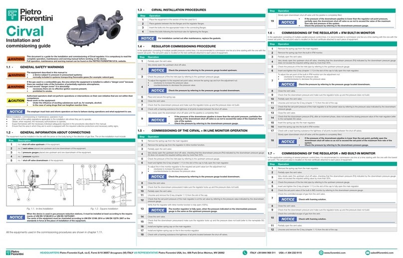
PIETRO FIORENTINI Cirval 200 User manual

PIETRO FIORENTINI
PIETRO FIORENTINI SBC 782 User manual

PIETRO FIORENTINI
PIETRO FIORENTINI SBC 782 User manual

PIETRO FIORENTINI
PIETRO FIORENTINI SBC 187 User manual

PIETRO FIORENTINI
PIETRO FIORENTINI SBC 782 User manual

PIETRO FIORENTINI
PIETRO FIORENTINI SCN User manual

PIETRO FIORENTINI
PIETRO FIORENTINI DELTAFLUX MT100 User manual

PIETRO FIORENTINI
PIETRO FIORENTINI PVS 782 User manual

PIETRO FIORENTINI
PIETRO FIORENTINI VSAM 65 BP User manual

PIETRO FIORENTINI
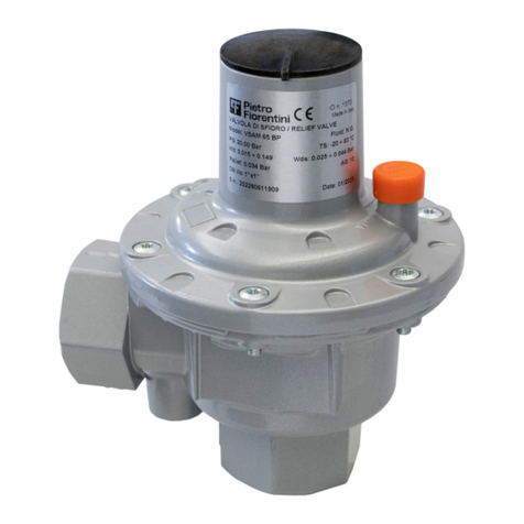
PIETRO FIORENTINI VS/AM 58 User manual