PiiGAB M-Bus 810 User manual

Description
User Manual
PiiGAB
www.PiiGAB.se
PiiGAB M-Bus 810

ETHERNET / M-BUS GATEWAY 810
Description
User Manual
Copyright PiiGAB Process Information i Göteborg AB
Anders Carlssons gata 7, S-417 55 Göteborg, Sweden
Phone +46 (0)31 55 99 77
All rights reserved.
PiiGAB are registered trademark of Processinformation i Göteborg AB.
Microsoft, Windows, Windows NT, Windows 2000, Windows XP and Windows Server 2003
are either trademarks or registered trademarks of Microsoft Cooperation in the United States
and other countries. All other trademarks are the property of their respective owners.

Contents
GENERAL......................................................................................................................41
1.1 ABOUT THIS MANUAL ....................................................................................................4
1.2 FUNCTION OVERVIEW ....................................................................................................4
1.3 BENEFITS AND POSSIBILITIES .........................................................................................4
TECHNICAL STRUCTURE ........................................................................................52
2.1 CONNECTIONS................................................................................................................5
2.2 INDICATIONS..................................................................................................................6
2.3 TECHNICAL SPECIFICATIONS ..........................................................................................6
2.4 SUPPLY VOLTAGE...........................................................................................................6
2.5 M-BUS SPECIFICATIONS.................................................................................................7
2.6 ETHERNET CONNECTION ................................................................................................7
2.7 SERIAL CONNECTION (RS232) .......................................................................................7
2.8 DRAWINGS.....................................................................................................................8
2.9 COMMUNICATION CABLES .............................................................................................9
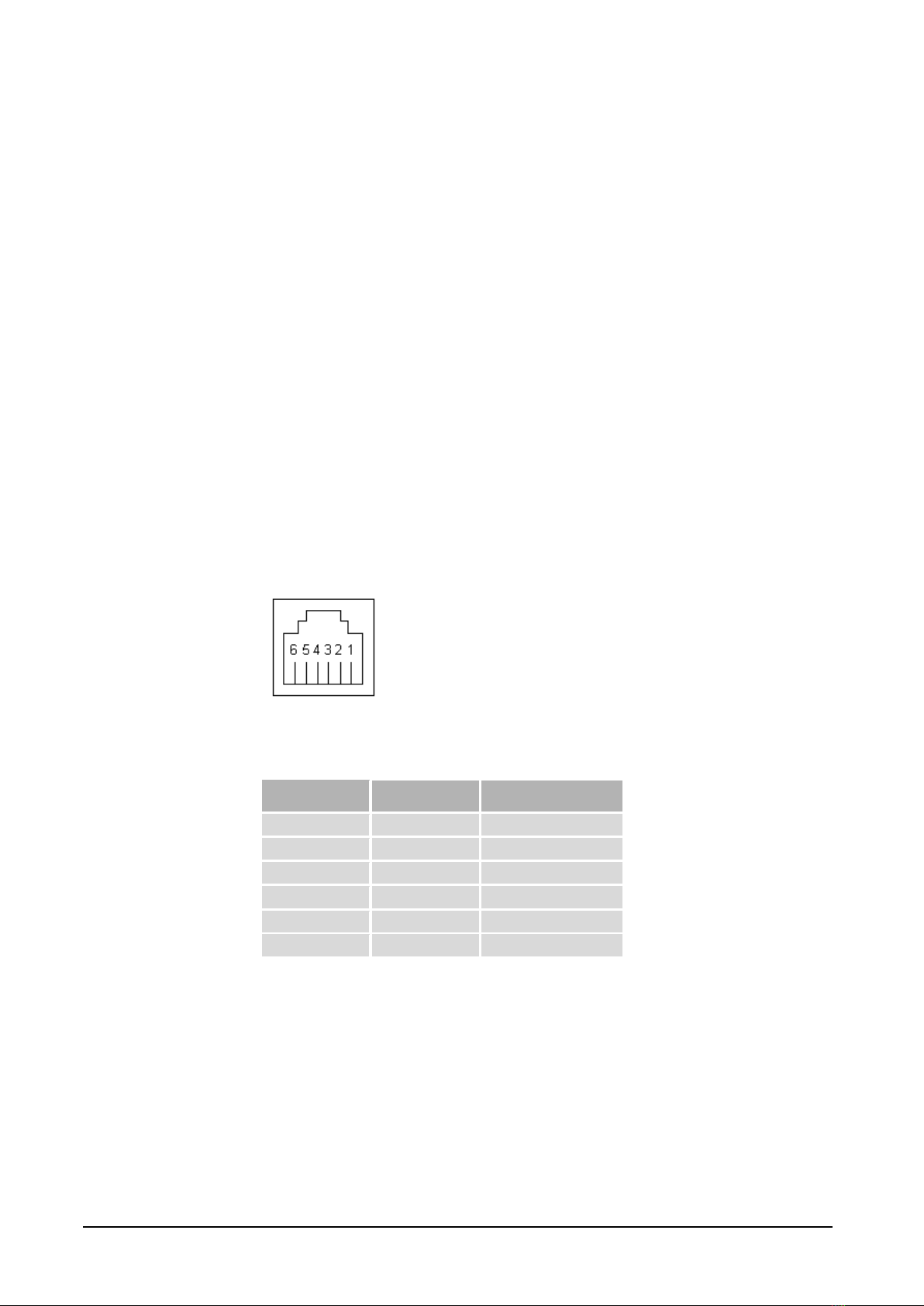
2.9.1 Pin connection for module contact RJ12 ................................................................9
2.9.2 Adapter 1: Serial to M-Bus...................................................................................10
2.9.3 Adapter 2: Configuration......................................................................................10
2.9.4 Adapter 3: Ethernet to serial port.........................................................................10
2.9.5 Adapter 4 and 5: Spy.............................................................................................11
GET STARTED STEP BY STEP ...............................................................................123
3.1 NECESSARY INFORMATION ..........................................................................................12
3.1.1 Hardware address.................................................................................................12
3.1.2 IP Address.............................................................................................................12
3.1.3 TCP/UDP..............................................................................................................12
3.1.4 Port number..........................................................................................................12
3.2 USING M-BUS WIZARD................................................................................................13
3.3 ADJUSTMENTS FOR TCP/UDP AND PORT NUMBER ......................................................13
3.4 COMMUNICATION TOWARD METERS ............................................................................14
3.4.1 The right communication speed............................................................................14
3.4.2 Adjusting the meter’s communication speed.........................................................14
3.4.3 Manufacturer specific configuration software......................................................14
3.4.4 Important parameter adjustments.........................................................................14
M-BUS WIZARD .........................................................................................................154
4.1 STARTING M-BUS WIZARD..........................................................................................15
4.2 FINDING THE GATEWAY AND CHANGE IP ADDRESS......................................................16
4.3 COMMUNICATION TEST (PING).....................................................................................19
4.4 CONFIGURATION PARAMETERS ....................................................................................20
4.5 METER SETTINGS .........................................................................................................23
OTHER CONFIGURATION METHODS.................................................................285
5.1 USING THE SERIAL PORT...............................................................................................28
5.2USING TELNET.............................................................................................................29

D E N M O D E R N A M - B U S T E K N O L O G I N
SERIAL COMMUNICATION CABLES...................................................................316
6.1 GENERAL INFORMATION..............................................................................................31
6.2 SERIAL TO M-BUS........................................................................................................31
6.3 CONFIGURATION..........................................................................................................32
6.4 ETHERNET TO SERIAL...................................................................................................32
6.5 SPY ..............................................................................................................................32
DEVICE INSTALLER ................................................................................................347
COM PORT REDIRECTOR......................................................................................368
8.1 INTRODUCTION TO COM PORT REDIRECTOR ................................................................36
8.1.1 Overview...............................................................................................................36
8.1.2 Non-Redirected Connection vs. Redirected Connections......................................37
8.2 INSTALLING COM PORT REDIRECTOR ..........................................................................38
8.3 CONFIGURATION..........................................................................................................43
8.3.1 General Configuration Guidelines........................................................................43
8.3.2 General Com Port Redirector Usage Guidelines .................................................43
8.3.3 Redirector Configuration......................................................................................44
8.3.4 Verifying Connectivity with the gateway...............................................................46
APPENDIX ...................................................................................................................479
9.1 CONTACTS ...................................................................................................................47

T H E M O D E R N M - B U S T E C H N O L O G Y
PiiGAB Process Information i Göteborg AB
4
810M.E.1.14
General1
1.1 About this manual
This manual will hopefully give you the guidance you need to connect the
Ethernet/ 810 M-Bus gateway to your network. This manual also describes how
the software M-Bus Wizard, Device Installer, and Com Port Redirector works.
These software programs are on the attached CD or you can download them from
our WebPages.
1.2 Function overview
The PiiGAB 810 gateway is working like an interface between Ethernet and the M-
Bus wire. The gateway is transparent, which means that the questions asked
through the Ethernet are being forwarded onto the electrical M-Bus interface. The
same applies to the answers from the meters that are being sent over the
Ethernet to the superior system. The gateway also works as a pure serial M-Bus
gateway.
1.3 Benefits and possibilities
The gateway can be used on either 10 or 100 Mbit network.
The possibility to choose between TCP/IP or UDP/IP
SNMP for network surveillance
The gateway can be used with a fixed IP or a dynamic IP via DHCP
It is totally independent from the operating system, which means it can be
used both by Linux and Windows.
If there is a need for high safety in the network the data traffic can be
encrypted with up to a total of 256 bites. This is an extra, which you need
to request before ordering.
Can work as TCP client or server
The possibility to set a password to prevent unauthorized to change the
configuration.
Chapter
1

T H E M O D E R N M - B U S T E C H N O L O G Y
PiiGAB Process Information i Göteborg AB
5
810M.E.1.14
Technical structure2
The interface of the gateway consists of an Ethernet connection, a serial port, four
parallel outputs for the M-Bus connections, and a connection for voltage supply.
There is also a possibility to connect a safety earth when the gateway is being
used in environments with a lot of disturbance.
On the front of the gateway there are three diode lamps that are indicating the
voltage feed, transmit and response of the M-Bus messages. The voltage diode
lamp has different behaviors depending on normal running, short circuit, or
overload of the M-Bus loop.
2.1 Connections
In the table bellow you will find information about how to connect to the 12 pins
screw terminal.
Table 2-1. Connections
Connection
Term
Description
1
AC/DC+
The gateway is powered by 24V AC or DC. When
DC is used connect the positive + cable to
connection 1.
2
AC/DC-
When DC is used connect the negative –cable to
connection 2.
3
GND
This connection is used when it is problem with
disturbances or interferences at the main power
line or the M-Bus loop.
4
--
Not used
5
M-Bus
Connection for M-Bus loop 1
6
M-Bus
Connection for M-Bus loop 1
7
M-Bus
Connection for M-Bus loop 2
8
M-Bus
Connection for M-Bus loop 2
9
M-Bus
Connection for M-Bus loop 3
10
M-Bus
Connection for M-Bus loop 3
11
M-Bus
Connection for M-Bus loop 4
12
M-Bus
Connection for M-Bus loop 4
Chapter
2

T H E M O D E R N M - B U S T E C H N O L O G Y
PiiGAB Process Information i Göteborg AB
6
810M.E.1.14
2.2 Indications
There are three diode lamps on the gateway Pwr, Tx, and Rx.
The Pwr diode lamp provides three different types of information. The red power
diode normally has a firm red light. If the power diode flashes at a 5 Hz frequency
there has been a short circuit on the M-Bus loop. If it flashes at a lower frequency
(1 Hz) the loop has been overloaded. The M-Bus gateway is available as either a
20 or a 60 device master. If those numbers are exceeded there will be a lower
frequency flash.
The Tx diode lamp has a flashing green light when the gateway is sending out a
question onto the M-Bus loop.
The Rx diode lamp has a flashing green light when the gateway receives an
answer from one of the meters connected to the M-Bus loop.
2.3 Technical specifications
Table 2-2. Technical specifications
Connection
Description
Supply voltage
24V AC/DC (local supply)
Rated Current
350mA (24V AC, 60 slaves)
250mA (24V AC, 5 and 20 slaves)
Operating temperature
-20°C till +55°C
Storage temperature
-35°C till +70°C
Dimension
WxHxD 70x86x57
Weight
120 g
Protection type
IP 20
Housing material
Lexan 940 / VO 1550
M-Bus
EN 1434-3
Emission
EN 50 022 class B radiation
EN 50 022 class B conducted
Immission
EN 61 000-4-2
EN 61 000-4-6
ENV 50 140
ENV 50 240
IEC 1000-4-2
2.4 Supply voltage
The gateway should be supplied from a local 24 AC/DC transformer. If using a
central 24 DC power supply you should mount a DC/DC converter between the
gateway and the central power.

T H E M O D E R N M - B U S T E C H N O L O G Y
PiiGAB Process Information i Göteborg AB
7
810M.E.1.14
Female socket
Male plug
Female socket
Male plug
2.5 M-Bus specifications
Table 2-3. M-Bus specifications
Connection
Description
Communication speed
300 –9600 bps
(Normal 300 or 2400 bps)
Voltage ground level (”1”)
40V (±1V)
Voltage zero level (”0”)
28V (±1V)
Short circuit level
140mA
Internal resistance
<100 Ohm
Number of units
20 or 60
(each unit maximum load 1.5mA)
2.6 Ethernet connection
Communication speed: 300 –230000bps
Connector type: 8 Position Modular (RJ45)
2.7 Serial connection (RS232)
Communication speed: 300 –38400bps
Connector type: 6 Position Modular (RJ12)

T H E M O D E R N M - B U S T E C H N O L O G Y
PiiGAB Process Information i Göteborg AB
8
810M.E.1.14
2.8 Drawings
Figure 2-1. Cabinet

T H E M O D E R N M - B U S T E C H N O L O G Y
PiiGAB Process Information i Göteborg AB
9
810M.E.1.14
Female socket
2.9 Communication cables
The serial port can be used in four different ways with the help of five different
adapters.
The following four ways are possible
Serial to M-Bus
Configuration of the gateway
Ethernet to the serial port
Spy possibility
2.9.1 Pin connection for module contact RJ12
In figure 2-2 the pin location in the female module contact RJ12 in the gateway
are shown
Figure 2-2 Pin description RJ12 socket
Table 2-4. Connections in module contact RJ12
Pin Number
Direction
Comment
1
GND
Ground
2
Rx
M-BusSerial
3
Rx
SerialEthernet
4
Tx
EthernetSerial
5
Tx
SerialM-Bus
6
N/A
Not used
The following section describes the different adapters that can be connected to the
gateway. A more detailed description including examples can be found in
chapter 6.

T H E M O D E R N M - B U S T E C H N O L O G Y
PiiGAB Process Information i Göteborg AB
10
810M.E.1.14
2.9.2 Adapter 1: Serial to M-Bus
To communicate through the serial port directly to M-Bus adapter 1 is used.
Connect the adapter to the COM port on the computer and the straight module
cable between the adapter and the RJ-12 contact on the gateway.
Table 2-5. Connection for adapter 1
9-pin DSUB/F
RJ12/F
Pin 2 (RxD)
Pin 2
Pin 3 (TxD)
Pin 5
Pin 5 (GND)
Pin 1
2.9.3 Adapter 2: Configuration
When configuration is to be made via the serial port adapter 2 is used.
Connect the adapter to the COM port on the computer and the straight module
cable between the adapter and the RJ-12 contact on the gateway.
Table 2-6. Connection for adapter 2
9-pin DSUB/F
RJ12/F
Pin 2 (RxD)
Pin 3
Pin 3 (TxD)
Pin 4
Pin 5 (GND)
Pin 1
2.9.4 Adapter 3: Ethernet to serial port
If the gateway is being used as an Ethernet/RS232 gateway adapter 3 is used.
Observe that hardware handshaking can’t be connected.
Connect the adapter to the unit, which communication will be established and the
straight module cable between the adapter and the RJ-12 contact on the gateway.
Table 2-7. Connection for adapter 3
9-pin DSUB/M
RJ12/F
Pin 2 (RxD)
Pin 4
Pin 3 (TxD)
Pin 3
Pin 5 (GND)
Pin 1

T H E M O D E R N M - B U S T E C H N O L O G Y
PiiGAB Process Information i Göteborg AB
11
810M.E.1.14
2.9.5 Adapter 4 and 5: Spy
All the traffic that are being sent and received on the M-Bus port are mirrored to
the serial port. This results in that you can connect a serial analyzer or monitoring
software. To be able to read what is being written and read two communication
ports are demanded on your computer.
Through using adapter 4 and 5 monitoring can be done. Adapter 4 is used to
monitor the question and adapter 5 is used to monitor the answer.
The two adapter’s module cables are connected via a branch and onto the
gateway’s RJ-12 contact.
Table 2-8. Connection for adapter 4 (Ethernet request)
9-pin DSUB/F
RJ12/F
Pin 2 (RxD)
Pin 3
Pin 5 (GND)
Pin 1
Table 2-9. Connection for adapter 5 (M-Bus response)
9-pin DSUB/F
RJ12/F
Pin 2 (RxD)
Pin 2
Pin 5 (GND)
Pin 1

T H E M O D E R N M - B U S T E C H N O L O G Y
PiiGAB Process Information i Göteborg AB
12
810M.E.1.14
Get started step by step3
This chapter covers the different steps needed to put the M-Bus 810 gateway into
operation.
3.1 Necessary information
The connecting of the supply voltage and the M-Bus loop is made according to table
2.1.
3.1.1 Hardware address
You have to know the unit’s hardware address, which is the same as the MAC
address. The MAC address can be found on the label on one of the gables of the
unit. It has the format 00-20-4a-xx-xx-xx, where xx is a unique number for the
unit.
3.1.2 IP Address
Most of the time the gateway needs a unique IP address on your network in order
to be connected to the superior software. You can also use the automatic IP
address via DHCP if you wish. Contact the system administrator to receive the
right IP address with the belonging subnet mask and gateway. The IP address has
to be within the allowed area, unique within your network, and it has to be in the
same subnet as your PC.
3.1.3 TCP/UDP
To communicate with the superior software you have to choose between TCP or
UDP.
We do not recommend that any of PiiGAB’s products or products bought from
PiiGAB should be made public on the internet. We always recommend that a
firewall is used, not following this recommendation will be at your own risk.
3.1.4 Port number
To communicate with the gateway the port number has to be adjusted. The
default adjustment in the gateway is 10001 and can almost always be used.
Control with the network responsible what port number to use.
Chapter
3

T H E M O D E R N M - B U S T E C H N O L O G Y
PiiGAB Process Information i Göteborg AB
13
810M.E.1.14
3.2 Using M-Bus Wizard
By using the M-Bus Wizard you can set the IP address and all other important
parameters to be able to communicate with your M-Bus meter. The M-Bus Wizard
is described in chapter 4.
You can search for 810-units in your network through the Wizard. There is usually
an IP address positioned on the gateway and if the address is outside the
permitted IP address area this will be marked in red. If you still are having trouble
finding the gateway on the network you can search and configure the gateway
through the MAC address. You cannot find the gateway if it is connected to a sub
network.
3.3 Adjustments for TCP/UDP and port number
To adjust the TCP alternatively UDP the M-Bus Wizard is used, and it can be found
in chapter 4. Choose “Change Device Parameters” from the main menu and click
through to the site where you make your choice. At PiiGAB we recommend usage
of UDP if this is supported by the superior software. The reason for this is that the
M-Bus driver has complete control over how the questions and answers are being
sent.
The adjustment of the port number is made at the same place as the TCP/UDP in
the Wizard. The port number has to be the same as in the calling from the
superior software in order for contact to be established with the gateway.

T H E M O D E R N M - B U S T E C H N O L O G Y
PiiGAB Process Information i Göteborg AB
14
810M.E.1.14
3.4 Communication toward meters
3.4.1 The right communication speed
After the right IP address has been established the M-Bus loop’s communication
speed has to be adjusted. The communication speed adjusted in the Wizard has to
match the meters communication speed. Many meters have a communication
speed of 300bps at delivery. If there is a possible to set the meters at 2400bps try
to do that in order to increase the communication speed and by that improve the
performance.
When communication toward the meters has been established and by that the M-
bus loop is connected the right way, you can continue to configure the superior
software.
3.4.2 Adjusting the meter’s communication speed
In version 1.0 of the M-Bus Wizard you can control the meter on your M-Bus loop
directly via the meter’s primary address. You can also adjust functions such as
communication speed and primary address via your network. Note that some
meter makes do not support the possibility to change for example the primary
address via a standard M-Bus command.
3.4.3 Manufacturer specific configuration software
If you want to configure the meters via the meter delivery’s own software you can
do so in most cases over the network via the gateway. They usually have no
network support, so they communicate only via the communication port on the
computer. By using Comport Redirector, described in chapter 8, you can usually
use this software in your network.
3.4.4 Important parameter adjustments
Some issues to keep in mind regarding communication between the meter and the
superior software is the time interval between the questions, the number of
telegram that can be read by the meter, and what communication speed that has
been chosen. Some meters has up to 40 telegrams that can be read at a adjusted
transference speed of 300bps, and therefore take along time.
The M-Bus driver for the SCADA program Citect, which has been developed by
PiiGAB, is documented with great details regarding how different
parameters are being set in programs like NrOfTelegrams, InitRead etc. The
document “Citect for Windows, Version 5.xx, 6.xx M-Bus driver, User Information”
(Version: 1.01.03.001-1) is available to download at the PiiGAB website.

T H E M O D E R N M - B U S T E C H N O L O G Y
PiiGAB Process Information i Göteborg AB
15
810M.E.1.14
M-Bus Wizard4
M-Bus Wizard is a software delivered with the gateway. The software helps you to
make required adjustments in the gateway to establish communication etc. It also
gives you the opportunity to change address and communication speed on the
meters that supports the M-Bus standard, additionally you can see some parts of
the communication towards the meter.
4.1 Starting M-Bus Wizard
Copy the zip-file ”MBus 800 Family Setup Wizard 2.0.1.zip” to the appropriate
folder on the computer and open the file. Install the program by double clicking on
the Setup files or go via the control panel. After the program has been installed
you can start it by choosing the program in the start menu. If the installation has
been made with the base settings the program can be found under the PiiGAB
folder.
The first time you start the program you have to choose a language. If you later
want to change to another language it is also possible.
After the language has been chosen, the introduction picture is presented with a
summary of the M-Bus Wizard usage.
Figure 4-1. Welcome Screen
Click ”Next”to proceed.
Kapitel
4
Chapter
4

T H E M O D E R N M - B U S T E C H N O L O G Y
PiiGAB Process Information i Göteborg AB
16
810M.E.1.14
4.2 Finding the gateway and change IP address
Figure 4-2. Select what you wish to do
The next page (main menu) shows the different commands that can be made with
the M-Bus Wizard. Choose your option and click “Next.” If the gateway has not
been configured before choose Change device IP Settings and click “Next.”
Figure 4-3. Change IP settings –select connection method
In this picture you are choosing the way you want to communicate to install the IP
address. If 810 is connected to the network choose the option on top and with a
serial connection pick the lower. In this part we are assuming that the gateway is
connected to the network. On the side of the gateway there is a label with the

T H E M O D E R N M - B U S T E C H N O L O G Y
PiiGAB Process Information i Göteborg AB
17
810M.E.1.14
MAC address, which is filled out according to the picture. Click “Next” after this. If
the configuration is made via the serial port use adapter 2, see chapter 2.8.1.
Follow the Wizard instructions to co figurate this way. The difference to configure
via the network is that the voltage has to be turned on and off in order for the
settings to have an effect.
Figure 4-4. Change IP settings –enter new IP settings
Fill out the fields, IP-address, Netmask, and Gateway. If you are using DHCP
choose the upper option otherwise choose the lower. If you are going to use a
unique IP address contact the responsible for the network in order to get the
correct information. Click on “Next” to continue.
Figure 4-5. Change IP settings –update device

T H E M O D E R N M - B U S T E C H N O L O G Y
PiiGAB Process Information i Göteborg AB
18
810M.E.1.14
This picture is solely here to inform you about that the next step is to activate the
earlier made configuration like IP-address, subnet mask, and gateway address.
When you click on “Apply” the configuration starts. When the gateway is updated
with the new information click “Next” to continue.
If you already know that the gateway has an IP address that can be found via the
network choose Find Devices from the main menu as the first step instead. If the
unit is found on the network you do not have to provide MAC-number when you
are setting the IP address. Sometimes it can be hard to find the gateway and the
reason for that can be because it is in a subnet. Contact the network responsible
for further information about the network.
Figure 4-6. Outside permitted address area
If the IP address can be found outside the permitted address area, but is possible
to reach within the network, this is shown in the Wizard (see above.)
Figure 4-7. Network search complete
If the gateway can be found within the network you can see it in the above
listings. Choose the preferred meter and click “Next” to go to the main menu.

T H E M O D E R N M - B U S T E C H N O L O G Y
PiiGAB Process Information i Göteborg AB
19
810M.E.1.14
4.3 Communication test (Ping)
Figure 4-8. Ping device
The above picture will be presented to you after choosing Ping Device from the
main menu. Fill in the IP address on the gateway you want to control and push
“Ping”. If the earlier steps in the Wizard are made correctly, the chosen IP address
will show up on this page.
Figure 4-9. Ping device
If you make contact by using the Ping command the above communication result
will show. Push “Next” to continue.
Table of contents
Other PiiGAB Gateway manuals
Popular Gateway manuals by other brands

AudioCodes
AudioCodes October 2011 Hardware installation manual

Juniper
Juniper MAG2600 Hardware guide

Vonamic
Vonamic VIPCOS 910 Configuration manual

Ubee
Ubee UBC1310BA10 Quick installation guide

CONTROL SOLUTIONS
CONTROL SOLUTIONS Babel Buster 2 quick start guide

Casa Systems
Casa Systems NetComm CloudMesh NF18MESH quick start guide