Pilz PNOZ s7.1 User manual

PNOZ s7.1
Operating Manual-21865-EN-11
}Safety relays

Preface
This document is the original document.
All rights to this documentation are reserved by Pilz GmbH & Co. KG. Copies may be made
for the user's internal purposes. Suggestions and comments for improving this documenta-
tion will be gratefully received.
Source code from third-party manufacturers or open source software has been used for
some components. The relevant licence information is available on the Internet on the Pilz
homepage.
Pilz®, PIT®, PMI®, PNOZ®, Primo®, PSEN®, PSS®, PVIS®, SafetyBUS p®,
SafetyEYE®, SafetyNET p®, the spirit of safety® are registered and protected trademarks
of Pilz GmbH & Co. KG in some countries.
SD means Secure Digital

Contents
Operating Manual PNOZ s7.1
21865-EN-11 | 3
Introduction ............................................................................................................................5
Validity of documentation.......................................................................................................... 5
Using the documentation .......................................................................................................... 5
Definition of symbols................................................................................................................. 5
Safety ...................................................................................................................................... 6
Intended use ............................................................................................................................. 6
Safety regulations ..................................................................................................................... 6
Safety assessment ................................................................................................................... 6
Use of qualified personnel ........................................................................................................ 7
Warranty and liability ................................................................................................................ 7
Disposal .................................................................................................................................... 7
For your safety.......................................................................................................................... 7
Unit features ...........................................................................................................................7
Safety features ....................................................................................................................... 8
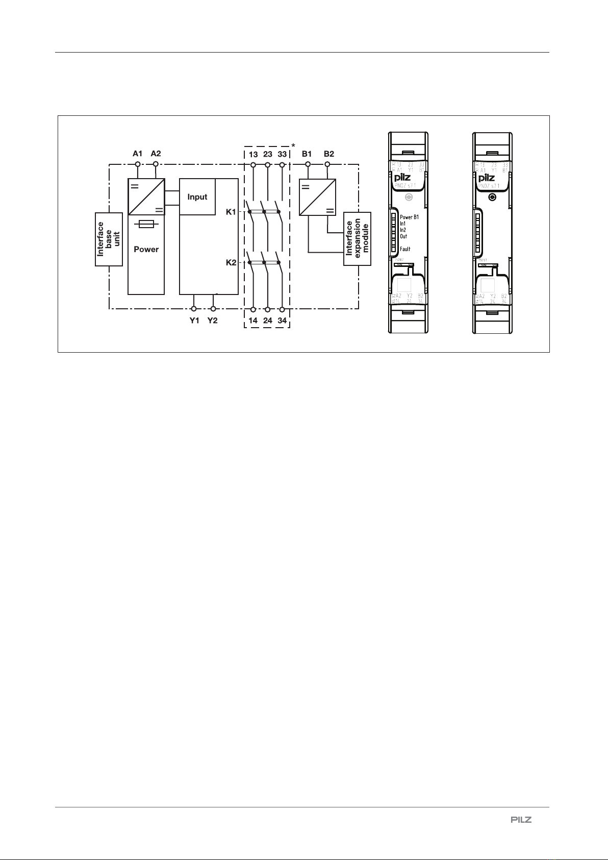
Block diagram/terminal configuration ................................................................................. 9
Function description ............................................................................................................. 9
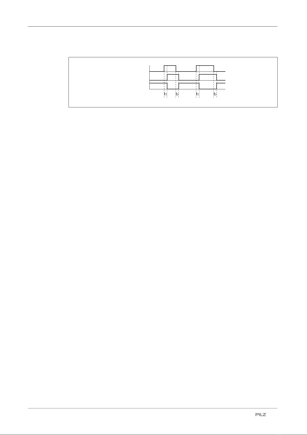
Timing diagram ......................................................................................................................... 10
Installation ..............................................................................................................................10
Wiring ......................................................................................................................................12
Preparing for operation ......................................................................................................... 13
Application examples ............................................................................................................ 14
Operation ................................................................................................................................15
Status indicators ....................................................................................................................... 16
Fault indicators ......................................................................................................................... 16
Faults - malfunctions ............................................................................................................. 16
Dimensions in mm .................................................................................................................16
Technical details ....................................................................................................................17
Safety characteristic data ......................................................................................................... 20
Classification according to ZVEI, CB24I ................................................................................... 21
Supplementary data ..............................................................................................................22
Service life graph ...................................................................................................................... 22
Permitted operating height........................................................................................................ 24

Contents
Operating Manual PNOZ s7.1
21865-EN-11 | 4
Remove plug-in terminals ..................................................................................................... 25
Order reference ......................................................................................................................25
EC declaration of conformity ................................................................................................ 25

PNOZ s7.1
Operating Manual PNOZ s7.1
21865-EN-11 | 5
Introduction
Validity of documentation
This documentation is valid for the product PNOZ s7.1. It is valid until new documentation is
published.
This operating manual explains the function and operation, describes the installation and
provides guidelines on how to connect the product.
Using the documentation
This document is intended for instruction. Only install and commission the product if you
have read and understood this document. The document should be retained for future ref-
erence.
Definition of symbols
Information that is particularly important is identified as follows:
DANGER!
This warning must be heeded! It warns of a hazardous situation that poses
an immediate threat of serious injury and death and indicates preventive
measures that can be taken.
WARNING!
This warning must be heeded! It warns of a hazardous situation that could
lead to serious injury and death and indicates preventive measures that can
be taken.
CAUTION!
This refers to a hazard that can lead to a less serious or minor injury plus
material damage, and also provides information on preventive measures
that can be taken.
NOTICE
This describes a situation in which the product or devices could be dam-
aged and also provides information on preventive measures that can be
taken. It also highlights areas within the text that are of particular import-
ance.

PNOZ s7.1
Operating Manual PNOZ s7.1
21865-EN-11 | 6
INFORMATION
This gives advice on applications and provides information on special fea-
tures.
Safety
Intended use
The contact expansion module PNOZ s7.1 meets the requirements of EN60947-5-1 and
EN60204-1. It is used to increase the number of instantaneous safety contacts available
on a base unit. Base units are all safety relays with feedback loop.
The max. achievable safety level depends on the base unit. The expansion module may not
exceed this. The safety-related characteristic values stated under safety-related character-
istic data [ 21] can only be achieved if the base unit also exhibits these safety charac-
teristic values.
The following is deemed improper use in particular
}Any component, technical or electrical modification to the product,
}Use of the product outside the areas described in this manual,
}Use of the product outside the technical details (see Technical details [ 17]).
NOTICE
EMC-compliant electrical installation
The product is designed for use in an industrial environment. The product
may cause interference if installed in other environments. If installed in other
environments, measures should be taken to comply with the applicable
standards and directives for the respective installation site with regard to in-
terference.
Safety regulations
Safety assessment
Before using a device, a safety assessment in accordance with the Machinery Directive is
required.
The product as an individual component fulfils the functional safety requirements in accord-
ance with EN ISO 13849 and EN 62061. However, this does not guarantee the functional
safety of the overall plant/machine. To achieve the relevant safety level of the overall plant/
machine’s required safety functions, each safety function needs to be considered separ-
ately.

PNOZ s7.1
Operating Manual PNOZ s7.1
21865-EN-11 | 7
Use of qualified personnel
The products may only be assembled, installed, programmed, commissioned, operated,
maintained and decommissioned by persons who are competent to do so.
A competent person is a qualified and knowledgeable person who, because of their train-
ing, experience and current professional activity, has the specialist knowledge required. To
be able to inspect, assess and operate devices, systems and machines, the person has to
be informed of the state of the art and the applicable national, European and international
laws, directives and standards.
It is the company’s responsibility only to employ personnel who
}Are familiar with the basic regulations concerning health and safety / accident prevention,
}Have read and understood the information provided in the section entitled Safety
}Have a good knowledge of the generic and specialist standards applicable to the specific
application.
Warranty and liability
All claims to warranty and liability will be rendered invalid if
}The product was used contrary to the purpose for which it is intended,
}Damage can be attributed to not having followed the guidelines in the manual,
}Operating personnel are not suitably qualified,
}Any type of modification has been made (e.g. exchanging components on the PCB
boards, soldering work etc.).
Disposal
}In safety-related applications, please comply with the mission time TM in the safety-related
characteristic data.
}When decommissioning, please comply with local regulations regarding the disposal of
electronic devices (e.g. Electrical and Electronic Equipment Act).
For your safety
The unit meets all the necessary conditions for safe operation. However, please note the
following:
}Note for overvoltage category III: If voltages higher than low voltage (>50 VAC or >120
VDC) are present on the unit, connected control elements and sensors must have a rated
insulation voltage of at least 250 V.
Unit features
}Relay outputs:
– 3 safety contacts (N/O), instantaneous
}Supply voltage for expansion modules
}LED for:
– Supply voltage at B1 and B2
– Input status, channel1
– Input status, channel2

PNOZ s7.1
Operating Manual PNOZ s7.1
21865-EN-11 | 8
– Switch status of the safety contacts
– Fault
}Plug-in connection terminals (either spring-loaded terminal or screw terminal)
}See order reference for unit types
Safety features
The unit meets the following safety requirements:
}The contact expansion module expands an existing circuit. As the output relays are mon-
itored via the base unit's feedback loop, the safety functions on the existing circuit are
transferred to the contact expandsion module.
}The safety function remains effective in the case of a component failure.
}Earth fault in the feedback loop:
Detected, depending on the base unit that is used.
}Earth fault in the input circuit:
The output relays de-energise and the safety contacts open.

PNOZ s7.1
Operating Manual PNOZ s7.1
21865-EN-11 | 9
Block diagram/terminal configuration
Fig.: Centre: Front view with cover, right: Front view without cover
*Safe separation from non-marked area in accordance with EN 60947-1,
6 kV, basic insulation between all safety contacts.
Function description
with PNOZsigma base unit:
}Dual-channel operation via PNOZsigma connector
without PNOZsigma base unit:
}Single-channel operation: one input circuit affects the output relays
}Connection for base unit
with PNOZsigma s7.2 expansion modules:
}Dual-channel operation and supply voltage via PNOZsigma connector

PNOZ s7.1
Operating Manual PNOZ s7.1
21865-EN-11 | 10
Timing diagram
POWER/Input
Output safe
Feedback
Legend
}POWER/Input: Supply voltage/Input
}Output safe: Safety contacts
}Feedback: Feedback loop
}t1: Switch-on delay
}t2: Delay-on de-energisation
Installation
Install contact expansion module without base unit:
}Ensure that the plug terminator is inserted at the side of the unit.
Connect base unit and contact expansion module PNOZ s7.1:
}Remove the plug terminator at the side of the base unit and at the left of the contact ex-
pansion module
}Connect the base unit and the contact expansion module using the connector supplied,
before mounting the units to the DIN rail.
Connect contact expansion module PNOZ s7.1 to PNOZsigma contact expansion
modules
}Connect the contact expansion modules using the connector supplied.
Control cabinet installation
}The safety relay should be installed in a control cabinet with a protection type of at least
IP54.
}Use the notch on the rear of the unit to attach it to a DIN rail (35mm).
}When installed vertically: Secure the unit by using a fixing element (e.g. retaining bracket
or end angle).
Push the unit upwards or downwards before lifting it from the DIN rail.

PNOZ s7.1
Operating Manual PNOZ s7.1
21865-EN-11 | 11
Expansion options Please note the max. power consumption of the
contact expansion modules (see technical data
PNOZs7.1).
: Base unit
: Contact expansion module PNOZs7.1
: Contact expansion module PNOZs7.2
: Contact expansion module PNOZs7.2 with ter-
minator
: Base unit
: Contact expansion module PNOZs7.1
: Contact expansion module PNOZs7.2
: Expansion module PNOZ s7, s8, s9, s10, s11 as
a terminator
: Contact expansion module PNOZs7.1 with ter-
minator
: Contact expansion module PNOZs7.2
: Contact expansion module PNOZs7.2 with ter-
minator

PNOZ s7.1
Operating Manual PNOZ s7.1
21865-EN-11 | 12
Expansion options Please note the max. power consumption of the
contact expansion modules (see technical data
PNOZs7.1).
: Contact expansion module PNOZs7.1 with ter-
minator
: Contact expansion module PNOZs7.2
: Expansion module PNOZ s7, s8, s9, s10, s11 as
a terminator
: Base unit
: Contact expansion module PNOZs7.1
: Contact expansion module PNOZs7.2
: Contact expansion module PNOZs7.1
: Contact expansion module PNOZs7.2
: Contact expansion module PNOZs7.2 with ter-
minator
Wiring
Please note:
}Information given in the "Technical details [ 17]" must be followed.
}The output contacts 13-14, 23-24, 33-34 are safety contacts.
}To prevent contact welding, a fuse should be connected before the output contacts (see
Technical details [ 17]).
}Calculation of the max. cable length lmax in the input circuit:
Rlmax
Rl / km
Imax =
Rlmax = max. overall cable resistance (see Technical details [ 17])
Rl/km = cable resistance/km
}Use copper wiring with a temperature stability of 75 °C.
}To prevent EMC interferences (particularly common-mode interferences) the measures
described in EN60204-1 must be executed. This includes the separate routing of cables
of the control circuits (input, start and feedback loop) from other cables for energy trans-
mission or the shielding of cables, for example.
}Adequate protection must be provided on all output contacts with capacitive and inductive
loads.

PNOZ s7.1
Operating Manual PNOZ s7.1
21865-EN-11 | 13
}The power supply must comply with the regulations for extra low voltages with protective
electrical separation (SELV, PELV) in accordance with VDE 0100, Part 410.
Preparing for operation
Supply voltage AC DC
Base unit:
Safety relay PNOZsigma
PNOZsigma
base unit
PNOZsigma
expansion
module
Base unit:
Safety relay PNOZX
A1
A2
24 V DC
0 V
PNOZsigma
expansion
module
Supply voltage for expansion
modules PNOZsigma
B1
B2
24 V DC
0 V
PNOZsigma
expansion
module
Input circuit Single-channel Dual-channel
Base unit:
Safety relay PNOZsigma
Base unit:
Safety relay PNOZX
A1
A2
24 V DC
0 V
PNOZsigma
expansion
module
Base unit:
Safety relay PNOZelog driven via
semiconductor outputs (24 VDC)
A1
A20 V
O1
L-
PNOZsigma
expansion
module
Start circuit/feedback loop Base unit: Safety relay PNOZX Base unit: Safety relay PNOZelog
The inputs that evaluate the feed-
back loop will depend on the
base unit and application
PNOZsigma
expansion
module
Y1
Y2
feedback
loop
Y1
Y2
24 V DC
PNOZsigma
expansion
module
feedback
loop

PNOZ s7.1
Operating Manual PNOZ s7.1
21865-EN-11 | 14
Connection to PNOZsigma
base unit/PNOZmulti Mini base
unit
Base unit: Safety relay PNOZ-
sigma
Base unit: Small control system
PNOZmulti Mini
The feedback loop is connected
and evaluated via the connector
PNOZmulti Mini
base unit
PNOZsigma
expansion
module
INFORMATION
If a base unit and a contact expansion module are linked via the connector,
no additional wiring is necessary.
Do not connect A1/A2 and Y1/Y2 to the expansion module!
Application examples
Single device
}Single-channel
}Driven via safety relay with safety contacts
.
0
40
@
&
.-=2
-)
.-.)
)-))
&.-=2
&,%'&
.
A
A. .
78*0
)
-
#3
#3
7GG
4I 4I.
.-=2
%=
Contact expansion for PNOZ s4
}Emergency stop
}Dual-channel
}with detection of shorts across contacts

PNOZ s7.1
Operating Manual PNOZ s7.1
21865-EN-11 | 15
}Monitored start
}falling edge with feedback loop monitoring
@
.
0
>
40
. .#
"8
-
.-=2
-)
.-.)
)-))
-.-
-.-=2
&,%%-
.
. .. . )-
A).
.
0
40
@
&
.-=2
-)
.-.)
)-))
&.-=2
&,%'&
.
A
A. .
.
#
.
..
)
-
#)
>
.
48*
.-=2
%=
Operation
When the relay outputs are switched on, the mechanical contact on the relay cannot be
tested automatically. Depending on the operational environment, measures to detect the
non-opening of switching elements may be required under some circumstances.
When the product is used in accordance with the European Machinery Directive, a check
must be carried out to ensure that the safety contacts on the relay outputs open correctly.
Open the safety contacts (switch off output) and start the device again, so that the internal
diagnostics can check that the safety contacts open correctly
}for SIL CL 3/PL e at least 1x per month
}for SIL CL 2/PL d at least 1x per year
NOTICE
The safety function should be checked after initial commissioning and each
time the plant/machine is changed. The safety functions may only be
checked by qualified personnel.
LEDs indicate the status and errors during operation:
LED on

PNOZ s7.1
Operating Manual PNOZ s7.1
21865-EN-11 | 16
Status indicators
POWER B1
Supply voltage applied for the expansion modules.
IN1
Channel1 actuated.
IN2
Channel2 actuated.
IN1, IN2, OUT
Safety contacts are closed.
Fault indicators
FAULT
Diagnostics: Plug terminator not connected
}Remedy: Insert plug terminator, switch supply voltage off and then on again.
Faults - malfunctions
}Contact malfunctions: If the contacts have welded, reactivation will not be possible after
the input circuit has opened.
Dimensions in mm
*with spring-loaded terminals
120 (4.72")
* 100 (3,94")
98 (3.86")
17,5
(0.69")

PNOZ s7.1
Operating Manual PNOZ s7.1
21865-EN-11 | 17
Technical details
General 750167 751167
Certifications
CCC, CE, EAC (Eurasian),
KOSHA, TÜV, cULus Listed
CCC, CE, EAC (Eurasian),
KOSHA, TÜV, cULus Listed
Electrical data 750167 751167
Supply voltage
Voltage 24 V 24 V
Kind DC DC
Voltage tolerance -20 %/+20 % -20 %/+20 %
Output of external power supply
(DC) 2 W 2 W
Residual ripple DC 20 % 20 %
Duty cycle 100 % 100 %
Max. power of all expansion mod-
ules 20 W 20 W
Inputs 750167 751167
Number 1 1
Voltage at
Input circuit DC 24 V 24 V
Current at
Input circuit DC 70 mA 70 mA
Max. inrush current impulse
Current pulse, input circuit 2 A 2 A
Pulse duration, input circuit 0,1 ms 0,1 ms
Max. overall cable resistance Rl-
max
Single-channel at UB DC 30 Ohm 30 Ohm
Relay outputs 750167 751167
Number of output contacts
Safety contacts (N/O), instant-
aneous 3 3
Max. short circuit current IK 1 kA 1 kA
Utilisation category
In accordance with the standard EN 60947-4-1 EN 60947-4-1

PNOZ s7.1
Operating Manual PNOZ s7.1
21865-EN-11 | 18
Relay outputs 750167 751167
Utilisation category of safety con-
tacts
AC1 at 240 V 240 V
Min. current 0,003 A 0,003 A
Max. current 6 A 6 A
Min. output 0,04 VA 0,04 VA
Max. power 1500 VA 1500 VA
DC1 at 24 V 24 V
Min. current 0,003 A 0,003 A
Max. current 6 A 6 A
Min. output 0,04 W 0,04 W
Max. power 150 W 150 W
Utilisation category
In accordance with the standard EN 60947-5-1 EN 60947-5-1
Utilisation category of safety con-
tacts
AC15 at 230 V 230 V
Max. current 5 A 5 A
DC13 (6 cycles/min) at 24 V 24 V
Max. current 5 A 5 A
Utilisation category in accordance
with UL
Voltage 240 V AC G.U. (same polarity) 240 V AC G.U. (same polarity)
With current 6 A 6 A
Voltage 24 V DC G. U. 24 V DC G. U.
With current 6 A 6 A
External contact fuse protection,
safety contacts
In accordance with the standard EN 60947-5-1 EN 60947-5-1
Max. melting integral 260 A²s 260 A²s
Blow-out fuse, quick 10 A 10 A
Blow-out fuse, slow 6 A 6 A
Blow-out fuse, gG 10 A 10 A
Circuit breaker 24V AC/DC,
characteristic B/C 6 A 6 A
Contact material AgCuNi + 0,2 µm Au AgCuNi + 0,2 µm Au
Conventional thermal current
while loading several contacts
750167 751167
Ith per contact at UB DC;
AC1:240V,DC1:24V
Conv. therm. current with 1 con-
tact 6 A 6 A
Conv. therm. current with 2 con-
tacts 5,5 A 5,5 A
Conv. therm. current with 3 con-
tacts 4,5 A 4,5 A

PNOZ s7.1
Operating Manual PNOZ s7.1
21865-EN-11 | 19
Times 750167 751167
Switch-on delay
With automatic start after power
on typ. 30 ms 30 ms
With automatic start after power
on max. 50 ms 50 ms
Delay-on de-energisation
With E-STOP typ. 18 ms 18 ms
With E-STOP max. 30 ms 30 ms
With power failure typ. 18 ms 18 ms
With power failure max. 30 ms 30 ms
Supply interruption before de-ener-
gisation 5 ms 5 ms
Environmental data 750167 751167
Climatic suitability EN 60068-2-78 EN 60068-2-78
Ambient temperature
Temperature range -10 - 55 °C -10 - 55 °C
Storage temperature
Temperature range -40 - 85 °C -40 - 85 °C
Climatic suitability
Humidity 93 % r. h. at 40 °C 93 % r. h. at 40 °C
Condensation during operation Not permitted Not permitted
EMC EN 60947-5-1, EN 61000-6-2, EN
61000-6-4, EN 61326-3-1
EN 60947-5-1, EN 61000-6-2, EN
61000-6-4, EN 61326-3-1
Vibration
In accordance with the standard EN 60068-2-6 EN 60068-2-6
Frequency 10 - 55 Hz 10 - 55 Hz
Amplitude 0,35 mm 0,35 mm
Airgap creepage
In accordance with the standard EN 60947-1 EN 60947-1
Overvoltage category III III
Pollution degree 2 2
Rated insulation voltage 250 V 250 V
Rated impulse withstand voltage 6 kV 6 kV
Protection type
Housing IP40 IP40
Terminals IP20 IP20
Mounting area (e.g. control cab-
inet) IP54 IP54
Mechanical data 750167 751167
Mounting position Any Any
Mechanical life 10,000,000 cycles 10,000,000 cycles
Material
Bottom PC PC
Front PC PC
Top PC PC

PNOZ s7.1
Operating Manual PNOZ s7.1
21865-EN-11 | 20
Mechanical data 750167 751167
Connection type Screw terminal Spring-loaded terminal
Mounting type plug-in plug-in
Conductor cross section with screw
terminals
1 core flexible 0,25 - 2,5 mm², 24 - 12 AWG –
2 core with the same cross sec-
tion, flexible with crimp connect-
ors, no plastic sleeve 0,25 - 1 mm², 24 - 16 AWG –
2 core with the same cross sec-
tion, flexible without crimp con-
nectors or with TWIN crimp con-
nectors 0,2 - 1,5 mm², 24 - 16 AWG –
Torque setting with screw terminals 0,5 Nm –
Stripping length with screw termin-
als 8 mm –
Conductor cross section with
spring-loaded terminals: Flexible
with/without crimp connector – 0,2 - 2,5 mm², 24 - 12 AWG
Spring-loaded terminals: Terminal
points per connection – 2
Stripping length with spring-loaded
terminals – 9 mm
Dimensions
Height 98 mm 100 mm
Width 17,5 mm 17,5 mm
Depth 120 mm 120 mm
Weight 170 g 170 g
Where standards are undated, the 2020-07 latest editions shall apply.
Safety characteristic data
NOTICE
You must comply with the safety characteristic data in order to achieve the
required safety level for your plant/machine.
Operating
mode
EN ISO
13849-1:
2015
PL
EN ISO
13849-1:
2015
Category
EN62061
SIL CL
EN62061
PFHD [1/h]
IEC 61511
SIL
IEC 61511
PFD
EN ISO
13849-1:
2015
TM [year]
Safety con-
tacts, in-
stantaneous PL e Cat. 4 SIL CL 3 2,31E-09 SIL 3 2,03E-06 20
Explanatory notes for the safety-related characteristic data:
}The SIL CL value in accordance with EN 62061 corresponds to the SIL value in accord-
ance with EN 61508.
This manual suits for next models
3
Table of contents
Other Pilz Relay manuals
Popular Relay manuals by other brands

Velleman
Velleman VMA332 user manual

GE
GE GSY51A instructions

Schaffner
Schaffner ECOsine FN3416 user manual

Siemens
Siemens SIRIUS 3SU140 1E Series Original operating instructions

System Sensor
System Sensor R-10E Installation and maintenance instructions

Industrial Shields
Industrial Shields PLC Arduino ARDBOX user guide