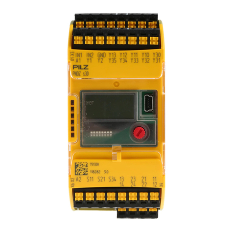
Pilz PNOZ s30 User manual
Other Pilz Relay manuals
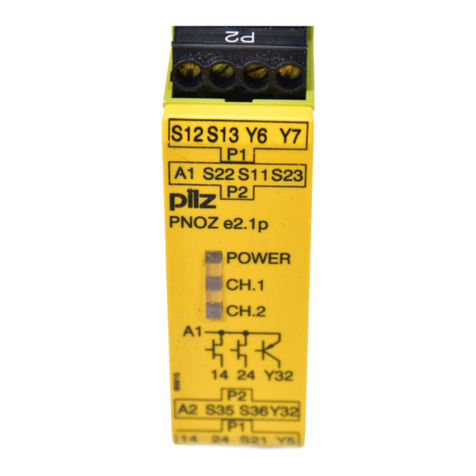
Pilz
Pilz PNOZELOG Series User manual
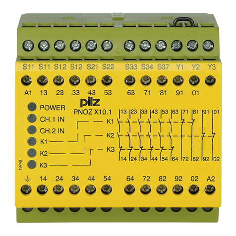
Pilz
Pilz PNOZ X10.1 User manual
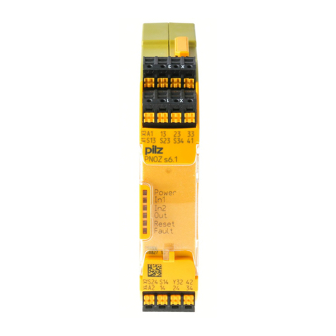
Pilz
Pilz PNOZ s6 User manual

Pilz
Pilz PNOZ X3P User manual

Pilz
Pilz PNOZ pe1p User manual
Pilz
Pilz PSEN im1 User manual
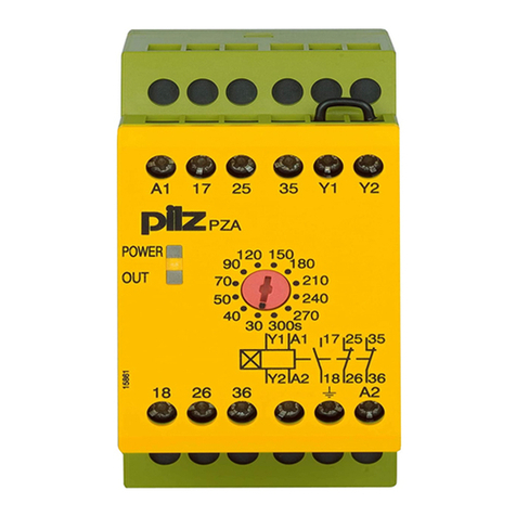
Pilz
Pilz PNOZ X Series User manual
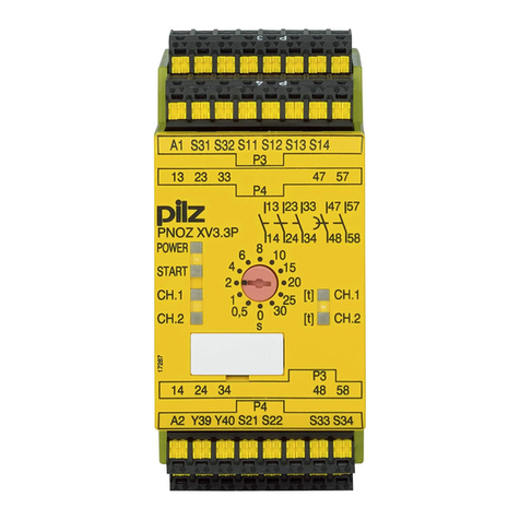
Pilz
Pilz PNOZ XV3.3P User manual

Pilz
Pilz PMD s10 User manual
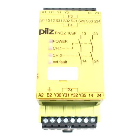
Pilz
Pilz PNOZ 16SP User manual

Pilz
Pilz PNOZ e8.1p User manual

Pilz
Pilz PNOZ X1P User manual

Pilz
Pilz 21398-6NL-06 User manual

Pilz
Pilz PNOZ s2 User manual
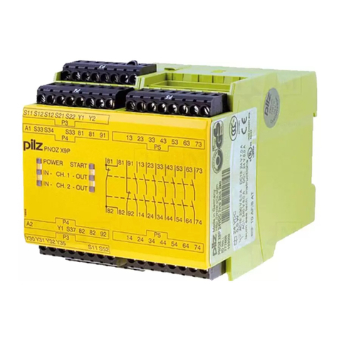
Pilz
Pilz PNOZ X9P AC/DC User manual
Pilz
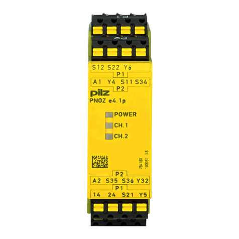
Pilz PNOZ e4.1p User manual
Pilz
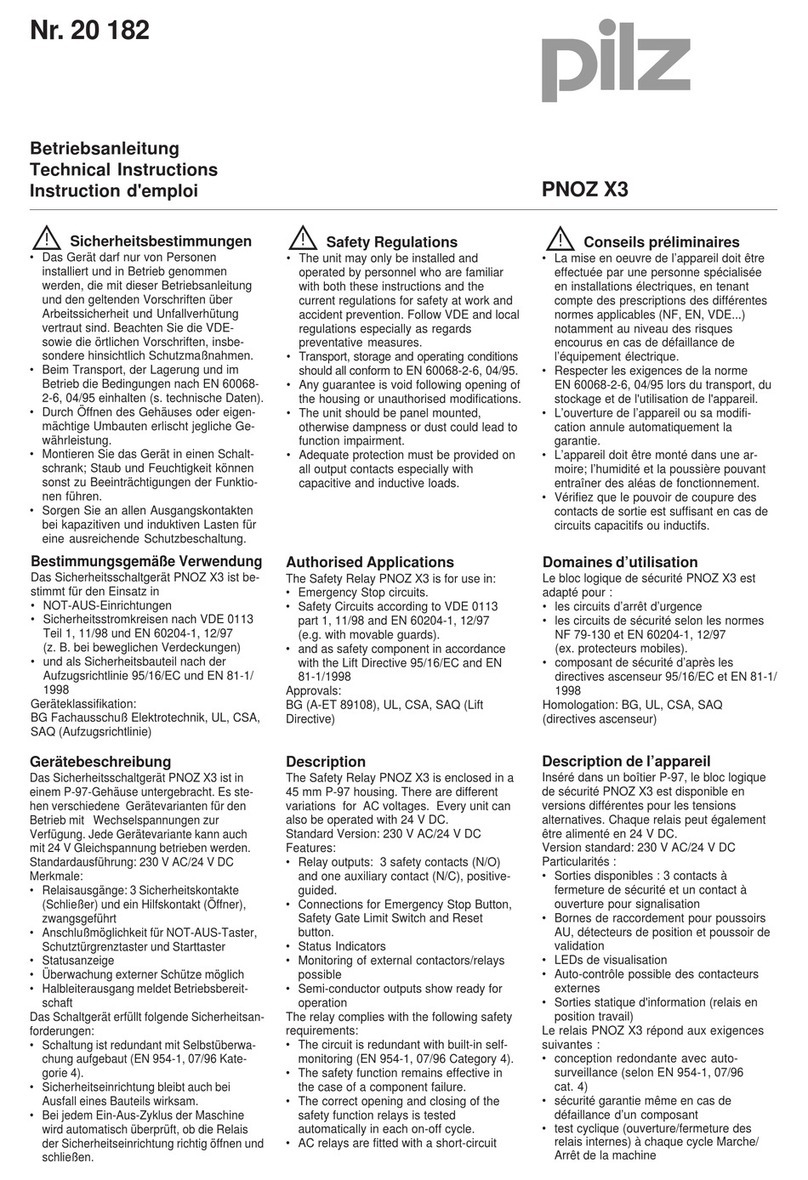
Pilz PNOZ X3 Owner's manual

Pilz
Pilz PNOZ pps1p User manual
Pilz
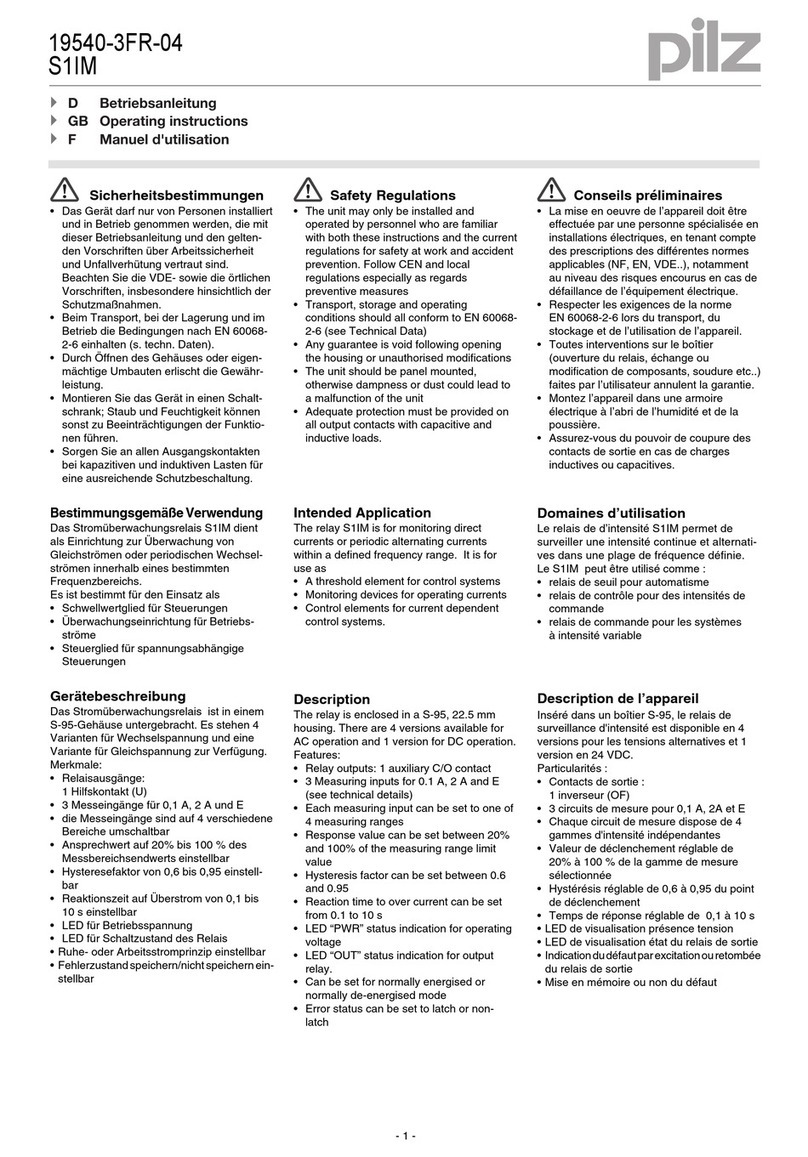
Pilz S1IM 19540-3FR-04 User manual
Pilz
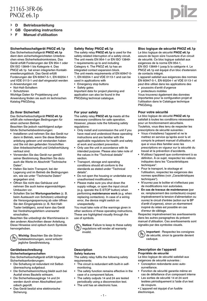
Pilz 21165-3FR-06 User manual
Popular Relay manuals by other brands

CD Automation
CD Automation REVEX 2PH 280A user manual

ABB
ABB SPAJ 142 C User manual and technical description

Ruelco
Ruelco 1S04 Operation manual

Basler
Basler V3E Z1P B2C1F instruction manual

Doepke
Doepke Dupline DSM 2 operating instructions

Siemens
Siemens SIRIUS 3RT1966-4D Original operating instructions
