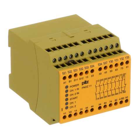
Pilz PNOZ XE2 User manual

20 077
Sicherheitsbestimmungen
• Das Gerät darf nur von einer Elektrofach-
kraft oder unterwiesenen Personen
installiert und in Betrieb genommen
werden, die mit dieser Betriebsanleitung
und den geltenden Vorschriften über
Arbeitssicherheit und Unfallverhütung
vertraut sind. Beachten Sie die VDE-
sowie die örtlichen Vorschriften, insbeson-
dere hinsichtlich Schutzmaßnahmen.
• Halten Sie beim Transport, der Lagerung
und im Betrieb die Bedingungen nach
EN 60068-2-6, 04/95 ein (s. techn. Daten).
• Entsorgen Sie das Gerät nach Ablauf
seiner Lebensdauer sachgerecht.
• Durch Öffnen des Gehäuses oder
eigenmächtige Umbauten erlischt jegliche
Gewährleistung.
• Bauen Sie das Gerät in einen Schalt-
schrank mit der Schutzklasse IP 54 ein.
• Sorgen Sie an allen Ausgangskontakten
bei kapazitiven und induktiven Lasten für
eine ausreichende Schutzbeschaltung.
• Diese Bedienungsanleitung dient der
Instruktion. Bewahren Sie sie für künftige
Verwendung auf.
Bestimmungsgemäße Verwendung
Das Erweiterungsgerät PNOZ XE2 darf nur
mit dem modularen Sicherheitsschaltgerät
PNOZ XM1 verwendet werden. Es stellt zwei
zusätzliche Eingangskreise zur Verfügung.
PNOZ XE2 ist bestimmt für den Einsatz in
• NOT-AUS-Einrichtungen
• Sicherheitsstromkreisen nach EN
60204-1, 12/97 (VDE 0113-1, 11/98)
(z. B. bei beweglichen Verdeckungen)
• Schutztüren mit 2 Verriegelungen und
3 Grenztastern
- nach EN 422, 06/95 bei Blasform-
maschinen, Schutzeinrichtung Typ III
- nach EN 201, 06/85 bei Spritzgieß-
maschinen
• Berührungslos wirkenden Schutzeinrich-
tungen (BWS) Typ 4 nach EN 61496-1,
06/98
Geräteklassifikationen:
BG Fachausschuß Elektrotechnik beantragt
Gerätebeschreibung
Das Erweiterungsgerät PNOZ XE2 ist in
einem S-95-Schmalbau-Gehäuse unter-
gebracht. Die Versorgungsspannung liefert
das PNOZ XM1.
Merkmale:
• 1 Eingangskreis für NOT-AUS-Taster oder
Schutztürgrenztaster und Verriegelungen
mit bis zu 3 Grenztastern
• 1 Eingangskreis für BWS mit Halbleiter-
ausgängen
• automatische Erkennung der angeschlos-
senen Schaltertypen
• LED-Statusanzeige
PNOZ XE2
Betriebsanleitung
Operating Instructions
Notice d'utilisation
Safety regulations
• The unit may only be installed and
operated by personnel who are familiar
with both these instructions and the
current regulations for safety at work and
accident prevention. Follow CEN and local
regulations especially as regards
preventive measures.
• Transport, storage and operating
conditions should all conform to
EN 60068-2-6, 04/95.
• Any guarantee will be rendered invalid if
the housing is opened or unauthorised
modifications are carried out.
• The unit must be disposed of properly
when it reaches the end of its service life.
• The unit should be panel mounted, other-
wise dampness or dust could lead to
function impairment.
• Adequate protection must be provided on
all output contacts with capacitive and
inductive loads.
• These operating instructions are intended
for instruction and should be retained for
future reference.
Intended use
The PNOZ XE2 input module may only be
used with the PNOZ XM1 safety relay. It
provides two additional input circuits.
PNOZ XE2 is intended for use in
• Emergency stop equipment
• Safety circuits in accordance with EN
60204-1, 12/97 (VDE 0113-1, 11/98)
(e.g. with moveable guards )
• Safety gates with 2 shot bolts and
3 limit switches
- in accordance with EN 422, 06/95 for
blow-moulding machinery, protection
equipment Type III
- in accordance with EN 201, 06/85 for
injection-moulding machinery
• Electrosensitive protection equipment
(ESPE) Type 4 in accordance with EN
61496-1, 06/98
Unit classification:
BG pending
Unit description
The PNOZ XE2 input module is enclosed in
an S-95 slimline housing. The PNOZ XM1
supplies the supply voltage for the unit.
Features:
• 1 input circuit for emergency stop button,
or safety gate switches and shot bolts with
with up to 3 limit switches
• 1 input circuit for ESPE with
semiconductor outputs
• The type of device connected is detected
automatically
• LEDs
Conseilspréliminaires
• La mise en oeuvre de l’appareil doit être
effectuée par un électricien ou une
personne spécialisée en installations
électriques, en tenant compte des
prescriptions des différentes normes
applicables (NF, EN, VDE...), notamment
au niveau des risques encourus en cas de
défaillance de l’équipement électrique.
• Respecter les exigences de la norme
EN 60068-2-6, 04/95 lors du transport, du
stockage et de l’utilisation de l’appareil.
• A la fin de sa durée de service, éliminez
l’appareil conformément aux prescriptions.
• L’ouverture du boîtier annule automatique-
ment la clause de garantie.
• Installez le relais dans une armoire
électrique de classe de protection IP 54.
• Assurez-vous du pouvoir de coupure des
contacts de sortie en cas de charges
inductives ou capacitives.
• Le manuel d’utilisation sert à l’instruction.
Veuillez conserver ce manuel pour une
utilisation ultérieure.
Domaine d’utilisation
L’appareil d’extension PNOZ XE2 ne doit
être utilisé qu’avec le relais de sécurité
modulaire PNOZ XM1. Il dispose de deux
circuits d’entrées supplémentaires.
Le PNOZ XE2 est spécialement conçu pour :
• les circuits d’arrêt d’urgence
• les circuits de sécurité selon les normes
EN 60204-1, 12/97 (VDE 0113-1, 11/98)
(ex. protecteurs mobiles)
• les protecteurs mobiles à 2 verrous et
3 interrupteurs de position
- selon EN 422, 06/95 pour les machines
de moulage par soufflage, dispositif de
protection type III
- selon EN 201, 06/85 pour les presses à
injecter
• les équipements de protection électro-
sensibles (EPS) de type 4 selon
EN 61496-1,06/98
Homologations :
BG Fachausschuß Elektrotechnik en cours
Description de l’appareil
L’appareil d’extension PNOZ XE2 est inséré
dans un boîtier S-95. Il est alimenté par le
PNOZ XM1.
Caractéristiques :
• 1 circuit d’entrée pour poussoir AU ou
interrupteur de position de protecteur
mobile et verrous avec un max. de 3
interrupteurs de position
• 1 circuit d’entrée pour EPS à sorties
statiques
• Détection automatique du mode de
câblage
• LEDs de visualisation
AUDIN
Composants & systèmes d'automatisme
7 bis rue de Tinqueux - 51100 Reims - France
Tel. +33(0)326042021 • Fax +33(0)326042820
http://www.audin.fr • e-mail info@audin.fr

• Schnittstelle zum Anschluß des
PNOZ XM1, PNOZ XE1 bzw. weiterer
PNOZ XE2
Das Erweiterungsgerät erfüllt folgende
Sicherheitsanforderungen:
• Schaltung ist redundant mit Selbstüberwa-
chung aufgebaut.
• Sicherheitseinrichtung bleibt auch bei
Ausfall eines Bauteils wirksam.
Funktionsbeschreibung
Das PNOZ XE2 erweitert das PNOZ XM1
um zwei Eingangskreise. Es dürfen max.
9 Erweiterungsgeräte (PNOZ XE1 oder
PNOZ XE2) an ein PNOZ XM1 angeschlos-
sen werden. Die Auswertung der Eingangs-
zustände übernimmt das PNOZ XM1.
Funktionen der LEDs:
• "POWER" leuchtet, wenn
Spannungsversorgung in Ordnung
• "Y14/24"
- leuchtet grün, wenn BWS-Ausgänge
aktiv
- blinkt gelb, wenn BWS-Ausgänge
inaktiv
- blinkt rot bei Fehler
• "S42/S52/S62"
- leuchtet grün, wenn Eingangskreis
geschlossen
- blinkt gelb, wenn Eingangskreis offen
- blinkt grün, wenn Eingangskreis
geschlossen. Für Anlauftest Eingangs-
kreis öffnen und wieder schließen.
- blinkt rot bei Fehler
Die Fehlerart ist in der Bedienungsanleitung
PNOZ XM1 beschrieben.
Betriebsarten:
• Einkanaliger Betrieb an den Eingangs-
kreisen: Eingangsbeschaltung nach
EN 60204-1, 12/97 (VDE 0113-1), keine
Redundanz im Eingangskreis,
Erdschlüsse im Tasterkreis werden
erkannt.
• Zweikanaliger Betrieb an den Eingangs-
kreisen: Redundanter Eingangskreis,
Erdschlüsse im Tasterkreis und Quer-
schlüsse zwischen den Tasterkontakten
werden erkannt.
• Dreikanaliger Betrieb an den Eingangs-
kreisen: Redundanter Eingangskreis,
Erdschlüsse im Tasterkreis und Quer-
schlüsse zwischen den Tasterkontakten
werden erkannt.
Fig. 1: Schematisches Schaltbild/
Internal diagram/
Schéma interne
• Interface to connect a
PNOZ XM1, PNOZ XE1 or additional
PNOZ XE2 devices
The input module fulfils the following safety
requirements:
• Circuit is redundant with built-in self-
monitoring
• Safety function remains effective if a
component fails.
Function description
The PNOZ XE2 input module is used to add
an extra 2 input circuits to the PNOZ XM1. A
maximum of 9 input modules can be
connected (PNOZ XE1 or PNOZ XE2 input
modules) to a PNOZ XM1. The status is
monitored and evaluated by the PNOZ XM1.
LED functions:
• “POWER” is lit if the supply voltage is
applied
• “Y14/24”
- is green if the ESPE outputs are active,
- flashes yellow, if the ESPE outputs are
not active
- flashes red if an error has occurred
• "S42/S52/S62"
- is green if the input circuit is closed
- flashes yellow if the input circuit is open
- flashes green if the input circuit is
closed.
For start-up test: open input circuit and
close again.
- flashes red if an error has cocurred
The types of error are described in the
PNOZ XM1 operating manual.
Operating modes:
• Single-channel operation at the input
circuits: input wiring in accordance with
EN 60204-1, 12/97 (VDE 0113-1), no
reduncdancy in the input circuit, earth
faults in the emergency stop circuit are
detected.
• Dual-channel operation at the input
circuits: redundant input circuit, earth
faults in the emergency stop circuit are
detected and short circuits across the
input channels.
• Triple-channel operation at the input
circuits: redundant input circuit, earth
faults in the emergency stop circuit are
detected and short circuits across the
input channels.
• Interface pour le branchement du
PNOZ XM1, PNOZ XE1 ou d’autres
PNOZ XE2
L’appareil d’extension répond aux exigences
suivantes :
• conception redondante avec auto-contrôle
• fonction de sécurité garantie même en cas
de défaillance d’un composant électroni-
que.
Description du fonctionnement
Le PNOZ XE2 ajoute deux circuits d’entrée
au PNOZ XM1. Vous pouvez brancher au
max. 9 appareils d’extension (PNOZ XE1
ou PNOZ XE2) sur un PNOZ XM1.
Le PNOZ XM1 se charge de l’exploitation
des états d’entrée.
Fonctions des LEDs :
• "POWER" est allumée, quandl’alimentation
est présente
• "Y14/24"
- est allumée (verte) quand les sorties
EPS sont actives
- clignote (jaune) quand les sorties EPS
sont inactives
- clignote (rouge) en cas d’erreur
• "S42/S52/S62"
- est allumée (verte) quand le circuit
d’entrée est fermé
- clignote (jaune) quand le circuit
d’entrée est ouvert
- clignote (verte) quand le circuit d’entrée
est fermé. Pour le test de démarrage,
ouvrir puis refermer le circuit d’entrée.
- clignote (rouge) en cas d’erreur
Les types d’erreurs sont décrits dans la
notice d’utilisation du PNOZ XM1.
Modes de fonctionnement :
• Monocanal : conforme aux prescriptions
de la norme EN 60204-1, 12/97
(VDE 0113-1), pas de redondance dans
le circuit d’entrée, la mise à la terre du
circuit d’entrée est détectée.
• 2 canaux d’entrée : circuit d’entrée
redondant.
La mise à la terre et les court-circuits entre
les contacts sont détectés.
• 3 canaux d’entrée : circuit d’entrée
redondant.
La mise à la terre et les court-circuits entre
les contacts sont détectés.
Y13 Y14Y23 S42 S52 S62
Eingänge/Inputs/Entrés
Y24
Schnittstelle PNOZ XE1/PNOZ XE2/PNOZ XM1
Interface PNOZ XE1/PNOZ XE2/PNOZ XM1
Schnittstelle PNOZ XE1/PNOZ XE2/Abschlußstecker
Interface PNOZ XE1/PNOZ XE2/Terminator
Interface PNOZ XE1/PNOZ XE2/Terminaison
Schieberegister/
Shift register/
Registre
Schieberegister/
Shift register/
Registre

Fig. 3: PNOZ XM1 und Erweiterungsgeräte mit Steckbrücken verbinden, auf letztes
Erweiterungsgerät Abschlußstecker stecken/
Connect the PNOZ XM1 and the input modules with the link, plug the terminator into the last
input module/
Raccordement du PNOZ XM1 et de l'appareil d’extension par le pont enfichable, mise en
place de la prise de terminaison sur le dernier appareil d’extension.
Fig. 2: Abschlußstecker abziehen/
Pull out the terminator/
Enlèvement de la prise de terminaison
Montage
Auf der Geräterückseite des PNOZ XM1
befindet sich 1 Stecker, auf der Rückseite
des Erweiterungsgeräts befinden sich
2 Stecker. Verbinden Sie das PNOZ XE2
über die mitgelieferte Steckbrücke mit dem
PNOZ XM1 und dem Eweiterungsgerät:
• Ziehen Sie den Abschlußstecker des
PNOZ XM1 ab (Fig. 2).
• Setzen Sie das PNOZ XE2 rechts neben
das PNOZ XM1 und stecken Sie die
Steckbrücke.
• Verbinden Sie bis zu 9 Erweiterungsgeräte
auf die gleiche Weise (Fig. 3). Die
Kombination von PNOZ XE1 und
PNOZ XE 2 ist beliebig.
• Stecken Sie auf den rechten Stecker des
letzten Erweiterungsgeräts die Steck-
brücke, die Sie vom PNOZ XM1 abgezo-
gen haben (Fig. 3).
Bauen Sie das Sicherheitsschaltgerät in
einen Schaltschrank mit einer Schutzart von
mindestens IP 54 ein. Das Gerät läßt sich
auf eine Normschiene aufschnappen.
Sichern sie das Gerät bei Montage auf einer
senkrechten Tragschiene (35 mm) durch ein
Halteelement wie z. B. Endhalter oder
Endwinkel.
Inbetriebnahme
Beachten Sie bei der Inbetriebnahme:
• Eingangskreis für BWS
Leitungslänge: durch BWS
festgelegt
• Eingangskreis für Sicherheitsschalter
Max. Leitungslängen: 3,5 km
Voraussetzungen:
Leiterquerschnitt: 1,5 mm2
Kapazität: 150 nF/km
Widerstand: 28 Ohm/km
Temperatur: +25 °C
• Leitungsmaterial aus Kupferdraht mit einer
Temperaturbeständigkeit von
60/75 °C verwenden.
• Das Anzugsdrehmoment der Schrauben
darf max. 0,6 Nm betragen.
• Angaben im Kapitel "Technische Daten"
unbedingt einhalten.
Ablauf:
• Gerät wie in Kapitel "Montage" beschrie-
ben verbinden.
Installation
There is one socket on the rear of the PNOZ
XM1 and two sockets on the back of the
input module. Connect the PNOZ XE2 and
the PNOZ XM1 using the link supplied with
the device :
• Pull out the terminator from the PNOZ
XM1 (Fig. 2).
• Place the PNOZ XE2 to the right of the
PNOZ XM1 and connect the two devices
using the link supplied
• A maximum of 9 input modules can be
connected using the same method (Fig.
3). You can have any combination of
PNOZ XE1 and XE2 devices up to a
maximum of 9 units.
• Insert the terminator you removed from
the PNOZ XM1 into the right-hand socket
of the last input module (Fig. 3).
The safety relay should be panel mounted
(min. IP 54). The unit can be mounted on to
a DIN-Rail. If the unit is installed on a
vertical mounting rail (35 mm), ensure the
device is secured using a fixing bracket such
as an end bracket or an end angle.
Operation
Please note:
• Input circuit for ESPE
Cable length: determined via
ESPE
• Input circuit for safety switch
Max. cable run 3.5 km
Requirements:
Cable cross section: 1.5 mm2
Capacity: 150 nF/km
Resistance: 28 Ohm/km
Temperature: +25 °C
• Use copper wiring that can withstand
temperatures of 60/75 °C.
• Tighten terminals to a max. 0.6 Nm
• Information given in “Technical Details”
should be observed.
To operate:
• Connect the unit as described in the
section “Installation”.
Montage
A l’arrière du PNOZ XM1 se trouve 1 con-
necteur, à l’arrière de l’appareil d’extension
2 connecteurs. Raccordez le PNOZ XE2 sur
le PNOZ XM1 et l’appareil d’extension à
l’aide du pont enfichable fourni :
• Retirez la prise de terminaison du
PNOZ XM1 (Fig. 2).
• Placez le PNOZ XE2 à droite du
PNOZ XM1 puis branchez le pont
enfichable.
• Raccordez de cette manière les autres
appareils d’extension(max. 9) (Fig. 3).
Vous pouvez librement associer des
PNOZ XE1 et PNOZ XE2.
• Branchez sur le connecteur droit du
dernier appareil d’extension le pont
enfichable que vous avez retiré du
PNOZ XM1 (Fig. 3).
Montez le relais de sécurité dans une
armoire électrique ayant au moins un indice
de protection IP 54. L’appareil peut être
encliqueté sur un rail DIN. En cas de
montage sur un profilé support vertical
(35 mm), fixez l’appareil à l’aide d’un
élément de retenue comme par ex. une
console ou une équerre terminale.
Mise en oeuvre
Remarques préliminaires :
• circuit d’entrée pour EPS
longueur de câblage : défini par
l’EPS
• circuit d’entrée pour organes de sécurité
longueur maxi câblage : 3,5 km
Conditions :
section câble : 1,5 mm2
capacité : 150 nF/km
résistivité : 28 Ohm/km
température : +25 °C
• Utiliser uniquement des fils de câblage en
cuivre 60/75 °C.
• Le couple de serrage ne doit pas dépasser
0,6 Nm.
• Respectez les données indiquées dans les
caractéristiques techniques.
Mise en oeuvre :
• Comme décrit dans "Montage".

S62
S31
S42
S21
S52
S11
S1 S2
S4
S62
S51
S42
S1
S62
S41
S52
S1
S52
S51
S62
S41
S42
S1
S2
S52
S31
S42
S21
S62
S1
S2
S11
S62
S1
S11
S52
S21
S42
S1
S11
S52
S21
S42
S1
S2
Faults - Disturbances
See PNOZ XM1 operating instructions.
Fig. 8: Schutztürsteuerung einkanalig mit
Anlauftestung/Single-channel safety gate
control with start-up test/Surveillance de
protecteur avec 1 interrupteur de position à
2 contacts et test des conditions initiales
Fig. 9: Schutztür mit 3 Positionsschaltern/
Safety gate with 3 position switches/
Surveillance de protecteur avec 3 contacts
de position
Fig. 7: Schutztürsteuerung einkanalig mit
Stellungsüberwachung/Single-channel
safety gate control with position monitoring/
Surveillance de protecteur avec 1
interrupteur de position à 2 contacts
Fig. 11: Schutztürsteuerung zweikanalig
mit Anlauftestung/Dual-channel safety gate
control with start-up test/Surveillance de
protecteur avec 2 interrupteurs de position
à 2 contacts avec test des conditions
initiales
Fig. 10: Schutztürsteuerung zweikanalig mit
Stellungsüberwachung/Dual-channel safety
gate control with position monitoring/
Surveillance de protecteuravec 2
interrupteurs de position à 2 contacts
Fig. 5: NOT-AUS zweikanalig/Dual-channel
E-Stop/Circuit AUen 2 canaux
Fig. 4: NOT-AUS einkanalig/Single-channel
E-Stop/Circuit AU en mono-canal Fig. 6: Schutztürsteuerung zweikanalig/
Dual-channel safety gate control/
Surveillance de protecteurs avec 2
interrupteurs de position
Erreur- Défaillance
Voir manuel d'utilisation PNOZ XM1.
Tür geschlossen/Gate closed/
porte fermée
Tür nicht geschlossen/Gate
open/porte ouverte
betätigtes Element/Switch
activated/élément actionné S1/S2/S4: NOT-AUS- bzw. Schutztür-
schalter/Emergency stop button
or safety gate switch/
Poussoir AU, détecteurs de
position
Fig. 12: BWS-Anschaltung/ESPE-interface/
Connexion EPS
• Eingangskreise
Beschalten Sie die Eingangskreise wie in
Fig. 4 ... 12 dargestellt
HINWEIS!
Wenn Sie nur den BWS-Eingangskreis
verwenden, Klemme S62 des unbenutz-
ten Eingangskreises mit Ausgang S11
verbinden.
Fehler - Störungen
S. Betriebsanleitung PNOZ XM1
• Input circuits
Input circuits should be wired as shown in
Fig. 4 ... 12
NOTE!
If you use the ESPE-input circuit, S62
of the input circuit not used must be
connected to S11.
S21
Y13
S11
Y23
Y14 Y24
BWS
OSSD1
OSSD2
BWS/ESPE/
EPS
• Circuits d’entrée
Branchez les circuits d’entrée comme sur
les Fig. 4 ... 12
INDICATION
Si vous n’utilisez que le circuit d’entrée
EPS, reliez la borne S62 du circuit
d’entrée inutilisé à la sortie S11.

Technische Daten/Technical Details/Caractéristiques techniques
Versorgungsspannung UB/Operating voltage/Tension d'alimentation UBvon/from/du PNOZ XM1
Leistungsaufnahme bei UB/Power consumption/Consommation pour UBca./approx./env.2 W
Eingangskreise/Input circuits/Circuit d'entrée 2
Spannung und Strom an/Voltage and current at/Tension, courant aux bornes
Y13, Y23 24 V DC/0,5 mA
Y14, Y24 16 ... 30 V DC/max. 10 mA
Min. BWS-Ausschaltimpuls/Minimum ESPE switch-off pulse/Impulsion min. de déconnexion
EPS 18 ms
Max. BWS-Ausgangstestimpuls/Maximum ESPE output test pulse/Impulsion-test max. de
sortie EPS 400 µs
Ausschaltverzögerung nach BWS-Ausgang inaktiv/
max. 10 ms + Rückfallverzögerung PNOZ XM1
Switch off delay once ESPE output inactive/
max. 10 ms + delay-on de-energisation
Temps de déconnexion si sortie EPS inactive
PNOZ XM1
max. 10 ms + temps de retombée PNOZ XM1
Einschaltverzögerung nach BWS-Ausgang aktiv/
max. 300 ms + Anzugsverzögerung PNOZ XM1
Switch-on delay once ESPE delay active/
max. 300 ms + delay-on energisation
Temps de montée si sortie EPS active
PNOZ XM1
max. 300 ms + temps de montée PNOZ XM1
Spannung und Strom an/Voltage and current at/Tension, courant aux bornes
S42, S52, S62 24 V DC/8 mA
Umgebungstemperatur/Operating temperature/Température de fonctionnement 0 ... +60 °C
Lagertemperatur/Storage temperature/Température de stockage 25 ... +70 °C
EMV/EMC/CEM EN 50081-1, 01/92, EN 50082-2, 03/95
Schwingungen nach/Vibrations to/Vibrations d'après EN 60068-2-6, 04/95 Frequenz/Frequency/Frequence: 10 ... 57 Hz
Amplitude/Amplitude/Amplitude: 0,075 mm
Klimabeanspruchung/Climate suitability/Conditions climatiques IEC 60068-2-3,1969
Anschlußklemmen: max. Querschnitt des Außenleiters/Max. cable cross section/ Einzelleiter oder mehrdrähtiger Leiter mit
Bornes de raccordement : capacité de raccordement Aderendhülsen/single and multi-core with
crimp connectors/conducteur unique ou
multi-conducteur avec embout : 1,5 mm2
Anzugsdrehmoment für Anschlußklemmen (Schrauben)Ttorque setting for connection terminal
0,6 Nm
screws/
couple de serrage (bornier)
Schutzart/Protection/Degré de protection
Einbauraum/Mounting (min.)/lieu d'installation IP 54
Gehäuse/Housing/Boîtier IP 40
Klemmen/Terminals/bornes IP 20
Gehäusematerial/Housing material/Matériau boîtier Kunststoff/Plastic/Plastique
Thermoplast Noryl SE 100
Abmessungen H x B x T/Dimensions H x D x W/Dimensions H x P x L 94 x 27 x 122 mm (3.7" x 1.06" x 4.8")
Gewicht/Weight/Poids 120 g
Abmessungen in mm (")/Dimensions in mm (")/Dimensions in mm (")
122 (4.8")
75 (2.95")
22,5
(0.89")
94 (3.7")
27
(1.06")

20 077-03/00 Printed in Germany
A
AUS
Pilz Australia, ✆(03) 95 44 63 00, Fax (03) 95 44 63 11, E-Mail:
B, L
BR
Pilz do Brasil Sistemas Eletrônicos, ✆(11) 43 37-12
CH
DK
E
Pilz Industrieelektronik S.L., ✆ (93) 8 49 74 33, Fax (93) 8 49 75 44, E-
Mail: [email protected]
F
FIN
Pilz Skandinavien KS, ✆(09) 27 09
37 00,
GB
I
IRL
Pilz Ireland Industrial Automation, ✆ (0 21) 27 48 83, Fax (0 21) 27 48 94,
J
MEX
Pilz de Mexico S. de R.L. de C.V., ✆(0
NL
P
PRC
Pilz China Representative Office, ✆(0 20) 87 37 16 18,
S
SGP
USA
Pilz LP, ✆ (2 48) 4 73-11 33, Fax (2 48) 4 73-39 97,
www
http://www.pilz.com
D
Stammhaus/Headquarter/Maison mère: Pilz GmbH & Co., Felix-Wankel-Straße 2, 73760 Ostfildern, ✆(07
11) 34
09-0, Fax (07
11) 34
09-1
33

Norme di sicurezza
• Il dispositivo deve essere installato e
messo in funzione solo da elettricisti o
persone addestrate a conoscenza delle
presenti istruzioni per l’uso e delle norme
antinfortunistiche e di sicurezza del lavoro
vigenti. Si devono inoltre rispettare le
norme VDE, nonché le norme locali,
soprattutto per quanto riguarda gli aspetti
della sicurezza.
• Per il trasporto, l’immagazzinamento e
l’esercizio, rispettare le norme
EN 60068-2-6, 04/95 (vedere i dati
tecnici).
• Smaltire il dispositivo secondo le
prescrizioni vigenti.
• In caso di apertura della custodia o di
modifiche non autorizzate, non sarà
riconosciuta alcuna garanzia.
• Montare il dispositivo in un armadio
elettrico con la classe di protezione IP 54.
• In caso di carichi capacitivi ed induttivi,
assicurare un’adeguata protezione per
tutti i contatti di uscita.
• Le istruzioni per l’uso devono essere
conservate accuratamente in modo da
poterle consultare per l’impiego futuro.
20 077
Disposiciones de seguridad
• El dispositivo debe ser instalado y puesto
en funcionamiento solo por un electro-
instalador o personas, que tengan
experiencia con estas Instrucciones de
uso y con las normativas vigentes de
seguridad del trabajo y prevención de
accidentes. Tenga en cuenta las
normativas VDE, como también las
normativas locales, especialmente en lo
concerniente a medidas de protección.
• Respetar las exigencias de la norma
EN 60068-2-6, 04/95 referente al
transporte, almacenaje y utilización del
dispositivo (v. datos técnicos).
• Deshágase del dispositivo de forma
apropiada, una vez concluida su vida útil.
• La apertura de la carcasa o manipulación
indebida en el dispositivo anula cualquier
tipo de garantía.
• Monte el dispositivo en un armario de
distribución con clase de protección
IP 54.
• Todos los contactos de salida sometidos a
cargas capacitivas e inductivas deben
estar convenientemente protegidos.
• Las Instrucciones de uso sirven para la
instrucción. Consérvelas para utilizaciones
futuras.
Campo de aplicación
El dispositivo de ampliación PNOZ XE2 se
debe utilizar solamente con el relé modular
de seguridad PNOZ XM 1. Éste pone
adicionalmente a disposición dos circuitos de
entrada. El PNOZ XE2 está determinado
para el empleo en
• equipos de PARO DE EMERGENCIA
• Circuitos eléctricos de seguridad según
EN 60204-1, 12/97 (VDE 0113-1, 11/98)
(por ej. para puertas protectoras móviles)
• Puertas protectoras con 2 bloqueos y
3 micros
- según EN 422, 06/95 en máquinas de
moldeo a presión, equipo de protección
tipo III
- según EN 201, 06/85 en máquinas de
moldeo por inyección
• Dispositivos de protección de acción sin
contacto (BWS) tipo 4 según EN 61496-1,
06/98
Clasificación de los dispositivos:
Solicitado BG de la comisión de expertos en
electrotecnia
Descripción del dispositivo
El dispositivo de ampliación PNOZ XE2 está
colocado en una carcasa de caja estrecha
S-95. El PNOXZ XM1 suministra la tensión
de alimentación.
Características:
• 1 circuito de entrada para pulsador de
PARO DE EMERGENCIA o micros de
PNOZ XE2
Instrucciones de uso
Istruzioni per l’uso
Gebruiksaanwijzing
Veiligheidsvoorschriften
• Het apparaat mag uitsluitend worden
geïnstalleerd en in bedrijf genomen door
een elektrotechnicus of een persoon die
vertrouwd is met deze gebruiksaanwijzing
en met de geldende voorschriften op het
gebied van arbeidsveiligheid en
ongevallenpreventie. Neemt u de van
toepassing zijnde Europese richtlijnen en
de plaatselijke voorschriften in acht, in het
bijzonder m.b.t. veiligheidsmaatregelen.
• Neemt u bij transport, opslag en in bedrijf
de richtlijnen volgens EN 60068-2-6, 04/95
in acht (zie technische gegevens).
• Verwijdert u na afloop van de levensduur
van het apparaat alle afvalstoffen op een
juiste manier.
• Het openen van de behuizing of het
eigenmachtig veranderen van de
schakeling heeft verlies van de garantie
tot gevolg.
• Monteert u het apparaat in een schakel-
kast met beschermingsgraad IP 54.
• Zorgt u bij capacitieve of inductieve
belasting van de uitgangscontacten voor
adequate contactbeschermings-
maatregelen.
• Deze gebruiksaanwijzing geeft instructies.
Ze dient voor toekomstig gebruik bewaard
te worden.
Toegelaten applicaties
Het uitbreidingsrelais PNOZ XE2 mag
uitsluitend worden gebruikt met het
modulaire veiligheidsrelais PNOZ XM1. Het
stelt twee extra ingangscircuits ter
beschikking. PNOZ XE2 is bestemd voor
• noodstopvoorzieningen
• veiligheidscircuits volgens EN 60204-1,
12/97 (VDE 0113-1, 11/98)
(b.v. bij beweegbare afschermingen)
• hekbewaking met 2 vergrendelingen en 3
deurcontacten
- volgens EN 422, 06/95 bij blaasvorm-
machines, afscherming type III
- volgens EN 201, 06/85 bij spuitgiet-
machines
• contactloos werkende veiligheidsvoor-
zieningen (ESPE: electrosensitive
protective equipment) type 4 volgens
EN 61496-1, 06/98
Goedkeuringen:
Aangevraagd bij BG Fachausschuß Elektro-
technik
Apparaatbeschrijving
Het uitbreidingsrelais PNOZ XE2 is in een
smalle S-95-behuizing ondergebracht. De
voedingsspanning wordt geleverd door de
PNOZ XM1. Kenmerken:
• 1 ingangscircuit voor noodstopknop of
deurcontact en vergrendelingen met max.
3 deurcontacten
Uso previsto
Il dispositivo di ampliamento PNOZ XE2
deve essere usato solo insieme al
dispositivo base di sicurezza PNOZ XM1
e mette a disposizione due ulteriori circuiti
di ingresso.
PNOZ XE2 è previsto per l’impiego in
• dispositivi di arresto di emergenza
• circuiti elettrici di sicurezza secondo
EN 60204-1, 12/97 (VDE 0113-1, 11/98)
(per es. per ripari mobili)
• porta di sicurezza con 2 o 3 fine corsa
- secondo EN 422, 06/95 per acchine di
formatura per soffiaggio, dispositivo
di protezione tipo III
- secondo EN 201, 06/85 per macchine
per iniezione
• barriere fotoelettriche (BWS) livello
4 secondo EN 61496-1, 06/98
Classificazione del dispositivo:
BG comitato tecnico elettrotecnico richiesto
Descrizione del dispositivo
Il dispositivo di ampliamento PNOZ XE2 è
inserito in custodia stretta S-95. La tensione
di alimentazione viene fornita da PNOZ
XM1.
Caratteristiche:
• 1 circuito di ingresso per pulsante di
arresto di emergenza o fine corsa per

puerta protectora y bloqueos con hasta
3 micros
• 1 circuito de entrada para BWS con
salidas El PNOZ XM1 se encarga de la
evaluación de los estados de entrada
• identificación automática de los tipos de
interruptores conectados
• Indicadores LED de estado
• Interface para la conexión del
PNOZ XM1, PNOZ XE1 u otro PNOZ XE2
El dispositivo de ampliación cumple los
siguientes requisitos de seguridad:
• Concepción redundante con autovigilancia
• El equipo de seguridad permanece activo
aún cuando falle un componente.
Características funcionales
El PNOZ XE2 amplía el PNOZ XM1 en dos
circuitos de entrada. Se pueden conectar
como máx. 9 dispositivos de ampliación
(PNOZ XE1 o PNOZ XE2) a un PNOZ XM1.
El PNOZ XM1 se encarga de la evaluación
de los estados de entrada.
Funciones de los LEDs:
• "POWER" está encendido cuando la
alimentación de tensión está en orden
• "Y14/24"
- está encendido en verde cuando las
salidas de BWS están activas
- parpadea en amarillo cuando las salidas
de BWS están inactivas
- parpadea en rojo cuando hay fallos
• "S42/S52/S62"
- está encendido en verde cuando el
circuito de entrada está cerrado
- parpadea en amarillo cuando el circuito
de entrada está abierto
- parpadea en verde cuando el circuito de
entrada está cerrado.
Para el test de rearme abrir y volver a
cerrar el circuito de entrada.
- parpadea en rojo cuando hay fallos
El tipo de error está descrito en las
instrucciones de uso del PNOZ XM1.
Modos de funcionamiento:
• Funcionamiento monocanal en los
Fig. 1: Esquema de conexiones/Schema di
collegamento/Intern schema
ripari mobili con max 3 fine corsa
• 1 circuito di ingresso per BWS con uscite
statiche
• rilevamento automatico dei tipi di
dispositivi collegati
• LED indicatori
• connettore per il collegamento di
PNOZ XM1, PNOZ XE1 o altri PNOZ XE2
Il modulo di ampliamento è conforme ai
seguenti requisiti di sicurezza:
• Concezione ridondante con autocontrollo
• Il dispositivo mantiene la sua funzione di
sicurezza anche in caso di avaria di un
componente.
• 1 ingangscircuit voor ESPE met
halfgeleideruitgangen
• Automatische detectie van de aangesloten
schakelaartypen
• Status-LED’s
• Communicatiepoort voor de aansluiting
van de PNOZ XM1, PNOZ XE1 of andere
PNOZ XE2
Het uitbreidingsrelais voldoet aan de
volgende veiligheidseisen:
• De schakeling is redundant met
zelfcontrole opgebouwd.
• Ook bij uitvallen van een component blijft
de veiligheidsschakeling werken.
Descrizione del funzionamento
Il PNOZ XE2 amplia il PNOZ XM1 di due
circuiti di ingresso. Si possono collegare
max. 9 dispositivi di ampliamento
(PNOZ XE1 o PNOZ XE2) ad un PNOZ
XM1. La verifica dello stato degli ingressi
viene effettuata dal PNOZ XM1.
Funzioni dei LED:
• "POWER" è acceso quando la tensione di
alimentazione è corretta
• "Y14/24"
- si accende a luce verde quando le
uscite BWS sono attive
- lampeggia a luce gialla quando le uscite
BWS sono inattive
- lampeggia a luce rossa in caso di errore
• "S42/S52/S62"
- si accende a luce verde quando il
circuito di ingresso è chiuso
- lampeggia a luce gialla quando il
circuito di ingresso è aperto
- lampeggia a luce verde quando il
circuito di ingresso è chiuso. Per il test
di avviamento aprire e chiudere
nuovamente il circuito di ingresso.
- lampeggia a luce rossa in caso di errore
Il tipo di errore è descritto nelle istruzioni per
l’uso PNOZ XM1.
Modalità operative:
• Funzionamento monocanale sui circuiti di
Functiebeschrijving
De PNOZ XE2 breidt de PNOZ XM1 met
twee ingangscircuits uit. Er mogen max.
9 uitbreidingsrelais (PNOZ XE1 of PNOZ
XE2) op een PNOZ XM1 aangesloten
worden. De ingangstoestanden worden door
de PNOZ XM1 geëvalueerd.
Functies van de LED’s
• „POWER“ licht op, als voedingsspanning
in orde is
• „Y14/24“
- licht groen op, als de ESPE-uitgangen
actief zijn
- licht geel op, als de ESPE-uitgangen
actief zijn
- licht rood op bij fouten
• „S42/S52/S62“
- licht groen op, als ingangscircuit
gesloten is
- licht geel op, als ingangscircuit open is
- licht groen op, als ingangscircuit
gesloten is. Voor aanlooptest
ingangscircuit openen en weer sluiten
- licht rood op bij fouten
De foutsoort is in de gebruiksaanwijzing
PNOZ XM1 beschreven.
Y13 Y14Y23 S42 S52 S62
Entradas/Ingressi/Ingangen
Y24
Interface con PNOZ XM1 y con el dispositivo de ampliación
Interfaccia con PNOZ XM1 e con il dispositivo di ampliamento
Poort naar PNOZ XM1 en uitbreidingsrelais
Inerface con el dispositivo de ampliación y con el conector final
Interfaccia con il dispositivo di ampliamento e con il connettore
di terminazione
Poort naar uitbreidingsrelais en afsluitconnector
Registro de desplazamiento/
Registro a scorrimento/
Schuifregister
Registro de desplazamiento/
Registro a scorrimento/
Schuifregister
Bedrijfsmodi
• Eenkanalig bedrijf van de ingangscircuits:

Fig. 3: Conectar el PNOZ XM1 y el dispositivo de ampliación con conectores puentes, en el
último dispositivo de ampliación enchufar un conector final/
Collegare il PNOZ XM1 ed i dispositivi di ampliamento con i connettori, collegare il connettore
di terminazione all’ultimo dispositivo di ampliamento/
PNOZ XM1 en uitbreidingsrelais met busconnectoren verbinden, op laatste uitbreidingsrelais
afsluitconnector steken
Fig. 2: Extraer el conector final/
Staccare il connettore di terminazione/
Afsluitconnector uittrekken
circuitos de entrada: Conexionado de
entrada según EN 60204-1, 12/97 (VDE
0113-1), sin redundancia en el circuito
de entrada, se detectan los defectos a
tierra en el circuito del pulsador.
• Funcionamiento bicanal en los circuitos
de entrada: Circuito de entrada
redundante, se detectan los defectos a
tierra en el circuito del pulsador y los
cortocircuitos entre los contactos del
pulsador.
• Funcionamiento tricanal en los circuitos
de entrada: Circuito de entrada
redundante, se detectan los defectos a
tiersra en el circuito del pulsador y los
cortocircuitos entre los contactos del
pulsador.
ingresso: Cablaggio in ingresso secondo
EN 60204-1, 12/97 (VDE 0113-1), senza
ridondanza nel circuito di ingresso;
i guasti a terra nel circuito del pulsante
vengono rilevati.
• Funzionamento bicanale sui circuiti di
ingresso: Circuito di ingresso ridondante;
vengono rilevati i guasti a terra nel circuito
del pulsante, nonché i cortocircuiti tra i
contatti del pulsante stesso.
• Funzionamento a tre canali sui circuiti di
ingresso: Circuito di ingresso ridondante;
vengono rilevati i guasti a terra nel circuito
del pulsante, nonché i cortocircuiti tra i
contatti del pulsante stesso.
ingangsschakeling volgens
EN 60204-1, 12/97 (VDE 0113-1), geen
redundantie in het ingangscircuit,
aardsluitingen in het ingangscircuit worden
gedetecteerd.
• Tweekanalig bedrijf van de ingangs-
circuits: redundant ingangscircuit,
aardsluitingen in het ingangscircuit en
onderlinge sluitingen tussen de
ingangscontacten worden gedetecteerd.
• Driekanalig bedrijf van de ingangscircuits:
redundant ingangscircuit, aardsluitingen in
het ingangscircuit en onderlinge sluitingen
tussen de ingangscontacten worden
gedetecteerd.
Montage
Op de achterzijde van de PNOZ XM1 bevindt
er zich 1 connector, op de achterzijde van het
uitbreidingsrelais bevinden zich
2 connectoren. Verbind de PNOZ XE2 via de
meegeleverde busconnector met de PNOZ
XM1 en het uitbreidingsrelais:
• Trek de afsluitconnector uit de PNOZ XM1
(fig. 2).
• Plaats de PNOZ XE2 rechts naast de
PNOZ XM1 en breng de busconnector
aan.
• Verbind maximaal 9 uitbreidingsrelais op
dezelfde manier (fig. 3). De combinatie
van PNOZ XE1 en PNOZ XE2 is
willekeurig.
• Steek op de rechter connector van het
laatste uitbreidingsrelais de busconnector
die u uit de PNOZ XM1 getrokken heeft
(fig. 3).
Bouw het veiligheidsrelais in een schakelkast
in met een beschermingsgraad van minimaal
IP 54. Het relais kan op een DIN-rail geklikt
worden. Bij montage op een verticale
draagrail (35 mm) moet het apparaat
worden vastgezet met een eindsteun.
Montaggio
Sul retro del dispositivo PNOZ XM1 si trova
1 connettore, mentre sul retro del modulo di
ampliamento si trovano 2 connettori.
Collegare il PNOZ XE2, mediante il
connettore ad innesto in dotazione, con
il PNOZ XM1 :
• Staccare il connettore di terminazione del
PNOZ XM1 (fig. 2).
• Posizionare il PNOZ XE2 a destra del
PNOZ XM1 ed innestare il connettore.
• Collegare in modo identico fino a max.
9 dispositivi di ampliamento (fig. 3).
E’ possibile combinare PNOZ XE1 e
PNOZ XE 2.
• Innestare sul connettore destro dell’ultimo
dispositivo di ampliamento il connettore di
terminazione staccato dal PNOZ XM1
(fig. 3).
Installare il dispositivo di sicurezza in un
armadio elettrico con un tipo di protezione di
almeno IP 54. Il dispositivo può essere
innestato su una guida DIN.
In caso di montaggio su una guida verticale
(35 mm), bloccare il dispositivo con un
elemento di fissaggio, per es. un supporto
terminale o una staffa angolare terminale.
Montaje
En la parte posterior del dispositivo
PNOZ XM1 se encuentra un conector 1,
en la parte posterior del dispositivo de
ampliación se encuentran 2 conectores.
Conecte el PNOZ XE2, mediante el puente
conector suministrado, con el PNOZ XM1 y
al dispositivo de ampliación:
• Extraiga la el conector final del PNOZ
XM1 (Fig. 2).
• Coloque el PNOZ XE2 a la derecha junto
al PNOZ XM1 y enchufe el conector
puente.
• Conecte hasta 9 dispositivos de
ampliación de igual modo (Fig. 3). La
combinación de PNOZ XE1 y PNOZ
XE 2 es arbitraria.
• Enchufe en el conector derecho del último
dispositivo de ampliación el conector
puente, que Ud. ha extraído del XM1 (Fig.
3).
Monte el relé de seguridad en un armario de
distribución con un grado de protección de
por lo menos IP 54. El dispositivo se puede
fijar a presión en una guía normalizada.
Asegure el dispositivo en el montaje sobre
una guía de sujeción (35 mm) vertical
mediante un elemento de fijación como por
ej. con un soporte.

S62
S31
S42
S21
S52
S11
S1 S2
S4
S62
S51
S42
S1
S62
S41
S52
S1
S11
S62
S1
S11
S52
S21
S42
S1
S11
S52
S21
S42
S1
S2
Fig. 8: Supervisión de puerta protectora
monocanal con comprobación de rearme/
Comando monocanale riparo mobile con
test di avviamento/Eenkanalige
hekbewaking met aanlooptest
Fig. 9: Puerta protectora con 3 interruptores
de posición/Riparo mobile con 3 interruttori
di posizione/Hekbewaking met 3 positie-
schakelaars
Fig. 7: Supervisión de puerta protectora
monocanal con supervisión de posición/
Comando monocanale riparo mobile con
monitoraggio posizione/Eenkanalige
hekbewaking met positiebewaking
Fig. 5: PARO DE EMERGENCIA bicanal/
Arresto di emergenza bicanale/
Tweekanalige noodstop
Fig. 4: PARO DE EMERGENCIA
monocanal/Arresto di emergenza
monocanale/Eenkanalige noodstop
Fig. 6: Supervisión de puerta protectora
bicanal/Comando bicanale riparo mobile/
Tweekanalige hekbewaking
Puesta en funcionamiento
En la puesta en funcionamiento tenga en
cuenta lo siguiente:
• Circuito de entrada para BWS
Longitud del cable: determinado
por el BWS
• Circuito de entrada para interruptor de de
seguridad
Longitudes máx. de cable: 3,5 km.
Requisitos:
Sección del cable: 1,5 mm 2
Capacidad: 150 nF/km.
Resistencia: 28 0hm/km
Temperatura: +25 °C
• Emplear solo conductores de cobre con
resistencia a temperatura de 60/75 °C.
• El par de apriete de los tornillos no debe
superar a 0,6 Nm.
• Es necesario tener en cuenta las indica-
ciones del capítulo "Datos Técnicos".
Proceso:
• Conectar el dispositivo como se describe
en el capítulo "Montaje".
• Circuitos de entrada
Conecte los circuitos de entrada como
están representados en la fig. 4 ... 12
¡ADVERTENCIA!
Si Ud. solamente utiliza el circuito de
enrada BWS, conecte el borne S62 del
circuito de entrada no utilizado con la
salida S11.
Messa in funzione
Per la messa in funzione rispettare quanto
segue:
• Circuito di ingresso per BWS
(barriera fotoelettrica)
Lunghezza cavi: determinata dal
BWS
• Circuito di ingresso per interruttore di
sicurezza (finecorsa)
Lunghezze max dei cavi: 3,5 km
Presupposti:
Sezione dei conduttori: 1,5 mm2
Capacità: 150 nF/km
Resistenza: 28 Ohm/km
Temperatura: +25 °C
• Usare cavi di rame con una resistenza
termica di 60/75 °C.
• La coppia di serraggio delle viti non deve
essere superiore a 0,6 Nm.
• Rispettare assolutamente le indicazioni
riportate nel capitolo "Dati tecnici".
Procedura:
• Collegare il dispositivo come descritto nel
capitolo "Montaggio".
• Circuiti di ingresso
Cablare i circuiti di ingresso come
illustrato in fig. 4 ... 12
NOTA BENE!
Se viene utilizzato solo nel circuito di
ingresso BWS, collegare il morsetto
S62 del circuito di ingresso non
utilizzato con l’uscita S11.
Errori - guasti
Vedere le istruzioni per l’uso PNOZ XM1.
Ingebruikname
Neem bij ingebruikname het volgende in
acht:
• Ingangscircuit voor ESPE
Kabellengte: door ESPE
bepaald
• Ingangscircuit voor veiligheidsschakelaar
Max. kabellengte: 3,5 km
Voorwaarden:
Kabeldoorsnede: 1,5 mm2
Capaciteit: 150 nF/km
Weerstand: 28 ohm/km
Temperatuur: +25 °C
• Kabelmateriaal uit koperdraad met een
temperatuurbestendigheid van
60/75 °C gebruiken.
• Het aanhaalmoment van de schroeven
mag max. 0,6 Nm bedragen.
• Aanwijzingen in het hoofdstuk “Technische
gegevens” beslist opvolgen.
Gebruik
• Relais verbinden zoals beschreven in het
hoofdstuk „Montage“.
• Ingangscircuits
Schakel de ingangscircuits zoals
voorgesteld in fig. 4 ... 12
AANWIJZING!
Als u alleen het ESPE-ingangscircuit
gebruikt, klem S62 van het ongebruikte
ingangscircuit met uitgang S11
verbinden.
Fouten - Storingen
Zie gebruiksaanwijzing PNOZ XM1
Defectos - Averías
Ver instrucciones de uso PNOZ XM1.

Datos técnicos/Dati tecnici/Technische gegevens
Tensión de alimentación UB/Tensione di alimentazione UB/Voedingsspanning UBdel/di/van PNOZ XM1
Consumo de potencia para UB/Potenza assorbita con UB/Opgenomen vermogen bij UBaprox./ca./ca. 2 W
Circuitos de entrada/Circuiti di ingresso/Ingangscircuits 2
Tensión y corriente en/Tensione e corrente a/Spanning en stroom op
Y13, Y23 24 V DC / 0,5 mA
Y14, Y24 16 ... 30 V DC / máx. 10 mA
Min. impulso de desconexión del BWS/Impulso di disinserimento BWS min./
Min. ESPE-uitschakelimpuls 18 ms
Máx. impulso test de desconexión del BWS/Impulso test uscita BWS max./
Max. ESPE-uitgangstestimpuls 400 µs
Retardo de desconexión según la salida del BWS inactivo/ máx. 10 ms + retardo a la desconexión del/
Ritardo di disattivazione dopo uscita BWS inattiva/ max. 10 ms + ritardo di sgancio/
Uitschakelvertraging na inactiviteit van ESPE-uitgang max.10 ms + afvalvertraging PNOZ XM1
Retardo de conexión según la salida del BWS activo/ máx. 300 ms + retardo a la conexión del/
Ritardo di attivazione dopo uscita BWS inattiva/ max. 300 ms + ritardo di eccitazione/
Inschakelvertraging na activiteit van ESPE-uitgang
max. 300 ms
+
opkomvertraging
PNOZ XM1
Tensión y corriente en/Tensione e corrente a/Spanning en stroom op
S42, S52, S62 24 V DC / 8 mA
Temperatura ambiental/Temperatura ambiente/Omgevingstemperatuur 0 ... +60 °C
Temperatura de almacenaje/Temperatura di immagazzinamento/Opslagtemperatuur 25 ... +70 °C
CEM/Compatibilità elettromagnetica/EMC EN 50081-1, 01/92, EN 50082-2, 03/95
Vibraciones según/Oscillazioni secondo/Trillingsbestendigheid volgens Frecuencia/Frequenza/Frequentie:
EN 60068-2-6, 04/95 10 ... 57 Hz
Amplitud/Ampiezza/Amplitude: 0,075 mm
Condiciones climáticas/Sollecitazione climatica/Klimaatcondities IEC 60068-2-3,1969
Bornes de conexión: Sección máx. del cable exterior/ Cable unifilar o multifilar con terminales/
Morsetti di collegamento: Sezione max. del conduttore esterno/ Conduttore singolo o conduttore a più fili
con capocorda/
Aansluitklemmen: max. doorsnede van de aansluitkabels Enkele of meerdere draden met
adereindhulzen : 1,5 mm 2
Par de apriete para los bornes de conexión (tornillos)/Coppia di serraggio per 0,6 Nm
morsetti di collegamento (viti)/Aanhaalmoment voor aansluitklemmen (schroeven)
Grado de protección/Protezione/Beschermingsgraad
Lugar de montaje/Vano di montaggio/Inbouwruimte IP 54
Carcasa/Custodia/Behuizing IP 40
Bornes/Morsetti/Klemmen IP 20
Material de la carcasa/Materiale custodia/Behuizingsmateriaal plástico/Resina termoplastica/Kunststof
Thermoplast Noryl SE 100
Dimensiones Altura x Ancho x Prof./Dimensioni a x l x p/Afmetingen H x B x D 94 x 27 x 122 mm (3.7" x 1.06" x 4.8")
Peso/Peso/Gewicht 120 g
Puerta cerrada/Riparo chiuso/
Hek gesloten
Puerta abierta/Riparo aperto/Hek
open
elemento accionado/Elemento
azionato/Bekrachtigd element S1/S2/S4: Interruptor de PARO DE
EMERGENCIA o de puerta
protectora/Pulsante di arresto
di emergenza o finecorsa riparo
mobile /Noodstop- of
hekschakelaar
S52
S51
S62
S41
S42
S1
S2
S52
S31
S42
S21
S62
S1
S2
S21
Y13
S11
Y23
Y14 Y24
BWS
OSSD1
OSSD2
Fig. 11: Control de puerta protectora
bicanal con comprobación de arranque/
Comando bicanale riparo mobile con test
di avviamento/Tweekanalige hekbewaking
met aanlooptest
Fig. 10: Supervisión de puerta protectora
bicanal con supervisión de posición/
Comando bicanale riparo mobile con
monitoraggio posizione/Tweekanalige
hekbewaking met positiebewaking
Fig. 12: Conexionado BWS/Collegamento
BWS/ESPE-aansluiting
BWS/
ESPE

20 077-03/00 Printed in Germany
Dimensiones en mm (")/Dimensioni in mm (")/Afmetingen in mm (")
122 (4.8")
75 (2.95")
22,5
(0.89")
94 (3.7")
27
(1.06")
Pilz Ges.m.b.H., (01) 7 98 62 63-0, Fax (01) 7 98 62 64, E-Mail: ilz@ ilz.at Pilz Australia, (03) 95 44 63 00, Fax (03) 95 44 63 11, E-Mail:
safety@ ilz.com.au Pilz Belgium, (0 53) 83 66 70, Fax (0 53) 83 89 58, E-Mail: info@ ilz.be Pilz do Brasil Sistemas Eletrônicos, (11) 43 37-12 41,
Fax (11) 43 37-12 42, E-Mail: ilz@ ilzbr.com.br Pilz Industrieelektronik GmbH, (0 62) 8 89 79 30, Fax (0 62) 8 89 79 40, E-Mail: ilz@ ilz.ch
Pilz Skandinavien KS, 74 43 63 32, Fax 74 43 63 42, E-Mail: ilz@ ilz.dk Pilz Industrieelektronik S.L., (93) 8 49 74 33, Fax (93) 8 49 75 44, E-Mail:
central@ ilzs ain.es Pilz France Electronic, 03 88 10 40 00, Fax 03 88 10 80 00, E-Mail: siege@ ilz-france.fr Pilz Skandinavien KS, (09) 27 09 37 00,
Fax (09) 27 09 37 09, E-Mail: [email protected] Pilz Automation Technology, (0 15 36) 46 07 66, Fax (0 15 36) 46 08 66, E-Mail: sales@ ilz.co.uk
Pilz Italia srl, (0 31) 78 95 11, Fax (0 31) 78 95 55, E-Mail: info@ ilz.it Pilz Ireland Industrial Automation, (0 21) 4 34 65 35, Fax (0 21) 4 80 49 94,
E-Mail: sales@ ilz.ie Pilz Ja an Co., Ltd., (0 45) 4 71-22 81, Fax (0 45) 4 71-22 83, E-Mail: ilz@ ilz.co.j Pilz de Mexico S. de R.L. de C.V., (0 13)
1 22 16 81, Fax (0 13) 6 47 81 85, E-Mail: [email protected] Pilz Nederland, (03 47) 32 04 77, Fax (03 47) 32 04 85, E-Mail: info@ ilz.nl
Pilz Industrieelektronik S.L., (21) 9 28 91 09, Fax (21) 9 28 91 13, E-Mail: ilz@esoterica. t Pilz China Re resentative Office, (0 20) 87 37 16 18,
Fax (0 20) 87 37 35 55, E-Mail: ilzchn@ ublic.guangzhou.gd.cn Pilz Korea Liaison Office, (31) 5 54 12 80, Fax (31) 5 54 12 80, E-Mail: [email protected]
Pilz Skandinavien KS, (03 00) 1 39 90, Fax (03 00) 3 07 40, E-Mail: ilz@tri net.se Pilz Industrial Automation Pte Ltd., 8 44 44 40, Fax 8 44 44 41,
E-Mail: sales@ ilz.com.sg Pilz LP, (7 34) 3 54-02 72, Fax (7 34) 3 54-33 55, E-Mail: info@ ilzusa.com htt ://www. ilz.com
Pilz GmbH & Co., Felix-Wankel-Straße 2, 73760 Ostfildern, Deutschland +49 (7 11) 34 09-0, Fax +49 (7 11) 34 09-1 33, E-Mail: ilz.gmbh@ ilz.de
Table of contents
Other Pilz Relay manuals

Pilz
Pilz PNOZ Ex Series User manual

Pilz
Pilz PNOZ 16SP User manual

Pilz
Pilz P1HZ X1 User manual

Pilz
Pilz PSWZ X1P User manual

Pilz
Pilz PNOZ X1 User manual

Pilz
Pilz PNOZ s4 User manual

Pilz
Pilz PNOZ pe2p User manual

Pilz
Pilz PNOZ X2.1C User manual

Pilz
Pilz PNOZ e4.1p User manual

Pilz
Pilz PSWZ X1P Owner's manual