Pilz PNOZ s6.1 User manual

PNOZ s6.1
Operating Manual-21692-EN-08
Safety relays

Preface
This document is the original document.
All rights to this documentation are reserved by Pilz GmbH & Co. KG. Copies may be made
for internal purposes. Suggestions and comments for improving this documentation will be
gratefully received.
Pilz®, PIT®, PMI®, PNOZ®, Primo®, PSEN®, PSS®, PVIS®, SafetyBUS p®, SafetyEYE®,
SafetyNET p®, the spirit of safety® are registered and protected trademarks of Pilz GmbH
& Co. KG in some countries.
SD means Secure Digital

PNOZ s6.1
Operating Manual PNOZ s6.1
21692-EN-08 3
Safety relay PNOZ s6.1
The safety relay can be used as a two-hand control relay or for simultaneity monitoring.
The safety relay meets the requirements of EN 60947-5-1, EN 60204-1 and VDE 0113-1
and may be used in applications with
}E-STOP pushbuttons
}Safety gates
The two-hand control relay meets the requirements of EN 574 Type IIIA. It forces the oper-
ator to keep his hands outside the danger zone area during the hazardous movement. It is
designed for use in two-hand circuits.
ATTENTION!
The two-hand control relay may not be used on press controllers. It is only
suitable for use where the risk analysis has established a low level of risk
(e.g. EN 954-1 Cat. 1 and EN ISO 13849-1 Cat. 1).
For your safety
}Only install and commission the unit if you have read and understood these operating
instructions and are familiar with the applicable regulations for health and safety at work
and accident prevention.
Ensure VDE and local regulations are met, especially those relating to safety.
}Any guarantee is rendered invalid if the housing is opened or unauthorised modifica-
tions are carried out.
}The supply voltage for the two-hand relay must only be connected after the shutdown
device in accordance with § 9 VBG 7n5.1/2.
}To avoid inductive and capacitance coupling, the cables between the two-hand relay
and the pushbuttons must be run separately to any power cables.
}On account of the low currents you should use gold-plated pushbutton contacts.
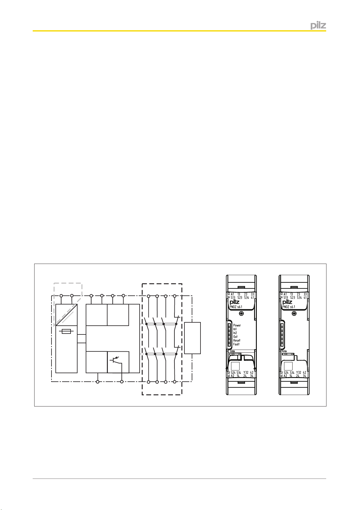
Unit features
}Positive-guided relay outputs:
– 3 safety contacts (N/O), instantaneous
– 1 auxiliary contact (N/C), instantaneous
}1 semiconductor output
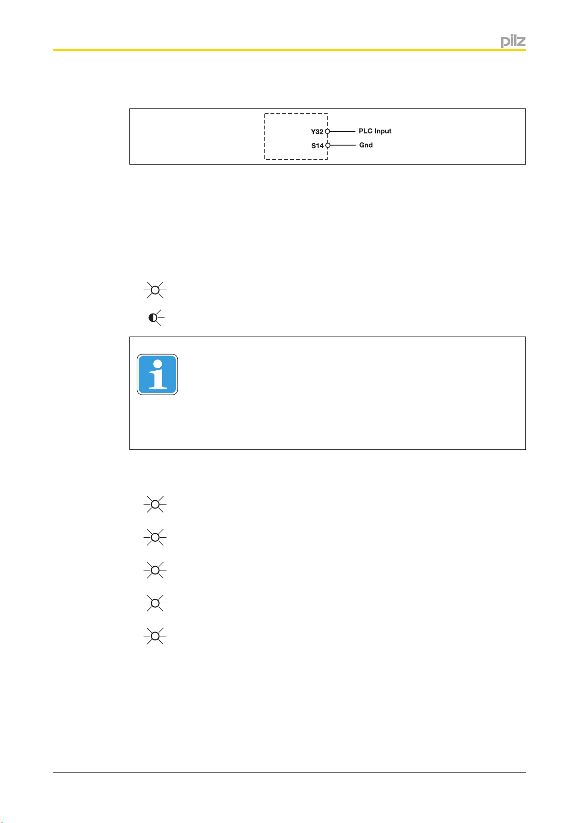
}Connection options for:
– 2 control elements (pushbuttons)
– Emergency stop pushbutton
– Safety gate limit switches
}A connector can be used to connect 1 PNOZsigma contact expansion module
}LED for:
– Supply voltage
– Input status, channel 1

PNOZ s6.1
Operating Manual PNOZ s6.1
21692-EN-08 4
– Input status, channel 2
– Switch status of the safety contacts
– Feedback loop
– Fault
}Plug-in connection terminals (either spring-loaded terminal or screw terminal)
Safety features
The safety relay meets the following safety requirements:
}The safety relay prevents the plant from being enabled in the following cases:
– Power supply failure
– Component failure
– Short circuit on an input circuit
– Coil defect
– Open circuit
– Earth fault
}In each on-off cycle, the output relays on the safety device are tested to ensure they
open and close correctly
}The unit has an electronic fuse.
Block diagram/terminal configuration
Centre: Front view with cover, right: Front view without cover
Grey highlighted area: Applies only with UB= 48 – 240 V AC/DC
*Insulation between the non-marked area and the relay contacts: Basic insulation (overvolt-
age category III), safe separation (overvoltage category II)

PNOZ s6.1
Operating Manual PNOZ s6.1
21692-EN-08 5
Function description
}The safety relay must be activated by simultaneously pressing two control elements
(pushbuttons) within 0,5 s . If one or both pushbuttons are released or the contacts
open, the unit interrupts the control command for the hazardous movement.
}Reactivation: The output relays will not re-energise until both control elements have
been released and re-operated simultaneously or the contacts have opened and then
closed.
Installation
Install base unit without contact expansion module:
}Ensure that the plug terminator is inserted at the side of the unit.
Connect base unit and PNOZsigma contact expansion module:
}Remove the plug terminator at the side of the base unit and at the contact expansion
module.
}Connect the base unit and the contact expansion module to the supplied connector be-
fore mounting the units to the DIN rail.
Installation in control cabinet
}The safety relay should be installed in a control cabinet with a protection type of at least
IP54.
}Use the notch on the rear of the unit to attach it to a DIN rail (35 mm).
}When installed vertically: Secure the unit by using a fixing element (e.g. retaining brack-
et or end angle).
}Push the device upwards or downwards before lifting it from the DIN rail.
Wiring
Please note:
}Information given in the "Technical details" must be followed.
}Outputs 13-14, 23-24, 33-34 are safety contacts; output 41-42 is an auxiliary contact
(e.g. for display).
}Auxiliary contact 41-42 and semiconductor output Y32 should not be used for safety
circuits!
}To prevent contact welding, a fuse should be connected before the output contacts (see
technical details).
}Calculation of the max. cable length lmax in the input circuit:
Rlmax = max. overall cable resistance (see technical details)
Rl/ km = cable resistance/km
}Use copper wire that can withstand 60/75 °C.
}Sufficient fuse protection must be provided on all output contacts with capacitive and in-
ductive loads.

PNOZ s6.1
Operating Manual PNOZ s6.1
21692-EN-08 6
Preparing for operation
}Supply voltage
Supply voltage AC DC
}Input circuit
Input circuit Single-channel Dual-channel
Two-hand pushbuttons
with detection of shorts
across contacts
Simultaneity monitoring in
safety gate applications
with automatic start after the
safety gate is closed
ATTENTION!
*The unit starts automatically when the E-STOP / safety gate device is re-
leased. Use external circuit measures to prevent an unexpected restart.
}Feedback loop
Feedback loop
Contacts from external con-
tactors

PNOZ s6.1
Operating Manual PNOZ s6.1
21692-EN-08 7
}Semiconductor output
Legend
}S1/S2: Two-hand pushbuttons
Operation
The unit is ready for operation when the Power LED is permanently lit.
LEDs indicate the status and errors during operation:
LED on
LED flashes
Information
Status indicators and error indicators may occur independently. In the case
of an error display, the "Fault" LED will light or flash (exception: "Supply
voltage too low"). An LED that is also flashing indicates the potential cause
of the error. An LED that is lit and is static indicates a normal operating sta-
tus. Several status indicators and error indicators may occur simultaneously.
Status indicators
Power
Supply voltage is present.
In1
Pushbutton at S13 is operated.
In2
Pushbutton at S23 is operated.
Out
Safety contacts are closed and semiconductor output Y32 carries a high signal.
Reset
24 V DC is present at S34.

PNOZ s6.1
Operating Manual PNOZ s6.1
21692-EN-08 8
Fault indicators
All LEDs off
Diagnostics: Short across contacts/earth fault; unit switched off
}Remedy: Rectify short across contacts/earth fault, switch off supply voltage
for 1 min.
Fault
Diagnostics: Plug terminator not connected
}Remedy: Insert plug terminator, switch supply voltage off and then on
again.
Fault
Diagnostics: Internal error, unit defective
}Remedy: Switch supply voltage off and then on again, change unit if neces-
sary.
Power
Diagnostics: Supply voltage too low
}Remedy: Check the supply voltage.
In1, In2 alternately
Fault
Diagnostics: Connection error or short between S124 and S24 detected or in-
ternal error
}Remedy: Rectify connection error or short across contacts, switch supply
voltage off and then on again.
In1
Fault
Diagnostics: Simultaneity exceeded: Channel 1 too late or power-up blocked
due to short-term interruption at S13; input circuits not operated simultaneously
}Remedy: Open both input circuits, S14 and S24, simultaneously and then
close again.
In2
Fault
Diagnostics: Simultaneity exceeded: Channel 2 too late or power-up blocked
due to short-term interruption at S23; input circuits not operated simultaneously
}Remedy: Open both input circuits, S14 and S24, simultaneously and then
close again.

PNOZ s6.1
Operating Manual PNOZ s6.1
21692-EN-08 9
Faults - malfunctions
}Contact malfunctions: If the contacts have welded, reactivation will not be possible after
the input circuit has opened.
Service life graph
The service life graphs indicate the number of cycles from which failures due to wear must
be expected. The wear is mainly caused by the electrical load; the mechanical load is negli-
gible.
UB24 VDC
Example
}Inductive load: 0,2 A
}Utilisation category: AC15
}Contact service life: 2,000,000 cycles
Provided the application requires fewer than 2,000,000 cycles, the PFH value (see techni-
cal details) can be used in the calculation.
To increase the service life, sufficient spark suppression must be provided on all output
contacts. With capacitive loads, any power surges that occur must be noted. With contac-
tors, use freewheel diodes for spark suppression.

PNOZ s6.1
Operating Manual PNOZ s6.1
21692-EN-08 10
UB48-240 VAC/DC
Example
}Inductive load: 0,2 A
}Utilisation category: AC15
}Contact service life: 1,000,000 cycles
Provided the application requires fewer than 1,000,000 cycles, the PFH value (see techni-
cal details) can be used in the calculation.
To increase the service life, sufficient spark suppression must be provided on all output
contacts. With capacitive loads, any power surges that occur must be noted. With contac-
tors, use freewheel diodes for spark suppression.

PNOZ s6.1
Operating Manual PNOZ s6.1
21692-EN-08 11
Technical details
General 750126 750156 751126 751156
Approvals CCC, CE, GOST,
KOSHA, TÜV, cU-
Lus Listed
CCC, CE, GOST,
KOSHA, TÜV, cU-
Lus Listed
CCC, CE, GOST,
KOSHA, TÜV, cU-
Lus Listed
CCC, CE, GOST,
KOSHA, TÜV, cU-
Lus Listed
Electrical data 750126 750156 751126 751156
Supply voltage
Voltage 24 V 48 - 240 V 24 V 48 - 240 V
Type DC AC/DC DC AC/DC
Voltage tolerance -15 %/+10 % -15 %/+10 % -15 %/+10 % -15 %/+10 %
Output of external
power supply
(AC)
–7,0 VA –7,0 VA
Output of external
power supply
(DC)
3,5 W 3,5 W 3,5 W 3,5 W
Frequency range
AC
–50 - 60 Hz –50 - 60 Hz
Residual ripple
DC
20 % 20 % 20 % 20 %
Continuous duty 100 % 100 % 100 % 100 %
Max. overall cable
resistance Rlmax
per input circuit
30 Ohm 30 Ohm 30 Ohm 30 Ohm
Voltage at
Input circuit DC 24,0 V 24,0 V 24,0 V 24,0 V
Feedback loop
DC
24,0 V 24,0 V 24,0 V 24,0 V
Current at
Feedback loop 15,0 mA 15,0 mA 15,0 mA 15,0 mA
N/O contact 20 mA 20 mA 20 mA 20 mA
Number of output
contacts
Instantaneous
safety contacts
(N/O)
3333
Auxiliary contacts
(N/C)
1111
Min. unit fuse protec-
tion
1,00 A 1,00 A 1,00 A 1,00 A
Max. unit fuse pro-
tection F1
Max. cable cross
section
Max. cable cross
section
Max. cable cross
section
Max. cable cross
section
Two-hand control re-
lay type
In accordance
with the standard
EN 574 EN 574 EN 574 EN 574
Type III A III A III A III A
Inputs 750126 750156 751126 751156
Number 2222

PNOZ s6.1
Operating Manual PNOZ s6.1
21692-EN-08 12
Semiconductor
outputs
750126 750156 751126 751156
Number 1111
Voltage 24,0 V 24,0 V 24,0 V 24,0 V
Current 20 mA 20 mA 20 mA 20 mA
Relay outputs 750126 750156 751126 751156
Max. short circuit
current IK
1 kA 1 kA 1 kA 1 kA
Utilisation category
In accordance
with the standard
EN 60947-4-1 EN 60947-4-1 EN 60947-4-1 EN 60947-4-1
Auxiliary contacts,
AC1 at
240 V 240 V 240 V 240 V
Min. current 0,01 A 0,01 A 0,01 A 0,01 A
Max. current 6,0 A 6,0 A 6,0 A 6,0 A
Max. power 1500 VA 1500 VA 1500 VA 1500 VA
Auxiliary contacts,
DC1 at
24 V 24 V 24 V 24 V
Min. current 0,01 A 0,01 A 0,01 A 0,01 A
Max. current 6,0 A 6,0 A 6,0 A 6,0 A
Max. power 150 W 150 W 150 W 150 W
Safety contacts,
AC1 at
240 V 240 V 240 V 240 V
Max. current 6,0 A 6,0 A 6,0 A 6,0 A
Min. current 0,01 A 0,01 A 0,01 A 0,01 A
Max. power 1500 VA 1500 VA 1500 VA 1500 VA
Safety contacts,
DC1 at
24 V 24 V 24 V 24 V
Max. current 6,0 A 6,0 A 6,0 A 6,0 A
Min. current 0,01 A 0,01 A 0,01 A 0,01 A
Max. power 150 W 150 W 150 W 150 W
Utilisation category
In accordance
with the standard
EN 60947-5-1 EN 60947-5-1 EN 60947-5-1 EN 60947-5-1
Auxiliary contacts,
AC15 at
230 V 230 V 230 V 230 V
Max. current 5,0 A 3,0 A 5,0 A 3,0 A
Auxiliary contacts,
DC13 (6 cycles/
min) at
24 V 24 V 24 V 24 V
Max. current 5,0 A 4,0 A 5,0 A 4,0 A
Safety contacts,
AC15 at
230 V 230 V 230 V 230 V
Max. current 5,0 A 3,0 A 5,0 A 3,0 A
Safety contacts,
DC13 (6 cycles/
min) at
24 V 24 V 24 V 24 V
Max. current 5,0 A 4,0 A 5,0 A 4,0 A

PNOZ s6.1
Operating Manual PNOZ s6.1
21692-EN-08 13
Relay outputs 750126 750156 751126 751156
Contact fuse protec-
tion, external safety
contacts
In accordance
with the standard
EN 60947-5-1 EN 60947-5-1 EN 60947-5-1 EN 60947-5-1
Blow-out fuse,
quick
10 A 6 A 10 A 6 A
Blow-out fuse,
slow
6 A 4 A 6 A 4 A
Circuit breaker,
24V AC/DC, char-
acteristic B/C
6 A 4 A 6 A 4 A
Contact fuse protec-
tion, external auxilia-
ry contacts
Blow-out fuse,
quick
10 A 6 A 10 A 6 A
Blow-out fuse,
slow
6 A 4 A 6 A 4 A
Circuit breaker,
24 V AC/DC,
characteristic B/C
6 A 4 A 6 A 4 A
Contact material AgCuNi + 0,2 µm
Au
AgCuNi + 0,2 µm
Au
AgCuNi + 0,2 µm
Au
AgCuNi + 0,2 µm
Au
Conventional ther-
mal current while
loading several
contacts
750126 750156 751126 751156
Ith per contact at UB
AC
Conv. therm. cur-
rent with 1 con-
tact
–6,00 A –6,00 A
Conv. therm. cur-
rent with 2 con-
tacts
–6,00 A –6,00 A
Conv. therm. cur-
rent with 3 con-
tacts
–4,50 A –4,50 A
Ith per contact at UB
DC
Conv. therm. cur-
rent with 1 con-
tact
6,00 A 6,00 A 6,00 A 6,00 A
Conv. therm. cur-
rent with 2 con-
tacts
6,00 A 6,00 A 6,00 A 6,00 A
Conv. therm. cur-
rent with 3 con-
tacts
6,00 A 4,50 A 6,00 A 4,50 A

PNOZ s6.1
Operating Manual PNOZ s6.1
21692-EN-08 14
Times 750126 750156 751126 751156
Delay-on de-energi-
sation (reaction time
in accordance with
EN 574)
N/O contact 40 ms 40 ms 40 ms 40 ms
N/C contact 50 ms 50 ms 50 ms 50 ms
Recovery time 250 ms 250 ms 250 ms 250 ms
Supply interruption
before de-energisa-
tion
20 ms 20 ms 20 ms 20 ms
Simultaneity, chan-
nel 1 and 2
0,5 s 0,5 s 0,5 s 0,5 s
Environmental data 750126 750156 751126 751156
Climatic suitability EN 60068-2-78 EN 60068-2-78 EN 60068-2-78 EN 60068-2-78
Ambient temperature
Temperature
range
-10 - 55 °C -10 - 55 °C -10 - 55 °C -10 - 55 °C
Storage temperature
Temperature
range
-40 - 85 °C -40 - 85 °C -40 - 85 °C -40 - 85 °C
EMC EN 60947-5-1, EN
61000-6-2, EN
61000-6-4
EN 60947-5-1, EN
61000-6-2, EN
61000-6-4
EN 60947-5-1, EN
61000-6-2, EN
61000-6-4
EN 60947-5-1, EN
61000-6-2, EN
61000-6-4
Vibration
In accordance
with the standard
EN 60068-2-6 EN 60068-2-6 EN 60068-2-6 EN 60068-2-6
Frequency 10,0 - 55,0 Hz 10,0 - 55,0 Hz 10,0 - 55,0 Hz 10,0 - 55,0 Hz
Max. amplitude 0,35 mm 0,35 mm 0,35 mm 0,35 mm
Airgap creepage
In accordance
with the standard
EN 60947-1 EN 60947-1 EN 60947-1 EN 60947-1
Overvoltage cate-
gory
III / II III / II III / II III / II
Pollution degree 2222
Rated insulation volt-
age
250 V 250 V 250 V 250 V
Rated impulse with-
stand voltage
4,00 kV 4,00 kV 4,00 kV 4,00 kV
Protection type
Mounting (e.g.
cabinet)
IP54 IP54 IP54 IP54
Housing IP40 IP40 IP40 IP40
Terminals IP20 IP20 IP20 IP20
Mechanical data 750126 750156 751126 751156
Mounting position Any Any Any Any
Mechanical life 10,000,000 cycles 10,000,000 cycles 10,000,000 cycles 10,000,000 cycles

PNOZ s6.1
Operating Manual PNOZ s6.1
21692-EN-08 15
Mechanical data 750126 750156 751126 751156
Material
Bottom PC PC PC PC
Front PC PC PC PC
Top PC PC PC PC
Cross section of ex-
ternal conductors
with screw terminals
1 core flexible 0,25 - 2,50 mm², 24
- 12 AWG
0,25 - 2,50 mm², 24
- 12 AWG
– –
2 core with the
same cross sec-
tion, flexible with
crimp connectors,
no plastic sleeve
0,25 - 1,00 mm², 24
- 16 AWG
0,25 - 1,00 mm², 24
- 16 AWG
– –
2 core with the
same cross sec-
tion, flexible with-
out crimp connec-
tors or with TWIN
crimp connectors
0,20 - 1,50 mm², 24
- 16 AWG
0,20 - 1,50 mm², 24
- 16 AWG
– –
Torque setting with
screw terminals
0,50 Nm 0,50 Nm – –
Connection type Screw terminal Screw terminal Spring-loaded ter-
minal
Spring-loaded ter-
minal
Mounting type plug in plug in plug in plug in
Cross section of ex-
ternal conductors
with spring-loaded
terminals: flexible
with/without crimp
connector
––0,20 - 2,50 mm², 24
- 12 AWG
0,20 - 2,50 mm², 24
- 12 AWG
Spring-loaded termi-
nals: Terminal points
per connection
––2 2
Stripping length – – 9 mm 9 mm
Dimensions
Height 98,0 mm 98,0 mm 100,0 mm 100,0 mm
Width 22,5 mm 22,5 mm 22,5 mm 22,5 mm
Depth 120,0 mm 120,0 mm 120,0 mm 120,0 mm
Weight 185 g 205 g 185 g 205 g
The standards current on 2011-06 apply.

PNOZ s6.1
Operating Manual PNOZ s6.1
21692-EN-08 16
Safety characteristic data
Operating
mode
EN ISO
13849-1:
2006
PL
EN ISO
13849-1:
2006
Category
EN IEC
62061
SIL CL
EN IEC
62061
PFHD[1/h]
IEC 61511
SIL
IEC 61511
PFD
EN ISO
13849-1:
2006
TM[year]
Emergency
stop/safety
gate function
PL e Cat. 4 SIL CL 3 2,62E-09 SIL 3 3,32E-05 20
Two-hand
function
PL c Cat. 1 SIL CL 1 5,99E-08 SIL 1 5,10E-03 20
All the units used within a safety function must be considered when calculating the safety
characteristic data.
Information
A safety function's SIL/PL values are not identical to the SIL/PL values of
the units that are used and may be different. We recommend that you use
the PAScal software tool to calculate the safety function's SIL/PL values.
ATTENTION!
It is essential to consider the relay's service life graphs. The relay outputs'
safety-related characteristic data is only valid if the values in the service life
graphs are met.
The PFH value depends on the switching frequency and the load on the relay output. If the
service life graphs are not accessible, the stated PFH value can be used irrespective of the
switching frequency and the load, as the PFH value already considers the relay's B10d val-
ue as well as the failure rates of the other components.
Order reference
Order reference
Product type Features Terminals
Order
no.
PNOZ s6.1 24 VDC Screw terminals 750 126
PNOZ s6.1 C 24 VDC Spring-loaded terminals 751 126
PNOZ s6.1 48 - 240 VAC/DC Screw terminals 750 156
PNOZ s6.1 C 48 - 240 VAC/DC Spring-loaded terminals 751 156

PNOZ s6.1
Operating Manual PNOZ s6.1
21692-EN-08 17
EC declaration of conformity
This product/these products meet the requirements of the directive 2006/42/EC for machin-
ery of the European Parliament and of the Council. The complete EC Declaration of Con-
formity is available on the Internet at www.pilz.com/downloads.
Representative: Norbert Fröhlich, Pilz GmbH & Co. KG, Felix-Wankel-Str. 2, 73760 Ostfil-
dern, Germany

...
Sachnummer Printed in Germany
© Pilz GmbH & Co. KG, 2011
+49 711 3409-444
Pilz GmbH & Co. KG
Felix-Wankel-Straße 2
73760 Ostfildern, Germany
Telephone: +49 711 3409-0
Telefax: +49 711 3409-133
E-Mail: [email protected]
Internet: www.pilz.com
Technical support
In many countries we are
represented by our subsidiaries
and sales partners.
Please refer to our homepage
for further details or contact our
headquarters.
InduraNET p®, Pilz®, PIT®, PMCprotego®, PMI®, PNOZ®, Primo®, PSEN®, PSS®, PVIS®, SafetyBUS p®, SafetyEYE®, SafetyNET p®, the spirit of safety®are registered and protected trademarks
of Pilz GmbH & Co. KG in some countries. We would point out that product features may vary from the details stated in this document, depending on the status at the time of publication and the scope
of the equipment. We accept no responsibility for the validity, accuracy and entirety of the text and graphics presented in this information. Please contact our Te chnical Support if you have any questions.
21692-EN-08, 2013-05 Printed in Germany
© Pilz GmbH & Co. KG, 2011
Back cover
Other manuals for PNOZ s6.1
1
Table of contents
Other Pilz Relay manuals

Pilz
Pilz PNOZ e5.11p User manual

Pilz
Pilz PNOZ s20 User manual

Pilz
Pilz S1EN User manual

Pilz
Pilz PNOZ s5 User manual

Pilz
Pilz PNOZ s1 User manual

Pilz
Pilz PNOZ e3.1p User manual

Pilz
Pilz PNOZ po3.3p User manual

Pilz
Pilz PNOZ X10.11P User manual

Pilz
Pilz S1UM/UP User manual

Pilz
Pilz PNOZSIGMA Series User manual