Pilz PNOZ e3vp 10 User manual

- 1 -
Sicherheitsschaltgerät PNOZ e3vp
Das Schaltgerät PNOZ e3vp dient dem
sicherheitsgerichteten Unterbrechen eines
Sicherheitsstromkreises. Das Gerät erfüllt
Forderungen der EN 954-1 oder
EN ISO 13849-1 bis Kategorie 4. Es darf
eingesetzt werden
• mit den Sicherheitsensoren
PSEN 2.1p-10 und PSEN 2.1p-11 in
Sicherheitsstromkreise nach EN 60947-5-
3, PDF-M
• als Auswertegerät für Positionsschalter mit
Öffner-/Schließer-Kombination
Wichtige Daten für Projektierung und
Anwendung finden Sie auch im technischen
Katalog PNOZelog.
21244-3FR-03
PNOZ e3vp 10, PNOZ e3vp 300
4D Betriebsanleitung
4GB Operating instructions
4F Manuel d'utilisation
Safety Relay PNOZ e3vp
The safety relay PNOZ e3vp is used for the
safety-related interruption of a safety circuit.
The unit meets requirements of EN 954-1 or
EN ISO 13849-1 up to category 4.
It may be used:
• With the safety switches PSEN 2.1p-10
and PSEN 2.1p-11 in safety circuits in
accordance with EN 60947-5-3, PDF-M
• As an evaluation device for position
switches with combination of N/C and N/O
Important data for project planning and
application can also be found in the
PNOZelog technical catalogue.
Bloc logique de sécurité PNOZ e3vp
Le bloc logique de sécurité PNOZ e3vp
assure de façon sûre l'ouverture d'un circuit
de sécurité. Ce bloc logique satisfait aux
exigences de la norme EN 954-1,
EN ISO 13849-1 jusqu’à la catégorie 4.
L'appareil peut être utilisé :
• avec les capteurs de sécurité
PSEN 2.1p-10 et PSEN 2.1p-11 dans les
circuits de sécurité d‘après EN 60947-5-3,
PDF-M
• comme relais de contrôle pour
interrupteurs de position avec un contact à
ouverture et un contact à fermeture
Vous trouverez également des données
importantes pour la configuration projet et
l’utilisation dans le Catalogue technique
PNOZelog.
Pour votre sécurité
Le bloc logique de sécurité PNOZ e3vp
satisfait à toutes les conditions nécessaires
pour un fonctionnement sécuritaire.
Toutefois, vous êtes tenu de respecter les
prescriptions de sécurité suivantes :
• Vous n’installerez l’appareil et ne le
mettrez en service qu’après avoir lu et
compris le présent manuel d’utilisation, et
que si vous êtes familier avec les
prescriptions en vigueur sur la sécurité du
travail et la prévention d’accidents.
• N'utilisez l'appareil que conformément à sa
définiton. A ce sujet, respectez les valeurs
indiquées dans les "Caractéristiques
techniques".
• Pour le transport, le stockage et
l'utilisation, respectez les exigences des
normes specifiées (voir „Caractéristiques
techniques“).
• N’ouvrez pas le boîtier et n'effectuez pas
de modifications non autorisées.
•En cas de travaux de maintenance (par
ex. remplacement des contacteurs) coupez
impérativement la tension d’alimentation ou
ouvrez le circuit d’entrée (action sur le BP
d’arrêt d’urgence), sinon un réarmement
inopiné du relais est possible en cas
d’erreur de câblage.
Respectez impérativement les avertissements
dans les autres paragraphes du présent
manuel d’utilisation. Ces avertissements sont
signalés par des symboles visuels.
Important : Respectez les consignes
de sécurité, sinon la garantie devient
caduque.
For your safety
The safety relay PNOZ e3vp meets all the
necessary conditions for safe operation.
However, please note the following safety
regulations:
• Only install and commission the unit if you
have read and understood these
instructions and are familiar with both
these instructions and the current
regulations for health and safety at work
and accident prevention.
• Only use the unit in accordance with its
intended purpose. Please also take note of
the values in the “Technical details”
section.
• Transport, storage and operating
conditions should all conform to the
standards as stated under “Technical
details”.
• Do not open the housing or undertake any
unauthorised modifications.
• Please make sure you shut down the
supply voltage, or open the input circuit
(e.g. operate the E-STOP button) when
performing maintenance work (e.g. when
replacing contactors). In case of a wiring
error, the device might switch on
unexpectedly.
You must take note of the warnings given in
other sections of these operating instructions.
These are highlighted visually through the
use of symbols.
Notice: Failure to keep to these safety
regulations will render all warranty
invalid.
Zu Ihrer Sicherheit
Das Sicherheitsschaltgerät PNOZ e3vp
erfüllt alle notwendigen Bedingungen für
einen sicheren Betrieb.
Beachten Sie jedoch nachfolgend aufge-
führte Sicherheitsbestimmungen:
• Installieren und nehmen Sie das Gerät nur
dann in Betrieb, wenn Sie diese Betriebs-
anleitung gelesen und verstanden haben
und Sie mit den geltenden Vorschriften
über Arbeitssicherheit und Unfallverhütung
vertraut sind.
• Verwenden Sie das Gerät nur gemäß
seiner Bestimmung. Beachten Sie dazu
auch die Werte im Abschnitt “Technische
Daten”.
• Halten Sie beim Transport, bei der
Lagerung und im Betrieb die Bedingungen
ein, wie sie unter "Technische Daten"
angegeben sind.
• Öffnen Sie nicht das Gehäuse und
nehmen Sie auch keine eigenmächtigen
Umbauten vor.
• Schalten Sie bei Wartungsarbeiten (z. B.
beim Austausch von Schützen) unbedingt
die Versorgungsspannung ab oder öffnen
Sie den Eingangskreis.
Beachten Sie unbedingt die Warnhinweise in
den anderen Abschnitten dieser Anleitung.
Diese Hinweise sind optisch durch Symbole
hervorgehoben.
Wichtig: Beachten Sie die Sicher-
heitsbestimmungen, sonst erlischt
jegliche Gewährleistung.

- 2 -
Gerätebeschreibung
Sicherheitseigenschaften
Das Schaltgerät erfüllt folgende Sicher-
heitsanforderungen:
• Die Schaltung ist redundant mit Selbst-
überwachung aufgebaut.
• Die Sicherheitseinrichtung bleibt auch bei
Ausfall eines Bauteils wirksam.
• Die Sicherheitsausgänge werden durch
einen Abschalttest periodisch geprüft.
• Das Gerät besitzt eine elektronische
Sicherung.
Gerätemerkmale
• Ausgänge in Halbleitertechnik:
2 Sicherheitsausgänge, wahlweise
unverzögert oder verzögert, 1 Hilfsaus-
gang und 2 Taktausgänge
• Anschlussmöglichkeit für
Sicherheitsensoren PSEN 2.1p-10 und
PSEN 2.1p-11 oder Positionsschalter mit
Öffner-/Schließer-Kombination
• Rückfallverzögerung einstellbar
• Hilfsausgang umschaltbar als Diagnose-
ausgang
• UND- und ODER-Eingang zur logischen
Verknüpfung mehrerer Geräte
• Querschlussüberwachung durch Takt-
ausgänge
• Statusanzeige
• Rückführkreis zur Überwachung externer
Schütze
Description de l’appareil
Propriétés de sécurité
Le bloc logique de sécurité satisfait aux
exigences de sécurité suivantes :
• Conception redondante avec auto-
surveillance.
• Fonction de sécurité garantie même en
cas de défaillance d'un composant interne
• Les sortie de sécurité sont testées
périodiquement à l'aide d'un test de
coupure.
• L'appareil est équipé d'un fusible
électronique.
Caractéristiques de l’appareil
• Sorties statiques : 2 sorties de sécurité, au
choix instantanées ou temporisées,
1 sortie d’information et 2 sorties
impulsionnelles
• Raccordement possible des capteurs de
sécurité PSEN 2.1p-10 et PSEN 2.1p-11
ou d’un interrupteur de position avec un
contact à ouverture et un contact à
fermeture
• Temporisation à la retombée réglable
• Sortie d'information commutable en sortie
de diagnostic
• Entrées ET et OU pour le couplage
logique de plusieurs appareils
• Surveillance des courts-circuits par sorties
impulsionnelles
• Affichage de l’état
• Boucle de retour pour le contrôle des
contacteurs externes
Descriptif du fonctionnement
Fonctionnement
Deux micro-processeurs analysent les
circuits d'entrée et pilotent en conséquence
les sorties. Les micro-processseurs se
contrôlent mutuellement.
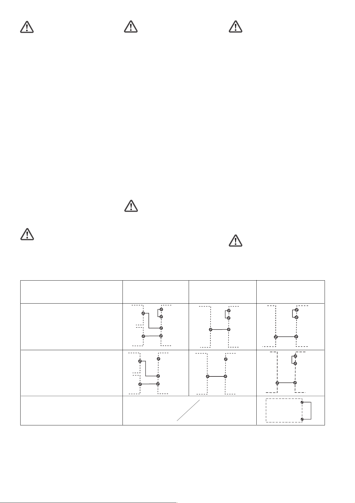
Etat des sorties
• Circuit d’entrée : contact à ouverture
ouvert et contact à fermeture fermé (par
ex. protecteur fermé).
Mise sous tension des sorties de sécurité
14 et 24 (temporisée) et de la sortie
d'information Y32.
• Circuit d’entrée : contact à ouveture fermé
et contact à fermeture ouvert (par ex.
protecteur ouvert).
Blocage des sorties de sécurité 14 et 24
(temporisée) et de la sortie d'information
Y32.
Fonctions
• Si un signal Haut (+24 V CC) est appliqué
sur l’entrée Y5 pendant au moins 250 ms,
la sortie Y32 commute en sortie
diagnostic. Son exploitation est réalisée
via un protocole disponible en tant
qu'accessoire ou développé par
l'utilisateur. Si l’entrée Y5 est ouverte ou
Bas, Y32 fonctionne comme une sortie
d'information.
• Pour le couplage logique de plusieurs
appareils, le PNOZ e3vp possède une
entrée ET et une entrée OU. Les entrées
ont une temporisation de couplage qui est
cumulative dans le cas d’une liaison ET.
• La sortie de sécurité 24 est une sortie
temporisée à la retombée. Dans le cas
où seule la fonction OU est utilisée, la
sortie de sécurité 14 peut elle aussi être
temporisée en retombée. Le temps de
retombée est réglable.
• En cas de défaut, une diminution de la
temporisation à la retombée est possible.
Description
Safety features
The relay fulfils the following safety
requirements:
• The circuit is redundant with built-in self-
monitoring.
• The safety function remains effective in the
case of a component failure.
• The safety outputs are tested periodically
using a disconnection test.
• The unit has an electronic fuse.
Unit features
• Outputs use semiconductor technology:
2 safety outputs,instantaneous or delayed
(optional), 1 auxiliary output and 2 test
pulse outputs
• Connection for safety switches
PSEN 2.1p-10 and PSEN 2.1p-11 or
position switches with combination of N/C
and N/O
• Delay-on de-energisation can be set
• Auxiliary output can be used as a
diagnostic output
• AND/OR input for logic links between
several units
• Test pulse outputs monitor shorts across
the input contacts
• Status display
• Feedback loop for monitoring external
contactors
Function
Operation
Two microcontrollers evaluate the input
circuits and switch the outputs accordingly.
The microcontrollers monitor each other.
Output status
• Input circuit: N/C open and N/O closed
(e.g. safety gate closed).
Safety outputs 14 and 24 (delayed) and
auxiliary output Y32 are energised.
• Input circuit: N/C is closed and N/O is
opened (e.g. safety gate open).
Safety outputs 14 and 24 (delayed) and
auxiliary output Y32 are de-energised.
Functions
• If there is a high signal (+24 VDC) at input
Y5 for at least 250 ms, output Y32
switches to diagnostic mode. It is
controlled via a driver that is available as
an accessory or that you can create
yourself. If input Y5 is open or low, Y32 will
operate as an auxiliary output.
• For logic links between several units, the
PNOZ e3vp has one AND and one OR
input. The inputs have a time delay,
which is added in the case of an AND
connection.
•Safety output 24 has delay-on de-
energisation. If you are only using the OR
function, safety output 14 may also have
delay-on de-energisation. The safety
contacts 33-34, 43-44, 53-54 and 63-64
operate either delayed or undelayed,
corresponding to safety output 14. The
release time can be set.
• Delay-on de-energisation can be reduced
in the event of a fault.
Funktionsbeschreibung
Arbeitsweise
Zwei Mikro-Controller werten die Eingangs-
kreise aus und schalten abhängig davon die
Ausgänge. Die Mikro-Controller überwachen
sich gegenseitig.
Zustand der Ausgänge
• Eingangskreis: Öffner geöffnet und
Schließer geschlossen (z. B. Schutztür
geschlossen).
Die Sicherheitsausgänge 14 und 24
(verzögert) und der Hilfsausgang Y32
leiten.
• Eingangskreis: Öffner wird geschlossen
und Schließer geöffnet (z. B. Schutztür
geöffnet).
Die Sicherheitsausgänge 14 und 24
(verzögert) und der Hilfsausgang Y32 sind
gesperrt.
Funktionen
• Wenn an den Eingang Y5 für mindestens
250 ms ein High-Signal (+24 V DC) gelegt
wird, wechselt der Ausgang Y32 in die
Diagnosefunktion. Die Ansteuerung
erfolgt über einen Treiber, der als Zubehör
zur Verfügung steht oder selbst erstellt
werden kann. Ist der Eingang Y5 offen
oder Low, funktioniert Y32 wie ein
Hilfsausgang.
• Zur logischen Verknüpfung mehrerer
Geräte besitzt das PNOZ e3vp einen
UND- und einen ODER-Eingang. Die
Eingänge weisen Schaltverzögerungen
auf, die sich im Falle einer UND-Verknüp-
fung addieren.
• Der Sicherheitsausgang 24 ist rück-
fallverzögert. Wird keine oder nur die
ODER-Verknüpfung verwendet, kann der
Sicherheitsausgang 14 ebenfalls
rückfallverzögert werden. Die Rückfallzeit
ist einstellbar.
• Im Fehlerfall kann sich die Rückfall-
verzögerung verkürzen.

- 3 -
Betriebsarten
• Zweikanaliger Betrieb: Erdschlüsse im
Eingangskreis und Querschlüsse zwischen
den Eingangskreiskontakten werden
erkannt.
• Automatischer Start: Gerät ist aktiv,
sobald der Eingangskreis geschlossen ist.
• Überwachter Start: Gerät ist erst aktiv,
wenn der Starttaster betätigt und wieder
losgelassen wurde. Dadurch ist eine
automatische Aktivierung und Über-
brückung des Starttasters ausgeschlos-
sen.
Wichtig: Beachten Sie, wenn Ausgang
24 verzögert ist:
Wird während des Ablaufs der
Verzögerungszeit die Sicherheits-
funktion zurückgenommen (z. B.
Schutztür geschlossen) und der
Starttaster betätigt, ist das Gerät nach
Ablauf der Verzögerungszeit sofort
aktiv. Das Betätigen des Starttasters
wird gespeichert.
• Querschlusserkennung wird durch
Taktung der Eingangskreise ermöglicht.
Diese Betriebsart wird beim Start auto-
matisch erkannt.
• Anlauftest verhindert einen automati-
schen Wiederanlauf nach Spannungs-
ausfall und -wiederkehr. Das Gerät prüft,
ob nach Anlegen der Versorgungsspan-
nung geschlossene Schutztüren geöffnet
und wieder geschlossen werden.
• Kontaktvervielfachung und -verstärkung
durch Anschluss eines Kontaktblockes
(z. B. PZE X4.1P) oder von externen
Schützen.
Innenschaltbild Internal wiring diagram Schéma interne
S12 S11
S34
S24 Y5
14
24
A1 A2
Y32
S23
UB
Netzteil/
Power unit/
Alimentation
µController 2
µController 1
Y4
Eingang chaltung/
Input circuit/
Circuit d'entrée Taktau gänge/
te t pul e output /
Sortie impul ionnelle
&
>1
S36
S35
Y6
&
Rückführkrei /
Feedback control loop/
Boucle de retour
Verzögerung/
Delay/
Tempori ation
Y7
t
t
Operating modes
• Dual-channel operation: Earth faults in
the input circuit and shorts between the
input circuit contacts will be detected.
• Automatic reset: unit is active as soon as
the input circuit is closed.
• Monitored reset: unit becomes active
when the reset button is pressed and then
released. This prevents an automatic reset
and linking of the reset button.
Notice: When output 24 is delayed,
please note:
While the delay time is running, if the
safety function is rescinded (e.g.
safety gate closed) and the reset
button is operated, the unit will
immediately be active once the delay
time has elapsed. The operation of the
reset button is stored.
• Shorts between contacts can be
detected by pulsing the input circuits. This
operating mode is detected automatically
on start-up.
•Start-up test prevents an automatic
restart when power is restored following a
voltage loss. The unit checks whether
closed safety gates are opened and closed
again when operating voltage is applied.
• The number of safety contacts can be
increased by connecting a contact block
(e.g. PZE X4.1P) or external contactors.
Modes de fonctionnement
• Commande par 2 canaux : Les mises à la
terre dans le circuit d’entrée et les courts-
circuits entre les canaux d’entrée sont
détectés.
• Réarmement automatique :L’appareil
est actif dès que le circuit d’entrée est
fermé.
• Réarmement auto-contrôlé :L’appareil
n’est activé qu’après avoir appuyé sur le
poussoir de réarmement et après avoir
relâché le bouton. De ce fait un réarme-
ment automatique ou un pontage du
poussoir de réarmement est impossible.
Important : Veuillez tenir compte du
point suivant si la sortie 24 est
temporisée :
Si la fonction de sécurité est à
nouveau active (par ex. protecteur
fermée) pendant l’écoulement de la
temporisation et si le poussoir de
réarmement est actionné, le relais sera
réarmé immédiatement au bout de la
temporisation. L’action sur le poussoir
de réarmement est mémorisée.
• La détection des courts-circuits est
rendue possible par test impulsionnel des
circuits d’entrée. Ce mode de
fonctionnement est identifié
automatiquement lors du réarmement.
• Le test des conditions initiales prévient
le redémarrage automatique après
coupure/rétablissement de la tension
d'alimentation. L’appareil vérifie si les
protecteurs mobiles qui étaient fermées
après application de la tension
d’alimentation ont été ouverts puis
refermés.
• Augmentation du nombre de contacts
ou de leur pouvoir de coupure par le
raccordement d’un bloc de contacts
d'extension (par exemple PZE X4.1P) ou
de contacteurs externes.

- 4 -
Sicherheitsschaltgerät montieren
Achtung! Durch elektrostatische
Entladung können Bauteile des
Sicherheitssystems beschädigt
werden. Sorgen Sie für Entladung,
bevor Sie das Sicherheitssystem
berühren, z. B. durch Berühren einer
geerdeten, leitfähigen Fläche oder
durch Tragen eines geerdeten
Armbands.
• Montieren Sie das Sicherheitsschaltgerät
in einen Schaltschrank mit einer Schutzart
von mindestens IP54.
• Befestigen Sie das Gerät mit Hilfe des
Rastelements auf der Rückseite auf einer
Normschiene.
• Sichern Sie das Gerät auf einer senk-
rechten Tragschiene (35 mm) durch ein
Halteelement (z. B. Endhalter oder
Endwinkel)
Achtung!
UND-/ODER- Verknüpfung:
• Montieren Sie alle über die UND-/
ODER- Eingänge verknüpften
Geräte im gleichen Schaltschrank
oder
• Stellen Sie sicher, dass Fehler
über die Verbindung der Geräte
ausgeschlossen werden z.B. durch
geschützte Verlegung der
Verbindungsleitung.
Sicherheitsschaltgerät
in Betrieb nehmen
Inbetriebnahme vorbereiten
Beachten Sie bei der Vorbereitung der
Inbetriebnahme:
• Das Gerät und die Eingangskreise müssen
immer aus einem Netzteil versorgt werden.
• Verwenden Sie Leitungsmaterial aus
Kupferdraht mit einer Temperaturbe-
ständigkeit von 60/75°C.
• Berechnung der max. Leitungslänge Imax
am Eingangs-, Start- und Rückführkreis:
R
lmax
R
l
/ km
I
max
=
Rlmax = max. Gesamtleitungs-
widerstand (s. technische Daten)
Rl/km = Leitungswiderstand/km
• Ausgang 14, 24: bei Leerlauf eine
Kapazität bis max. 2 nF ansteuerbar
• Setzen Sie die Sicherheitsausgänge 14
und 24 ausschließlich für sichere Anwen-
dungen ein. Die Sicherheitsausgänge
dürfen nicht mit SPS-Eingängen verbun-
den werden.
Um die Ausschaltimpulse an den
Halbleiterausgängen 14 und 24 zu
unterdrücken, setzen Sie die Reihen-
klemme mit Filter Bestellnummer 774195
oder 774196 ein.
• Der Ausgang Y32 ist ein Hilfsausgang
z. B. für die Kommunikation mit einer SPS
oder einer Anzeige.
• Verwenden Sie Freilaufdioden, wenn Sie
mit den Sicherheits-/Hilfsausgängen
Schütze oder Relais ansteuern
Betriebsbereitschaft herstellen:
• Legen Sie die Versorgungspannung an:
Klemme A1(+) : + 24 V DC
Klemme A2(-) : 0 V
Installing the relay
Caution! Electrostatic discharge can
damage components on the safety
system. Ensure against discharge
before touching the safety system,
e.g. by touching an earthed,
conductive surface or by wearing an
earthed armband.
• Install the safety relay in a control cabinet
with a minimum protection type of IP54.
• Use the notch on the rear of the unit to
attach it to a DIN-rail.
• Attach the unit securely to a vertical DIN
rail (35 mm) using a fixture such as a
retaining bracket or end angle.
Caution!
AND-/OR connection:
• Install all the devices that are
linked via the AND/OR inputs in
the same control cabinet
or
• make sure that faults that occur
from the connection of the devices
can be excluded, e.g. by secure
laying of connection cables.t.
Installer le bloc logique de sécurité
Attention ! Une décharge électro-
statique peut endommager les
éléments du système de sécurité.
Veillez à vous décharger avant de
toucher le système de sécurité, par
ex. en touchant une surface
conductrice mise à la terre ou en
portant un bracelet de mise à la terre.
• Installez le bloc logique de sécurité dans
une armoire d’indice de protection au
moins IP54.
• Montez l'appareil sur un rail DIN à l'aide du
système de fixation situé au dos du relais.
• Fixer l’appareil sur un rail DIN vertical (35
mm) avec un élément de maintien comme
par ex. un support ou une équerre
terminale.
Attention!
Liaison ET/OU :
• Montez l'ensemble des appareils
reliés via les entrées ET/OU dans
la même armoire électrique
ou
• assurez-vous que la connexion
des appareils n'entraîne pas
d'erreurs, en protégeant, par
exemple, les câbles de
raccordement entre les appareils.
Mettre en service le bloc logique
Préparer la mise en service :
Pour préparer la mise en service, respectez
les consignes suivantes :
• L’appareil et les circuits d’entrée doivent
toujours être reliés à la même source
d'alimentation.
• Utilisez des fils de câblage en cuivre
supportant des températures 60/75°C.
• Calcul de la longueur de conducteur Imax
sur le circuit d’entrée, le circuit de
réarmement et boucle de retour :
R
lmax
R
l
/ km
I
max
=
Rlmax = Résistivité de câblage totale max.
(voir les caractéristiques techniques)
Rl/km = résistance du câble/km
• Sortie 14, 24 : en cas de coupure à vide,
capacité max. de 2 nF pilotable.
• Utilisez les sorties de sécurité 14 et 24
dans des circuits de sécurité. Les sorties
de sécurité ne doivent pas être raccordées
à des entrées d’API.
Pour supprimer l'impulsion de coupure aux
sorties statiques 14 et 24, utilisez les
bornes avec filtre, référence 774195 ou
774196.
Utilisez la sortie Y32 exclusivement
comme sortie d'information pour la
communication par ex. avec un API ou un
afficheur.
• Utilisez des diodes de roue libre lorsque
vous commandez des contacteurs ou des
relais au moyen des sorties de sécurité/
d’information.
Mettre en œuvre le système
• Appliquez la tension d’alimentation.
borne A1(+) : + 24 V CC
borne A2(-) : 0 V
Commissioning the safety relay
Preparing for commissioning
Please note the following when preparing for
commissioning:
• Voltage for the unit and the input circuits
must always be provided from a single
power supply.
• Use copper wire that will withstand
temperatures of 60/75°C.
• Calculating the max. cable length Imax at
the input circuit, reset circuit and feedback
loop:
R
lmax
R
l
/ km
I
max
=
Rlmax = max. overall cable resistance (see
Technical details)
Rl/km = cable resistance/km
• Output 14, 24: when idling, a capacity of a
max. 2 nF can be controlled
• Safety outputs 14 and 24 should be used
for safe applications only. The safety
outputs must not be connected to PLC
inputs.
In order to suppress the pulses on switch-
off on the semiconductor outputs 14 and
24, the terminal block with filter, order
number 774195 or 774196 should be
used.
• Output Y32 should be used exclusively as
an auxiliary output, e.g. for communication
with a PLC or display.
• Use flywheel diodes to drive contactors or
relays with the safety/auxiliary outputs.
Preparing the unit for operation
• Connect the supply voltage.
Terminal A1(+) : +24 VDC
Terminal A2(-) : 0 V

- 5 -
S34
S3
A1
S34
S23
S34
S11
• Verdrahten Sie den Rückführkreis und
stellen Sie die Verzögerungszeit ein.
Klemmen Y6 und Y7 dienen sowohl für
den Anschluss des Rückführkreises als
auch für die Programmierung der
Verzögerungszeit.
- Wenn beide Funktionen benötigt
werden, müssen immer zuerst die
Kontakte des Rückführkreises an Y6
und Y7 angeschlossen werden.
- Das Signal für die Programmierung der
Verzögerungszeit wird an den Kontakt
des Rückführkreises angeschlossen.
• Stellen Sie die Verzögerungszeit tv
entsprechend folgender Tabelle ein (siehe
auch Anschlussbeispiel):
Eingangskreis
Input circuit
Circuit d’entrée
Schutztür ohne Anlauftest
Safety gate without start-up test
Protecteur mobile sans test des conditions
initiales
Schutztür mit Anlauftest
Safety gate with start-up test
Protecteur mobile avec test des conditions
initiales
Automatischer Start
Automatic reset
Réarmement automatique
Überwachter Start
Monitored reset
Réarmement auto-contrôlé
• Stellen Sie die Starteigenschaften durch
Verdrahten des Startkreises ein.
• Set the reset features through the wiring of
the reset circuit.
• Déterminez le type de réarmement par
câblage du circuit de réarmement.
1
2
3
4
S11
S12
S23
S24
Y4
S23 blau/blue/bleu
weiß/white/blanc
braun/brown/marron
schwarz/black/noir
1
2
3
4
blau/blue/bleu
weiß/white/blanc
braun/brown/marron
schwarz/black/noir
A1
S12
S24
Y4
S11
Eingangskreis
Input circuit
Circuit d’entrée
Zweikanalig
Dual-channel
Commande par 2 canaux
ohne Querschlusserkennung
without detection of shorts across contacts
sans détection des court-circuits
mit Querschlusserkennung
with detection of shorts across contacts
avec détection des court-circuits
Ein Anschlussbeispiel für PNOZ e3vp 10 s
mit einer Verzögerungszeit von 3 s finden
Sie weiter hinten in der Anleitung.
• Schließen Sie den Rückführkreis, indem
Sie
- die Kontakte externer Schütze des
Sicherheitsausgangs 14 an Y6 anschlie-
ßen
- die Kontakte externer Schütze des
Sicherheitsausgangs 24 an Y7 anschlie-
ßen.
Sind beide Ausgänge gleich, z. B. beide
verzögert, können Sie die Rückführkreis-
kontakte in Reihe an Y6 oder Y7 anschlie-
ßen.
• Wire the feedback loop and set the delay
time.
Terminals Y6 and Y7 are used to connect
the feedback loop and also to program the
delay time.
- If both functions are required, always
connect the contacts on the feedback
loop to Y6 and Y7 first.
- The signal for programming the delay
time is connected to the contact on the
feedback loop.
• The delay time tvshould be set in
accordance with the following table (see
connection example):
You will find a connection example for
PNOZ e3vp 10 s with a delay time of 3 s
further back in the manual.
• Close the feedback loop by:
- connecting the external contactors of the
instantaneous output 14 to Y6.
- connecting the external contactors of the
delayed output 24 to Y7.
If both outputs are the same, e.g. both are
delayed, you can connect the feedback
loop contacts in series to Y6/Y7.
• Legen Sie die Betriebsart mit/ohne
Querschlusserkennung durch Verdrahten
des Eingangskreises fest.
• Câblez la boucle de retour et paramétrez
la temporisation.
Les bornes Y6 et Y7 servent pour le
raccordement de la boucle de retour et
pour la programmation de la durée de
temporisation.
- Si les deux fonctions sont utilisées,
raccordez d’abord les contacts de la
boucle de retour sur Y6 et Y7.
- Le signal de programmation de la durée
de temporisation est raccordé au
contact de la boucle de retour.
Réglez la durée de temporisation tv
selon le tableau suivant :
Un exemple de raccordement pour le
PNOZ e3vp 10 s avec une temporisation
de 3 s est donné plus loin dans ce manuel.
• Fermez la boucle de retour en raccordant
- les contacts des relais externes de la
sortie non temporisée 14 à Y6,
- les contacts des relais externes de la
sortie temporisée 24 à Y7.
Si les deux sorties sont identiques, par ex.
toutes les deux temporisées, vous pouvez
raccorder les contacts de la boucle de
retour en série à Y6 ou à Y7.
• Choisissez le mode avec/sans détection
des court-circuits par câblage du circuit
d’entrée.
• Establish the operating mode with/without
detection of shorts across input contacts
through the wiring of the input circuit.
Y6
Y7
tvPNOZ e3vp 10 [s]
A1A1 A1
A1 A1 A1
S11 S11 S11
S11 S11 S11
S23 S23 S23
S23 S23 S23
0
0
0,15 0,5 1 2 3 5 7 10
15 25 50 100 150 200 250 300tvPNOZ e3vp 300 [s]

- 6 -
Achtung! Schließen Sie nicht die
Kontakte der externen Schütze in
Reihe zum Startkreis an.
Beide Rückführkreise werden überwacht.
Spätestens 150 ms nach dem Ausschalten
des jeweiligen Ausgangs muss der
Rückführkreis wieder geschlossen sein.
Sicherheitsschaltgerät einzeln verwenden
Bitte beachten Sie:
Wenn Sie das PNOZ e3vp allein verwenden,
verdrahten Sie wie bei der ODER-Verknüp-
fung (siehe "Sicherheitsschaltgeräte
verknüpfen").
Sicherheitsschaltgeräte verknüpfen
Beachten Sie beim Verknüpfen mehrerer
Geräte:
• Das Verknüpfen von PNOZ e1p ist erst ab
Version 3.0 zulässig.
• Sicherheitsausgänge, an denen Lasten
angeschlossen sind, dürfen zusätzlich mit
den Sicherheitseingängen von max. 4
PNOZelog-Geräten verbunden werden.
• Sie dürfen ausschließlich Sicherheits-
ausgänge von PNOZelog-Geräten von Pilz
UND/ODER-verknüpfen. Das Gerät mit der
niedrigsten Kategorie bestimmt die
Kategorie nach EN 954-1 der Gesamt-
schaltung.
• Alle verknüpften Geräte müssen an die
gleiche Versorgungsspannung ange-
schlossen werden.
UND-/ODER-Verknüpfung
Warnung! Ein High-Signal am
ODER-Eingang eines PNOZelog-
Geräts überbrückt dessen
Sicherheitsfunktion. Die
Sicherheitsausgänge leiten dann
unabhängig vom Zustand der
Eingangskreise.
Caution! Do not connect the external
contactors in series to the reset
circuit.
Both feedback loops are monitored. The
feedback loop must be closed a maximum
of 150 ms after the respective output has
switched off.
Using the safety relay as a single unit
Please note:
If you are using the PNOZ e3vp on its own,
make the OR connection (see "Linking the
units").
Linking the units
When linking several units, please note:
• The PNOZ e1p can only be linked from
version 3.0.
• Safety outputs which have loads
connected may also be linked to the safety
inputs of a max. of 4 PNOZelog units.
• Only safety outputs on Pilz PNOZelog
units may be AND/OR connected. The unit
with the lowest category determines the
category of the whole circuit in accordance
with EN 954-1.
• All linked units must be connected to the
same supply voltage.
AND/OR connection
Warning! The output signal from a
PNOZelog device at the OR input will
bridge the unit’s safety function. The
safety outputs will then energise,
irrespective of the status of the input
circuits.
Attention ! Ne pas raccorder les
contacts des contacteurs externes en
série avec le circuit de réarmement.
Les deux boucles de retour sont
contrôlées. Au plus tard 150 ms après le
déclenchement de la sortie
correspondante, la bouche de retour doit
être refermée.
Utilisation séparée du bloc loquique de
sécurité
Veuillez noter s.v.p. :
Si vous souhaitez utiliser le PNOZ e3vp
séparément, câblez-le comme le couplage
OU (voir "Coupler les blocs logiques de
sécurité").
Coupler les blocs logiques de sécurité
Veuillez noter les points suivants en cas de
couplage de plusieurs relais :
• Le couplage de PNOZ e1p n’est permis
qu’à partir de version 3.0.
• Les sorties utilisées pour piloter des
charges, peuvent être raccordées en plus
au max. à 4 entrées de sécurité de relais
de la gamme PNOZelog.
• Seules les sorties de sécurité des relais
PNOZelog peuvent être utilisées pour le
couplage ET/OU. Le relais de plus petite
catégorie détermine la catégorie de
l'ensemble du circuit.
• Tous les appareils raccordés entre eux
doivent être reliés à la même source
d'alimentation.
Couplage ET/OU
Attention ! Le signal de sortie d'un
appareil PNOZelog sur l’entrée OU
ponte la fonction de sécurité de
l’appareil. Les sorties de sécurité sont
alors sous tension, indépendamment
de l’état des circuits d’entrée.
Y4
S3
14/24
PNOZ e3vp
Unit 1
AND
➀Le câblage de Y4 doit être exécuté
comme l’indique le schéma (par
dérogation au schéma du circuit d’entrée).
Sicherheitsausgang 14 verzögert
Safety output 14 delayed
Sortie de sécurité 14 temporisée
S36
A1
Y4
S35
14/24
PNOZ e3vp
Unit 1
OR
S23
Y4
S35
14/24
PNOZ e3vp
Unit 1
OR
S11
Y4
S3
S35
14/24
14/24
PNOZ e3vp
Unit 1
Unit 2
AND
OR
Y4
S3
S35
14/24
14/24
PNOZ e3vp
Unit 1
Unit 2
AND
OR
A1
Eingangskreis
Input circuit
Circuit d’entrée
UND und ODER
UND and OR
ET et OU
ODER
OR
OU
ohne Querschlusserkennung
without detection of shorts across contacts
sans détection des court-circuits
mit Querschlusserkennung
with detection of shorts across contacts
avec détection des court-circuits
➀
➀
Y4
S3
14/24
PNOZ e3vp
Unit 1
AND
A1
UND
UND
ET
➀
➀
➀Die Beschaltung von Y4 muss wie hier
dargestellt vorgenommen werden
(abweichend von der Darstellung beim
Eingangskreis).
➀Y4 must be wired as shown here
(deviates from the diagram shown for the
input circuit).

- 7 -
Betrieb
Beim Start erkennt das Gerät die eingestellte
Betriebsart. In der dafür benötigten Zeit blinkt
die LED "POWER".
Das Gerät ist betriebsbereit, wenn die LED
"POWER" dauerhaft leuchtet.
Statusanzeigen
• "CH.1" bzw. "CH.2" leuchtet: Sicherheits-
ausgang 14 bzw. 24 leitet.
• "CH.1" bzw. "CH.2" erlischt: Sicherheits-
ausgang 14 bzw. 24 sperrt.
Operation
The unit detects the set operating mode on
start-up. During this time the “POWER” LED
will flash.
The unit is ready for operation when the
“POWER” LED is lit continuously.
Status indicators
•„CH.1“ and/or „CH.2“ lights: Safety output
14 and/or 24 is enabled.
•„CH.1“ and/or „CH.2“ goes out: Safety
output 14 and/or 24 disabled.
Fonctionnement
Au réarmement, l’appareil identifie le mode
de fonctionnement prédéfini. Pendant la
durée nécessaire au réarmement la LED
„POWER“ clignote.
L’appareil est prêt à fonctionner lorsque la
LED „POWER“ reste allumée.
Affichage d'état
•„CH.1“ et/ou“CH.2" sont allumées : sorties
de sécurité 14 et/ou 24 sont passantes.
•„CH.1“ et/ou „CH.2“ sont éteintes : sorties
de sécurité 14 et/ou 24 sont bloquées.
Erreurs - Défaillances
Affichage des erreurs
• LED „CH.1“ ou LED „CH.2“ clignote :
défaut interne, erreur de câblage ou court-
circuit
• „CH.1“ et CH.2" clignote par alternance :
- Commutation partielle du capteur/
interrupteur de position après ouverture
du protecteur
Aide : fermer le contact à ouverture et
ouvrir le contact à fermeture du capteur/
interrupteur de position
- boucle de retour ouverte lors du
réarmement
Aide : fermer la boucle de retour , ouvrir
le protecteur et appliquer un signal Low
sur l’entrée OU
- LED „Power“ clignote :
Circuit de réarmement ouvert, mode de
fonctionnement non reconnu
Aide : fermer le circuit de réarmement
Redémarrer l’appareil
Une fois l’erreur supprimée, redémarrez
l’appareil en coupant brièvement l’alimenta-
tion en tension puis en la réactivant.
Pour des informations plus détaillées
concernant le traitement des erreurs, veuillez
vous référer au Catalogue technique
PNOZelog.
Faults
Fault indicator
• LED „CH.1“ or LED „CH.2“ flashes:
Internal error, wiring error or short across
contacts
• „CH.1“ and CH.2" flashing alternately:
- The sensor/position switch is partially
operated after the safety gate has
opened.
Remedy: Close the N/C on the sensor/
position switch and open the N/O.
- Feedback loop open at start
Remedy: Close fedback loop, open the
safety gate and enter low signal at OR
input
• LED “Power” flashes:
- Reset circuit open, operating mode not
detected
Remedy: Close reset circuit
To restart the unit
Once you have rectified the fault, restart the
unit by briefly switching off the power supply
and switching it back on.
Please consult the PNOZelog technical
catalogue for detailed troubleshooting.
Fehler - Störungen
Fehleranzeige
• LED "CH.1" oder LED "CH.2" blinkt:
Interner Fehler, Verdrahtungsfehler oder
Querschluss
• LED "CH.1" und LED "CH.2" blinken
abwechselnd:
- Sensor/Positionsschalter ist nach dem
Öffnen der Schutztür teilbetätigt.
Abhilfe: Öffner des Sensors/Positions-
schalters schließen und Schließer
öffnen
- Rückführkreis beim Start offen
Abhilfe: Rückführkreis schließen,
Schutztür öffnen und Low-Signal an den
ODER-Eingang anlegen
• LED "Power" blinkt:
- Startkreis offen, Betriebsart nicht
erkannt
Abhilfe: Startkreis schließen
Gerät wieder starten
Wenn Sie den Fehler behoben haben,
starten Sie das Gerät neu, indem Sie es kurz
von der Spannungsversorgung trennen und
wieder anschließen.
Zur eingehenden Fehlerbehandlung
benutzen Sie bitte den Technischen Katalog
PNOZelog.

- 8 -
D
A1 S11 S34Y4
A2 S22 Y32S12
14 S21 Y524
S12 Y6
S24
A2 S36 Y32S35
14 S23 Y524
A1 S11 S34Y4
PNOZ e1p PNOZ e3vp 300
L-
L+
S12 Y6
S24
A2 S36 Y32S35
14 S23 Y524
A1 S11 S34Y4
PNOZ e3.1p
Unit 1 Unit 2 Unit 3
K7
K1
K8
K7
K6
K2
S1
Y7
K8
1241234
3
K3
K2
K5
K5 K6
PSEN 2.1p-10 PSEN 2.1p-10
K1 K4
K4
K3
Anschlussbeispiel:
UND-Verknüpfung von einer Not-
Halt-Funktion und zwei Sicherheits-
sensor-Funktionen mit Querschluss-
erkennung, ohne Anlauftest,
Sicherheitsausgang von Unit 2:
tv = 15 s
Unit 2 Unit 3
24
Unit 1
14 24
S36 S36
&&
Connection example:
Logic AND connection of an
emergency stop function and two
safety switch functions with detection
of shorts across contacts, without
start-up test
safety output on Unit 2: tv = 15 s
Exemple de raccordement :
Couplage ET entre une fonction
d’arrrêt d’urgence et 2 protecteurs
mobiles équipés de capteurs de
sécurité, détection de court-circuit,
sans test initial du protecteur,
sortie de sécurité Unit 2: tv = 15 s
GB
FF
FF
F
Anschlussbeispiel:
Zweikanalig, überwachter Start, keine
UND-Verknüpfung, mit Querschluss-
erkennung, Verzögerungszeit 3 s,
Rückführkontakte an Y6 und Y7
Connection example:
Dual-channel, monitored reset, no
AND link, with detection of shorts
across contacts, delay time 3 s,
feedback contacts on Y6 and Y7
Exemple de raccordement :
Cmmande par deux canaux,
réarmement auto-contrôlé, pas de
liaison ET, avec détection des courts-
circuits, durée de temporisation 3 s,
boucle de retour raccordé sur Y6 et
Y7
GBGB
GBGB
GB
DD
DD
D
FF
FF
F
S12 Y6
S24
A2 S36 Y32S35
14 S23 Y524
A1 S11 S34Y4
PNOZ e3vp 10
L-
L+
S1
K2
K1 K2
Y7
K1
S3

- 9 -
S12 Y6
S22
A2 S36 Y32S35
14 S21 Y524
A1 S11 S34Y4
PNOZ e1.1p
L-
L+
S12 Y6
S24
A2 S36 Y32S35
14 S23 Y524
A1 S11 S34Y4
PNOZ e3vp 10
Unit 2 Unit 3
K3
K5
K4
Y7
K4
S12 Y6
S22
A2 S36 Y32S35
14 S21 Y524
A1 S11 S34Y4
PNOZ e1.1p
Unit 1
S1
K1 K2
1234
PSEN 2.1p-10
S2
K3 K6
K5
K6
K1
K2
DD
DD
D
GBGB
GBGB
GB
FF
FF
F
Steckbare Klemmen abziehen
Schraubendreher in Gehäuseaussparung
hinter der Klemme ansetzen und Klemme
heraushebeln.
Klemmen nicht an den Kabeln abziehen!
Abziehen der Klemmen am Beispiel einer
Schraubklemme
How to remove the terminals using a screw
terminal as an example
Démontage d’un bornier à vis
Remove plug-in terminals
Insert screwdriver into the cut-out of the
housing behind the terminal and lever the
terminal.
Do not remove the terminals by pulling the
cables!
Démonter les borniers débrochables
Placer un tournevis derrière les bornes et
sortir le bornier.
Ne pas retirer les borniers en tirant sur les
câbles !
&
Unit 2 Unit 3
24
Unit 1
14
>1
S36 S35
&
24
S36
Anschlussbeispiel:
Schutztürapplikation (Unit 3) mit
Zustimmtaster für Einrichtbetrieb
(Unit 2) und übergeordnetem Not-
Halt (Unit 1),
Sicherheitsausgang von Unit 3:
tv = 0,5 s
Connection example:
Safety gate application (Unit 3) with
enabling switch for set-up mode (Unit
2) and master E-STOP (Unit 1),
safety output on Unit 3: tv = 0.5 s
Exemple de raccordement :
Application protecteur mobile (Unit 3)
avec poignée Homme-mort pour
réglage (Unit 2) et Arrêt d’urgence
général (Unit 1),
sortie de sécurité Unit 3: tv = 0,5 s

- 10 -
Technische Daten
Elektrische Daten
Versorgungsspannung UB
Spannungstoleranz UB
Leistungsaufnahme bei UB
ohne Last
Restwelligkeit UB
Ausgänge, Halbleiter:
Sicherheitsausgänge (S)
Hilfsausgang (S)
Schaltvermögen, Halbleiter
2 Ausgänge belastet
1 Ausgang belastet
Gesamtleistung, ext. Last,
Halbleiter
Spannung und Strom an
Eingangskreis, Startkreis,
Rückführkreis
Hilfsausgang, Taktausgängen
UND/ODER-Eingängen
Geräteabsicherung
Max. Gesamtleitungswiderstand
Rlmax (Eingangs-, Start- und
Rückführkreis)
Sicherheitstechnische Kenn-
daten
PL nach EN ISO 13849-1
Kaskadiereingang
HL-Ausgang
Kategorie nach EN 954-1
Kaskadiereingang
HL-Ausgang
SIL CL nach EN IEC 62061
Kaskadiereingang
HL-Ausgang
PFH nach EN IEC 62061
Kaskadiereingang
HL-Ausgang
SIL nach IEC 61511
Kaskadiereingang
HL-Ausgang
PFD nach IEC 61511
Kaskadiereingang
HL-Ausgang
tMin Jahren
Zeiten
Überbrückung bei
Spannungseinbrüchen
Einschaltverzögerung
Überwachter Start
Automatischer Start
Rückfallverzögerung (verzögerte
Sicherheitsausgänge + tv)
Verzögerungszeit tv
Sicherheitsausgänge:
PNOZ e3vp 10
PNOZ e3vp 300
Genauigkeit
Wiederholgenauigkeit
Gleichzeitigkeit S11-S12, S23-S24
Einschaltverzögerung (bei erstem
Start nach Anlegen von UB)
Einschaltverzögerung an S35/S36
24 V DC
80...125%
2 W
DC: 20%
2
1
UB≤26,5 V: 2,0 A/50 W
UB> 26,5 V: 1,5 A/45 W
UB≤26,5 V: 2,7 A/70 W
UB> 26,5 V: 2,2 A/65 W
130 W
24 V DC/ 5 mA
24 V DC/ 0,5 A
24 V DC/ 5 mA
max. 10 A flink/quick/rapide
oder/or/ou
max. 6 A träge/slow acting/
normal
2 kOhm
PL e (Cat. 4)
PL e (Cat. 4)
Cat. 4
Cat. 4
SIL CL 3
SIL CL 3
2,86E-10
3,44E-09
SIL 3
SIL 3
1,48E-05
4,53E-05
20
max. 20 ms
max. 260 ms, typ. 180 ms
max. 180 ms, typ. 100 ms
40 ms
0/0,15/0,5/1/2/3/5/7/10 s
0/15/25/50/100/150/200/
250/300 s
+/- 10%
+/- 5%
∞
3 s
max. 200 ms, typ. 120 ms
Technical details
Electrical data
Supply voltage UB
Voltage tolerance UB
Power consumption at UB
without load
Residual ripple UB
Semiconductor outputs
Safety outputs (N/O)
Auxiliary output (N/O)
Switching capability,
semiconductors
2 outputs under load
1 output under load
total power, ext. load,
semicondustor outputs
Voltage and current at
Input circuit, reset circuit,
feedback loop
Auxiliary output, test pulse outputs
AND/OR inputs
Unit fuse protection
Max. overall cable resistance
Rlmax (input circuit, reset circuit and
feedback loop)
Safety-related characteristic
data
PL in accordance with
EN ISO 13849-1
Cascading input
SC output
Category in accordance with
EN 954-1
Cascading input
SC output
SIL CL in accordance with
EN IEC 62061
Cascading input
SC output
PFH in accordance with
EN IEC 62061
Cascading input
SC output
SIL in accordance with IEC 61511
Cascading input
SC output
PFD in accordance with IEC 61511
Cascading input
SC output
tM in years
Times
Max. supply interruption
before de-energisation
Delay-on energisation
Monitored reset
Automatic reset
Delay-on de-energisation (delayed
safety outputs + tv)
Delay time tv
Safety outputs
PNOZ e3vp 10
PNOZ e3vp 300
Accuracy
Repetition accuracy
Simultaneity S11-S12, S23-S24
Switch-on delay (at the first
reset after applying UB)
Switch-on delay via S35/S36
Caractéristiques techniques
Données électriques
Tension d’alimentation UB
Plage de la tension d'alimentation UB
Consommation pour UB
sans charge
Ondulation résiduelle UB
Sorties statiques
Sorties de sécurité (F)
Sortie d'information (F)
Caractéristiques de commutation,
sorties statiques
2 sorties chargées
1 sortie chargée
Puissance total, charge ext.,
sorties statiques
Tension et courant sur
Circuit d’entrée, circuit de
réarmement, boucle de retour
Sortie d'info, sorties impulsionnelles
Entrées ET/OU
Protection du relais
Résistivité de câblage totale max.
Rlmax (circuit d’entrée, de réarmement
et boucle de retour)
Caractéristiques techniques de
sécurité
PL selon EN ISO 13849-1
Entrée en cascade
Sortie HL
Catégorie selin EN 954-1
Entrée en cascade
Sortie HL
SIL CL selon EN IEC 62061
Entrée en cascade
Sortie HL
PFH selon EN IEC 62061
Entrée en cascade
Sortie HL
SIL selon IEC 61511
Entrée en cascade
Sortie HL
PFD selon IEC 61511
Entrée en cascade
Sortie HL
tMen années
Temps
Tenue aux micro-coupures
Temps de réarmement
Réarmement auto-contrôlé
Réarmement automatique
Temporisation de retombée (sorties
de sécurité temporisées : + tv)
Durée de temporisation tv
Sorties de sécurité :
PNOZ e3vp 10 :
PNOZ e3vp 300 :
Précision
Précision en reproductibilité
Désynchronisme S11-S12, S23-S24
Temps de réarmement (au premier
réarmement après application de UB)
Temps de réarmement sur S35/S36

- 11 -
40 ms
150 ms
EN 60947-5-1, EN 61000-
6-2, EN 61000-6-4
EN 60068-2-6
10...55 Hz
0,35 mm
EN 60068-2-78
2
III
-10...+55 °C
-25...+70 °C
IP54
IP40
IP20
0,25 ... 2,5 mm
2
/24-12 AWG
0,25 ... 1 mm2/24-16 AWG
0,20 ... 1,5 mm2/
24-16 AWG
0,20 ... 1,5 mm2/24-16 AWG
8 mm
2
0,5 Nm
ABS UL 94 V0
PPO UL 94 V0
94 x 22,5 x 121 mm
101 x 22,5 x 121 mm
135 g
Ausschaltverzögerung an S35/S36
Max. Zeit der
Rückführkreisüberwachung
Umweltdaten
EMV
Schwingungen nach
Frequenz
Amplitude
Klimabeanspruchung
Luft- und Kriechstrecken nach
EN 60947-1
Verschmutzungsgrad
Überspannungskategorie
Umgebungstemperatur
Lagertemperatur
Schutzart
Einbauraum (z. B. Schaltschrank)
Gehäuse
Klemmenbereich
Mechanische Daten
Querschnitt des Außenleiters
(Schraubklemmen)
1 Leiter flexibel
2 Leiter gleichen Querschnitts
flexibel mit Aderendhülse ohne
Kunststoffhülse
flexibel ohne Aderendhülse oder
mit TWIN-Aderendhülse
Querschnitt des Außenleiters
(Federkraftklemmen)
flexibel ohne Aderendhülse
Gehäuse mit Federkraftklemmen
Abisolierlänge
Klemmstellen pro Anschluss
Anzugsdrehmoment für
Schraubklemmen
Gehäusematerial
Front
Gehäuse
Abmessungen
Schraubklemmen H x B x T
Federkraftklemmen H x B x T
Gewicht
Delay-on de-energisation via S35/
S36
Max. time of feedback loop
monitoring
Environmental data
EMC
Vibration to
Frequency
Amplitude
Climatic suitability
Airgap creepage in accordance with
EN 60947-1
Pollution degree
Overvoltage category
Ambient temperature
Storage temperature
Protection type
Mounting (e.g. control cabinet)
Housing
Terminals
Mechanical data
Cable cross section (screw
terminals)
1 core, flexible
2 core, same cross section
flexible with crimp connectors,
without insulating sleeve
flexible without crimp connectors or
with TWIN crimp connectors
Cable cross section (spring-loaded
terminals)
flexible without crimp connectors
Housing with spring-loaded terminals
Stripping length
Terminal blocks per connection
Torque setting for
connection terminals (screws)
Housing material
front panel
housing
Dimensions
screw terminals H x W x D
spring-loaded terminals H x W x D
Weight
Temps de retombée sur S35/S36
Temps max. de la surveillance de
la boucle de retour
Environnement
CEM
Oscillations selon
fréquence
amplitude
Sollicitations climatiques
Cheminement et claquage selon
EN 60947-1
Niveau d'encrassement
Catégorie de surtension
Température d'utilisation
Température de stockage
Indice de protection
Lieu d’implantation (ex. armoire)
Boîtier
Borniers
Données mécaniques
Capacité de raccordement
(borniers à vis)
1 conducteur souple
2 câbles de même diamètre
souple avec embout sans
chapeau plastique
souple sans embout ou avec
embout TWIN
Capacité de raccordement (borniers à
ressort)
souple sans embout
Boîtier avec borniers à ressort
Longueur de dénudage
bornes par raccordement
Max. Capacité de raccordement
(borniers à vis)
Matériau du boîtier
face avant
boîtier
Dimensions
borniers à vis H x L x P
borniers à ressort H x L x P
Poids
Es gelten die 2005-08 aktuellen Ausgaben
der Normen.
The version of the standards current at
2005-08 apply.
Se référer à la version des normes en vigeur
au 2005-08.

- 12 -
Originalbetriebsanleitung/Original instructions/Notice originale
21244-3FR-03, 2010-05 Printed in Germany
+49 711 34 9-444
Technischer Support Technical support Assistance technique
+49 711 34 9-444 +49 711 34 9-444
...
In vielen Ländern sind wir durch
unsere Tochtergesellschaften und
Handelspartner vertreten.
Nähere Informationen entnehmen
Sie bitte unserer Homepage oder
nehmen Sie Kontakt mit unserem
Stammhaus auf.
Nos filiales et partenaires
commerciaux nous représentent
dans plusieurs pays.
Pour plus de renseignements,
consultez notre site internet ou
contactez notre maison mère.
In many countries we are
represented by our subsidiaries
and sales partners.
Please refer to our Homepage
for further details or contact our
headquarters.
... ...
www.pilz.com
Pilz GmbH & Co. KG
Felix-Wankel-Straße 2
7376 Ostfildern, Germany
Telephone: +49 711 34 9-
Telefax: +49 711 34 9-133
E-Mail: [email protected]
www
Anschlussbelegung
Dimensions in mm (")
Connector pin assignment
Dimensions en mm (")
Affectation des raccords
Abmessungen in mm (")
GB
D
F
GBGB
GBGB
GB
DD
DD
D
FF
FF
F
75 (2.95")
94 (3.7 ")
121 (4.76")
22,5
( .88")
87 (3.42")
75 (2.95")
101 (3.98")
121 (4.76")
22,5
(0.88")
87 (3.42")
Gehäuse mit steckbaren Schraubklemmen/
Housing with plug-in screw terminals/
Boîtier avec borniers débrochables à vis
Gehäuse mit steckbaren Federkraftklemmen/
Housing with plug-in spring-loaded terminals/
Boîtier avec borniers débrochables à ressort
1
2
3
EG-Konformitätserklärung:
Diese(s) Produkt(e) erfüllen die Anforderun-
gen der Richtlinie 2006/42/EG über Maschi-
nen des europäischen Parlaments und des
Rates.
Die vollständige EG-Konformitätserklärung
finden Sie im Internet unter www.pilz.com
Bevollmächtigter: Norbert Fröhlich,
Pilz GmbH & Co. KG, Felix-Wankel-Str. 2,
73760 Ostfildern, Deutschland
EC Declaration of Conformity:
This (these) product(s) comply with the
requirements of Directive 2006/42/EC of the
European Parliament and of the Council on
machinery.
The complete EC Declaration of Conformity
is available on the Internet at www.pilz.com
Authorised representative: Norbert Fröhlich,
Pilz GmbH & Co. KG, Felix-Wankel-Str. 2,
73760 Ostfildern, Germany
Déclaration de conformité CE :
Ce(s) produit(s) satisfait (satisfont) aux
exigences de la directive 2006/42/CE relative
aux machines du Parlement Européen et du
Conseil.
Vous trouverez la déclaration de conformité
CE complète sur notre site internet
www.pilz.com
Représentant : Norbert Fröhlich,
Pilz GmbH & Co. KG, Felix-Wankel-Str. 2,
73760 Ostfildern, Allemagne
This manual suits for next models
1
Table of contents
Other Pilz Relay manuals