Pintek DP-60HS User manual
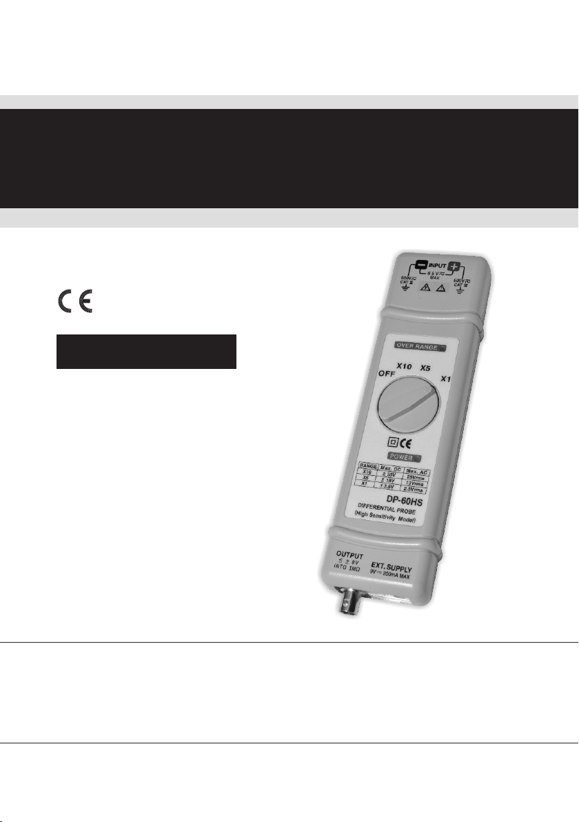
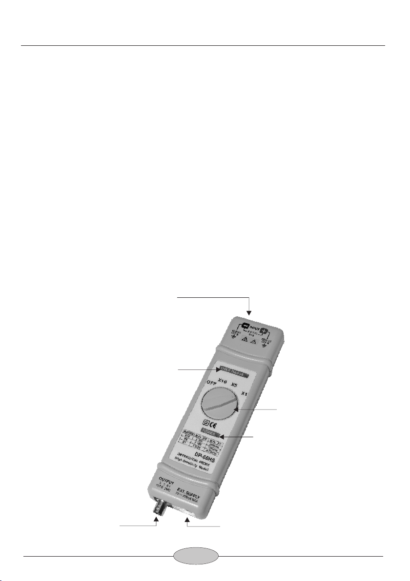
DP-60HS
差動測試棒
HIGH VOLTAGE DIFFERENTIAL PROBE
INSTRUCTION MANUAL
使用說明書
High Sensitivity Model


1. FEATURES
2. SPECIFICATIONS
3. PANEL DESCRIPTION
4. OPERATING ENVIRONMENTAL CONDITIONS
5. OPERATING PROCEDURE
6. EXT. POWER SOURCE
7. MAINTENANCE
8. CLEANING
9. WARRANTY
10. REPAIR
1
TABLE OF CONTENTS / 目次
1. 簡述
2. 規 格
3. 測試棒面板說明
4. 操作環境及狀況
5. 操作程序
6. 外接電源
7. 維護
8. 清潔
9. 保固
10. 維修
1
2
3
3
4
5
5
5
5
8
8
9
10
10
11
12
12
12
12
13
14
VOLTAGE DERATING CURVE / 耐壓曲線圖
ACCESSORIES / 附件圖

! Differential Voltage Probe,
Read the instructions before using the instrument:
1.Must acquire a differential voltage probe & get the best service
from instrument.
2.Read carefully the USER MANUAL.
3.Respect the safety precautions.
! SAFETY PRECAUTIONS
Warning, Risk of Electric Shock,
Respect the max input voltages
1.Max differential voltage: 70V (DC + AC peak) or 25V RMS
2.Max voltage between each input terminal and ground:600 V RMS
Do not use the probe in damp environment or where there is
risk of explosion.
Do not use the probe with its case open.
Disconnect the inputs and outputs of the probe before
opening the case.
! TO ORDER Differential Voltage Probe and Accessories:
An Insulated BNC/BNC lead and two ψ4 mm, length 3 inches(BP-
250).
Supplied a Adapter preset 9 V DC[115 V(SP-115) or 230 V(SP-
230)]
2 x high voltage IC clips(BP-256N.)
2 x Banana to Banana high voltage plug(BP-356N).
2 x Alligator plug(BP-276N).
Instruction Manual.

DP-60HS HIGH VOLTAGE DIFFERENTIAL PROBE
1. FEATURES
The DP-60HS differential voltage probe provides a safety means
of measuring floating potentials for all models of oscilloscopes
incomplete safety.
It converts the high differential voltage (≦ 70V peak) into a low
voltage (≦ 4.0V) with reference to the earth for display on the
oscilloscopes. It is designed specially for high sensitivity using.
The BNC output is designed to operate on an input with an
impedance of 1 MΩ. It is 2 times of the 50 Ω.
DP-60HS can observe more exact measured testing voltage from
DMM. (Oscilloscope accuracy is 3%, and DMM is 10 times).
2. SPECIFICATIONS
(1) Bandwidth:
DC - to 60 MHz (-3 dB) for x 10
DC - to 50 MHz (for x 5)
DC-to 15MHz(x1)
(2) Attenuation: x 10, x 5, or x 1
(3) Accuracy: +/- 2%
(4) Voltage Input Ranges (DC + AC peak to peak)
≦ 35 V for x 10, (i.e about 25 V RMS or 70 Vp-p)
≦ 18 V for x 5, (i.e about 13 V RMS or 36 Vp-p)
≦ 3.5 V for x 1, (i.e about 2.5 V RMS or 7 Vp-p)
(5) Permitted Max Input Voltage
Max differential voltage: 35 V (DC + AC peak to peak)
Max voltage between each input terminal and ground:
600 V RMS
1

2
DP-60HS Instruction Manual
(6) Input Impedance:
Differential: 1 MΩ // 2.5 pF
Between terminals and ground: 0.5 MΩ // 5 pF
(7) Output: ≦ +/- 4.0 V
(8) Output Impedance: 50 Ω
(9) Rise Time: 5.8 ns for x 10, 7.0 ns for x 5; 23 ns for x 1
(10) Rejection Rate on Common Mode:
60 Hz: > 80 dB ; 100 Hz: > 60 dB ; 1 MHz: > 50 dB
(11) Power Supply:
External 9 V DC power supply.
(12) Consumption: 120 mA max (1.1 WATT)
3. PANEL DESCRIPTION
Over Range Indicator
Input Connector
Output Connector External Power Source
Attenuation Function Switch
Power Indication

3
5. OPERATING PROCEDURE
!Connect to leads to the input and place the wire-grip on the
circuit to be tested.
!Connect the probe to the oscilloscope with the insulated
BNC/BNC lead.
!Adjust the vertical zero adjustment of the oscilloscope if
necessary.
!Select the attenuation ratio* and the vertical deviation of the
oscilloscope in accordance with the conversion table below.
!NB: The POWER light must come on.
The conversion table gives the real vertical deviation.
MAX Voltage Input
Range(DC+AC Peak)
X 10 X 5 X 1
± 35 V ± 18 V ± 3.5 V
4. OPERATING ENVIRONMENTAL CONDITIONS
(1) Dimensions and Weight:
195 x 55 x 30 mm; 250g
(2) Electrical Safety to IEC 1010-1
!Dual Insulation
!Installation Category III
!Degree of Pollution 2
!Rated Voltage or Max Live-Earth: 600 V RMS
(3) CE Mark
Conforms to EN 50081-1 and 50082-1 standards
Temperature
Relative Humidity
Reference Use Storage
+20°C … +30°C
70 % RH
0°C … +50°C
10 % … 85 % RH
-30°C … +70°C
10 % … 90 % RH
Attenuation
DP-60HS Instruction Manual

4
[N.B]
The real vertical deviation in V/div is equal to the attenuation
factor multiplied by the range of vertical deviation selected on
the oscilloscope. It will be doubled in the case of use of a 50 Ω
load.
Example:
With the probe on factor x 10, the oscilloscope on 0.5 V/div, the
real vertical deviation is 10 x 0.5 = 5 V/div.
With a 50Ω load on the input of the oscilloscope the deviation
becomes 2.5 V/div.
X 10 Range
Real Deviation In V/div
1
X 5 Range X 1 Range
50.5 2.5 0.5
20.2 1 0.2
10.1 0.5 0.1
0.550 m 0.25 50 m
0.220 m 0.1 20 m
0.110 m 50 m 10 m
50 m5 m 25 m 5 m
20 m2 m 10 m 2 m
6. EXT. POWER SOURCE
! Power consumption of the probe are 120 mA, thus it not suit for
battery, please use the accessory adapter only.
! If there are any damage on the adaptor, please contact us and
use the adaptor supply by us only. If the input power over 12V DC
will caused to the probe hard damage.
Vertical Deviation on the
Oscilloscope in V/div
10 5 1
DP-60HS Instruction Manual

7. MAINTENANCE
For maintenance, only use specified spare parts.
The manufacturer can not be held responsible for any accident
arising following a repair made other than its after sales service or
approved repairers.
8. CLEANING
This probe does not require any particular cleaning. If necessary,
clean the case with a cloth slightly moistened with soapy water.
9. WARRANTY
Unless notified to the contrary, our instruments are guaranteed
against any manufacturing defect or material defect. They do not
bear the specification known as the safety specification. Our
guarantee, which may not under any circumstances exceed the
amount of the invoiced price, goes no further than the repair of our
faulty equipment, carriage paid to our workshops.
10. REPAIR
Maintenance, repairs under or out of guarantee. Please return to
product to your distributor.
5
DP-60HS Instruction Manual

差 ,
! 前 閱 讀 說
1. 請先獲得一支差動測試棒
2. 從使用說明取得最佳維修及服務
3. 請詳讀使用者操作手冊
4. 請注意安全注意事項
! 安 注 意 項:
請小心注意觸電!
請注意最高輸入電壓!
最高差動電 壓: 70 V (DC + AC peak) 或 25 V RMS
輸入端及接地端間的最大差動電壓: 600V RMS
此 產 品在的 下有 爆 的風險下 作!
此 產 品此產品 的 盒蓋被打開!
打開此 產 品 的盒蓋 將 出入 斷!
! 訂 差 內 含
雙端BNC接 頭的測試纜線,長度3英呎(BP-250)
一個9 V DC 轉換器 [客戶必需指定115 V(SP-115)或230 V(SP-
230)]
一對高電壓專用的IC夾(BP-256N)
一對指定規格的雙端香蕉插頭高電壓 傳輸線(BP-356N)
一對高電壓專用的鱷魚夾(BP-276N)
使用說明書

DP-60HS 差動測試棒
1. 簡述:
DP-60HS差動測 試棒提供一個 安全的絕緣儀器給所有的示波
器使用, 它可 以轉換由高輸 入的差動電壓(≦70V PEAK) 進入
一個低電 壓(≦4.0V), 並且顯示波形在示波器上, 使用頻率高達
60 MHz, 是高靈敏度專用 型。
差動測試 棒輸出標示是設計在操作示波器1MΩ的輸入阻抗的
相對衰減 量, 當使用50 Ω匹配器時衰減 量剛好為2倍量。
DP-60HS差動測試棒, 也建議在數字電表上觀測更精確的實際
測試電壓值(示波器精確度為3%, 數字電表約精準10倍)。
2. 規:
(1) 頻寬:
DC - 60 MHz (-3dB) for x 10檔
DC - 50 MHz (衰減 x 5檔)
DC-15MHz ( x 1檔)
(2) 衰減: 共3檔 ( x 10, x 5, x 1)
(3) 精確度: +/- 2%
(4) 輸入電壓範圍 (DC + AC PEAK TO PEAK)
≦ 35 V for x 10, (約 25 V RMS 或 70 Vp-p)
≦ 18 V for x 5, (約 13 V RMS 或 36 Vp-p)
≦ 3.5 V for x 1, (約 2.5 V RMS 或 7 Vp-p)
(5) 允許最高輸入電壓:
最高差動 電壓: 35 V (DC + AC PEAK TO PEAK)
輸入端及 接地端間最高電壓: 600 V RMS
(6) 輸入阻抗:
差動: 1 MΩ//2.5 pF
單端到接 地端間的輸入阻抗: 0.5 MΩ// 5 pF
(7) 輸出電壓: ≦ +/- 4 V
8

3. 面板 說
DP-60HS 中 文 說 明 書
(8) 輸出阻抗: 50 Ω
(9) 上升時間:
5.8 ns for x 10 , 7 ns for x 5, 23 ns for x 1
(10) 雜 訊抑制率:
60 Hz: > 80 dB ; 100 Hz: > 60 dB ; 1 MHz: > 50 dB
(11) 電源:
指定外接9 V DC 電源(必須使用 本公司指定品)
(12) 耗 電: 最大耗電量120 mA (1.1 瓦特)
9
輸入端
過載指式燈
衰減量選擇及電源開關旋鈕
電源指示燈
外部電源引入端
輸出端

5. 作程
!將附件BP-356N 與 BP-256N (或BP-276N) 接起來後插入DP-
60HS 的 輸入端, 並將BP-256N (或BP-276N) 與測量 物接觸。
!將BP-250與DP-60HS的輸出端連接, 並與示波器連結。
!如有需要 先調整示波器上的垂直開關。
!將示波器 上的衰減率及垂直開關調整到一致的位置, 如下
表。
!注意: 電源必須打開。
最大輸入電壓
(DC+AC Peak)
X 10 X 5 X 1
± 35 V ± 18 V ± 3.5 V
4. 作 狀 況
(1) 尺寸及重量: 195 x 55 x 30 mm; 250g
(2) 電子安全規範 IEC 1010-1
!雙絕緣
!安裝類目 III
!污染程度 2
!相關電壓或最大接地: 600 V RMS
!CE: EN50081-1 及 50082-1
溫度
溼度
一般狀態 使用操作中 儲存
+20°C … +30°C
70 % RH
0°C … +50°C
10 % … 85 % RH
-30°C … +70°C
10 % … 90 % RH
衰減
10
DP-60HS 中 文 說 明 書

[注意]
實際的垂直偏向是等於衰減乘上示波器上所選擇的垂直偏向. 如果另
使用50Ω負載子時,際電值好是2倍量。
例如:
測試棒是 x 10, 示波器的垂 直偏向在 0.5, 其 實際的垂直偏向為:
10 x 0.5 = 5 V/div
示波器輸入的負載是50Ω, 偏 向就為2.5 V/div
示波器上的
垂直偏向(V/DIV)
換算實際偏向(V/DIV)
1
0.5
0.2
0.1
50 m
20 m
10 m
5 m
2 m
6. 外接電源
! 本產品因耗電量高達120mA, 因此指定使用電轉接器115V專用
(SP-115)或230V專用(SP-230)。
! 請勿使用非本公司指定品, 若因此造成任 何損毀, 本公司概不負
責。
11
X 10檔X 5檔X 1檔
5 2.5 0.5
2 1 0.2
1 0.5 0.1
0.5 0.25 50 m
0.2 0.1 20 m
0.1 50 m 10 m
50 m 25 m 5 m
20 m 10 m 2 m
10 5 1
DP-60HS 中 文 說 明 書

7. 護:
保養此產品時請使用原廠指定的工具. 原 廠將不負任何責任 由其他
不被認可的維修人員所做的維修。
8. 清:
此產品不需要任何特定的清潔. 如有需要, 請用輕軟乾淨的布沾上微
量的清潔液輕輕的在產品外觀擦拭。
9. 保固:
除了在人為上的特意損壞, 本產品是受保 固並可以維修的, 並不 包
含在安全規範的責任。
保固是以不超出發票上的金額, 零件的更 換及運送的費用。
保固是僅在正常操作下而造成的損壞. 並 不包含任何刻意的 損壞,
操作上的錯誤, 機械上的操作不當, 保養不當, 負 載或過壓。
原廠的保固僅包含有限的單純更換損 壞的零件. 使用者將不 可歸據
直接或間接的責任在原廠。
原廠的保固是賣出後的12個月內. 如有任意 的非原廠的維修或 更換
零件, 原廠保固將自然取消。
10. :
有任何的維修, 保養或更換零件是在保固以外, 請將產品退回 原廠
維修。
12
DP-60HS 中 文 說 明 書

Frequency
Voltage(DC+ACp-p)
10V
1KHz 10KHz 100KHz 1MHz 10MHz 100MHz
100V
1KV
10KV
(70V)
( 70V:1KHz / 50V:1MHz / 40V:60MHz / 30V:100MHz )
/ 耐 壓 曲 線Voltage Derating Curve
13
DP-60HS

Accessories / 附件圖:
BP-256N BP-250
BP-356N
BP-276N
(Adapter)
115V: SP-115
230V: SP-230
14


TINSE17 Ver.02
Table of contents
Other Pintek Measuring Instrument manuals

Pintek
Pintek PA-677 User manual

Pintek
Pintek PA-699 User manual

Pintek
Pintek DP-16K Series User manual

Pintek
Pintek DP-15K User manual

Pintek
Pintek DP-5205A User manual

Pintek
Pintek hvp-40 User manual

Pintek
Pintek PA-659 User manual

Pintek
Pintek HVP-10R User manual

Pintek
Pintek DP-25 User manual

Pintek
Pintek DP-16VF User manual