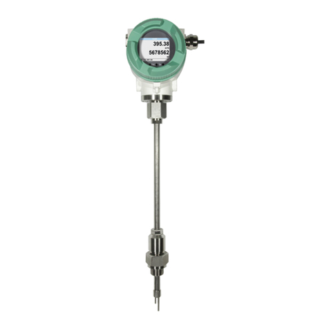
CS Instruments VA 452 Operator's manual

0970 0043 Ex Documentation VA 450/452 English, V1.4, 05.11.12 0970 0043 Ex Documentation VA 450/452 English, V1.4, 05.11.12
EX Documentation VA 450/452
上海萨海测量技术有限公司
电话:021-6236 2960
传真:021-5235 2321
网址:www.seasy-ist.com
VA 450 / VA 452
thermal mass flow sensor
EX- Documentation
11A Floor, D3 Building, TCL International E City, No. 1001
Zhongshanyuan Road, Nanshan District,
Shenzhen 518057, China
Tel: +86 (0)755 - 8619 3164
Fax: +86 (0)755 - 8619 3165
Email: sales@csinstrument.com
Website: http://www.csinstrument.com
CS Instruments (Shenzhen) Co. Ltd.
Room 1506, Hong Qiao Silver City Building, No.933
Zhongshan Road(w), Shanghai, China. 200051
Tel: +86 (0) 21-5111 3860
Fax: +86 (0) 21-5111 3861
Email: sales@csinstrument.com
Website: www.csinstrument.com
CS Instruments (Shanghai) branch
Asia Head Quarters
Room 31, Tower B, Cambridge Plaza,188 San Wan Road,
Sheung Shui, N.T. , Hong Kong
Tel: +86 (0)755 - 8619 3164
Fax: +86 (0)755 - 8619 3165
Email: sales@csinstrument.com
Website: www.csinstrument.com
CS Instruments (Asia) Co. Ltd.
Shanghai office
Hongkong office
This document contains important information for the installation
and operation of the flow sensor in explosive environments.
Please read the instructions carefully and follow the instructions
mentioned in this manual.
In case of any different specifications between this Ex Docu-
mentation and the Instruction Manual, the specification in the
Ex documentation is valid!

0970 0043 Ex Documentation VA 450/452 English, V1.4, 05.11.12 0970 0043 Ex Documentation VA 450/452 English, V1.4, 05.11.12
EX Documentation VA 450/452 EX Documentation VA 450/452
2 7
The installation and the supply connection must be done in compli-
ance with national regulations for devices used in potentially explo-
sive atmospheres.
The compliance with all of the technical data of the device is manda-
tory (see also nameplate).
Only qualified specialists who are trained in Ex-related issues are
allowed to install, connect the electricity and maintain the device
The device should be opened in a non-explosive atmosphere or in a
de-energized state where a delay of 5 minutes after power down has
to be ensured.
No connection of service-kit or any other devices are permitted if the
atmosphere is considered to be explosive.
When opening the enclosure make sure that no dust or moisture
enters into the casing.
Ensure that cable entries are tightly sealed
Materials which come in contact with the medium are of stainless
steel 1.4404 / 316L and of sealing rubber NBR.
Important
information
Special
Attention
The device must be connected to the potential equalization system.
Please refer to page 5 regarding "Potential equalization"
1. Warnings

0970 0043 Ex Documentation VA 450/452 English, V1.4, 05.11.12 0970 0043 Ex Documentation VA 450/452 English, V1.4, 05.11.12
EX Documentation VA 450/452 EX Documentation VA 450/452
36
To all terminals of the flow transmitter, only devices with ratings Um
≤24 V DC and Im ≤500 mA are allowed to be connected.
The flow transmitter is only allowed to be used in the permitted tem-
perature class.
For ambient temperatures below –20 °C cables, drain plugs, cable
glands and cable entries must be suitable and certified.
Cables and pipe entries must be certified (Ex d IIC) and must be
suitable for operating temperatures of up to 105 °C. When using pipe
entries, the associated sealing equipment must be fitted directly at
the housing.
The cable entries and openings not used must be sealed tight with
suitable components.
The rotation of the display is only allowed during installation and in
non explosive environment! Before rotating the local display make
sure that the device is powered off for at least 5 minutes.
The display version of VA 452 can be rotated in both directions
270°. For this purpose the nut at the top of the s haft has to be
opened fully. Then pull up the metal casing and rotate it in the de-
sired direction. It can be rotated in 90°steps in both directions. A
metal pin locks the position. When the desired position is achieved,
press down the metal casing onto the shaft so that the metal pin can
insert into the position hole. Tighten up the nut.
Important
notes
2. Installation
Examination
certificate,
certificates of
conformity
The system meets the fundamental health and safety requirements
for the design and construction of devices and protective systems
intended for use in potentially explosive atmospheres in accordance
with appendix II of directive 94/9/EC.
Other tech-
nical infor-
mation
Since this manual only contains ex-relevant information please refer
to the instruction manual of VA 450 and VA 452 for technical data
and further information.
Front and
back cover
security seal
The front and back cover of the instrument are secured with a screw
to avoid the opening of the covers through unauthorized persons.
Please ensure that both security screws are tighten up after finishing
the installation!
Security screws at back and front cover
Used
standards
EN 60079-0:2009
EN 60079-1:2007

0970 0043 Ex Documentation VA 450/452 English, V1.4, 05.11.12 0970 0043 Ex Documentation VA 450/452 English, V1.4, 05.11.12
EX Documentation VA 450/452 EX Documentation VA 450/452
4 5
Name plate
Potential
equalization
For the safety of the operation in explosive environment the potential
equalization is very important. The device has a screw terminal out-
side the enclosure to connect the earth signal.
The device can also be integrated to the equalization through the
pipeline as long the earth connection is conform to regulations.
Temperature
range
Cable entries
The cable glands/entries must be secured to prevent working loose
and the seals have to be installed immediately adjacent to the cas-
ing.
Please ensure that the cable entries and cable glands are leak-tight!
The cable s used must be manufactured in a way that the build-up
of electrostatic charges are avoided!
Only following cable glands, reducers and closers are allowed to be
used and can be ordered at CS Instruments:
Cable outer diameter must be between 7.0 … 12 mm!
Service kit
No connection of service-kit or any other devices are permitted if the
atmosphere is considered to be explosive.
Alternatively device settings can be done through the integrated
Bluetooth interface with a portable notebook if the notebook is ap-
proved for usage in explosive environment. Please contact our ser-
vice for available devices and software.
Fuse
The power supply for the flow transmitter needs to have a fuse with
following specification:
Voltage 16 to 30 DC, fuse 0.5 A slow blow (according to IEC 127)
ATTENTION: The minimum temperature for fluid and ambient is –30
ºC
1) Sensor type
2) Item number
E.g.: 25110001
25 – week of the year
11 – year
0001 – counting number
3) Serial number
4) Power supply and power consumption
5) Medium pressure range
6) Medium temperature range
7) Ambient temperature range
8) Caution information
9) ATEX symbol
10) CE marking
11) Indication of type of protection, explosion group,
temperature class, ingress protection
12) Company name and address
Hummel Cable
Order No. Description Thread size entry
Gland 1.622.2000.51 HSK-M-Ex-d / Metr M20 x 1.5 7 - 12 mm
Gland 1.622.1600.51 HSK-M-Ex-d / Metr M16 x 1.5 3 - 7 mm
Reducer 1.879.2016.50 RSD-MS-Ex-d / Metr. M20 x 1.5 >
M16 x 1.5
Blind plug1.877.2000.50 V-Ms-Ex-d / Metr. M20 x 1.5

0970 0043 Ex Documentation VA 450/452 English, V1.4, 05.11.12 0970 0043 Ex Documentation VA 450/452 English, V1.4, 05.11.12
EX Documentation VA 450/452 EX Documentation VA 450/452
36
To all terminals of the flow transmitter, only devices with ratings Um
≤24 V DC and Im ≤500 mA are allowed to be connected.
The flow transmitter is only allowed to be used in the permitted tem-
perature class.
For ambient temperatures below –20 °C cables, drain plugs, cable
glands and cable entries must be suitable and certified.
Cables and pipe entries must be certified (Ex d IIC) and must be
suitable for operating temperatures of up to 105 °C. When using pipe
entries, the associated sealing equipment must be fitted directly at
the housing.
The cable entries and openings not used must be sealed tight with
suitable components.
The rotation of the display is only allowed during installation and in
non explosive environment! Before rotating the local display make
sure that the device is powered off for at least 5 minutes.
The display version of VA 452 can be rotated in both directions
270°. For this purpose the nut at the top of the s haft has to be
opened fully. Then pull up the metal casing and rotate it in the de-
sired direction. It can be rotated in 90°steps in both directions. A
metal pin locks the position. When the desired position is achieved,
press down the metal casing onto the shaft so that the metal pin can
insert into the position hole. Tighten up the nut.
Important
notes
2. Installation
Examination
certificate,
certificates of
conformity
The system meets the fundamental health and safety requirements
for the design and construction of devices and protective systems
intended for use in potentially explosive atmospheres in accordance
with appendix II of directive 94/9/EC.
Other tech-
nical infor-
mation
Since this manual only contains ex-relevant information please refer
to the instruction manual of VA 450 and VA 452 for technical data
and further information.
Front and
back cover
security seal
The front and back cover of the instrument are secured with a screw
to avoid the opening of the covers through unauthorized persons.
Please ensure that both security screws are tighten up after finishing
the installation!
Security screws at back and front cover
Used
standards
EN 60079-0:2009
EN 60079-1:2007
上海萨海测量技术有限公司
电话:021-6236 2960
传真:021-5235 2321
网址:www.seasy-ist.com
Other manuals for VA 452
1
This manual suits for next models
1
Table of contents
Other CS Instruments Measuring Instrument manuals

CS Instruments
CS Instruments DS 500 User manual

CS Instruments
CS Instruments DP 400 mobil User manual

CS Instruments
CS Instruments FA 410 User manual

CS Instruments
CS Instruments DP 500 Instruction manual

CS Instruments
CS Instruments DS 350-P Installation manual

CS Instruments
CS Instruments LD 500 User manual

CS Instruments
CS Instruments 0554 0504 User manual

CS Instruments
CS Instruments VA 520 User manual

CS Instruments
CS Instruments FA 300-2 Ex User manual

CS Instruments
CS Instruments VA 550 Ex User manual