CT-S830S,
CT-S830S-G
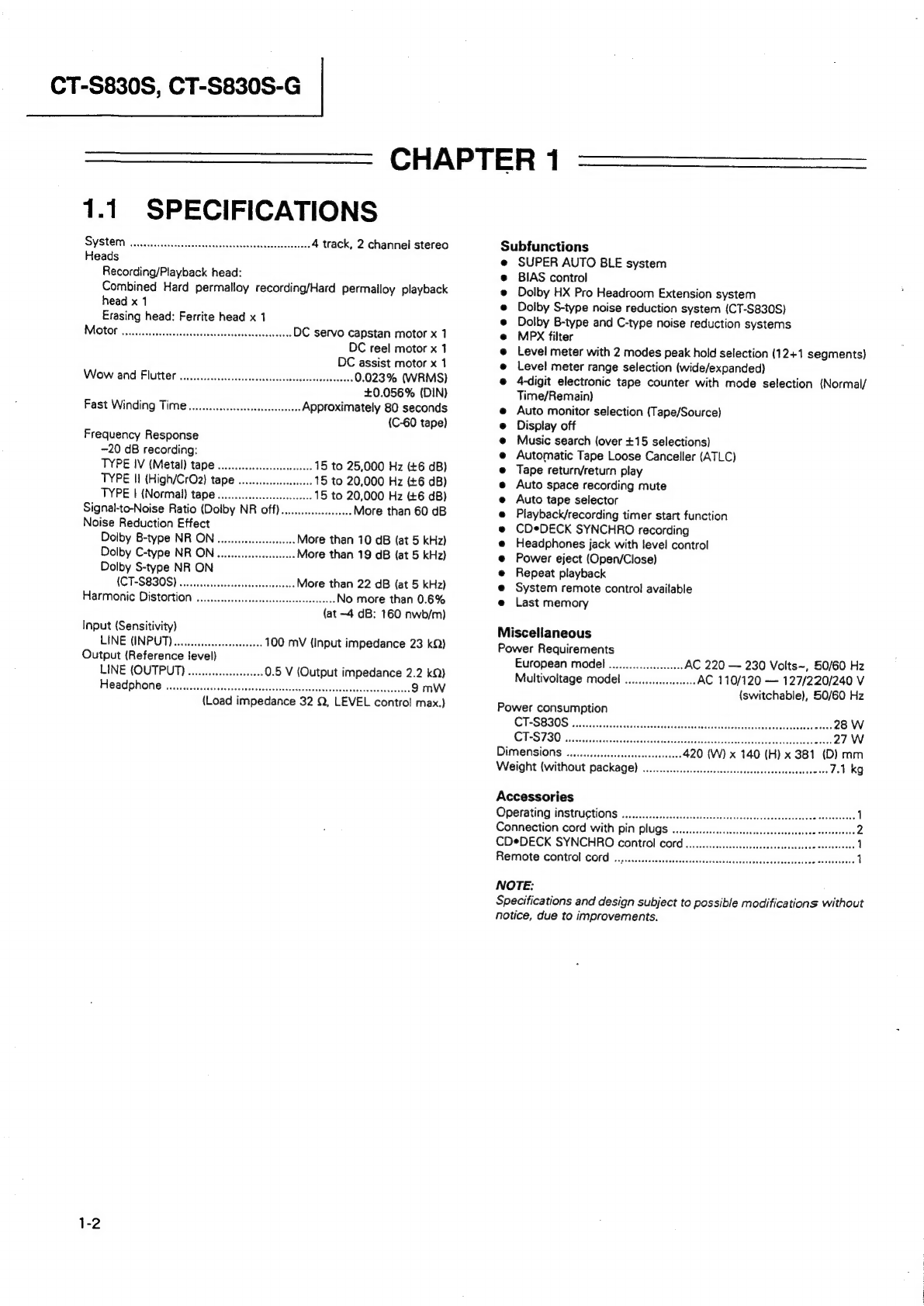
1.1.
SPECIFICATIONS
S31
a
ea
4
track,
2
channel
stereo
Recording/Playback
head:
Combined
Hard
permalloy
recording/Hard
permalloy
playback
head
x
1
Erasing
head:
Ferrite
head
x
1
MO
t8
oss
tosecs
csacensaveseostewseeetisdscchevees
DC
servo
capstan
motor
x
1
DC
reel
motor
x
1
DC
assist
motor
x
1
Wow
and
Flutter
....
ccc
cecccsscssescecscsecececessessscnens
0.023%
(WRMS)
+0.056%
(DIN)
Fast
Winding
Time
.......cccceeececsscececseees
Approximately
80
seconds
(C-60
tape)
Frequency
Response
-20
dB
recording:
TYPE
IV
(Metal)
tape
wo...
15
to
25,000
Hz
(+6
dB)
TYPE
II
(High/CrO2)
tape
.
-.
15
to
20,000
Hz
(+6
dB)
TYPE
|
(Normal)
tape
.......
.-
15
to
20,000
Hz
(£6
dB)
Signal-to-Noise
Ratio
(Dolby
NR
off)
.....c.ccscceeeeee
More
than
60
dB
Noise
Reduction
Effect
Dolby
B-type
NR
ON
Dolby
C-type
NR
ON
Dolby
S-type
NR
ON
(CT-S8308)
.....ccccccescccsssscescesecesees
More
than
22
dB
(at
5
kHz)
Harmonic
Distortion
......ccecsesescssecescereesetesceees
No
more
than
0.6%
(at
~4
dB:
160
nwb/m)
More
than
10
dB
(at
5
kHz)
More
than
19
dB
{at
5
kHz)
Input
(Sensitivity)
LINE
(INPUT)...
eee
eeseseeees
100
mV
(Input
impedance
23
kQ)
Output
(Reference
level)
LINE
(OUTPUT)
..........ceeccscaes
0.5
V
(Output
impedance
2.2
kQ)
FASO
PHONE
scensetcsssvvscerescuceses
docu
dscensbeotesduaveshanvneewasecaieesecs
9
mW
(Load
impedance
32
Q,
LEVEL
contro!
max.)
CHAPTER
1
Subfunctions
SUPER
AUTO
BLE
system
BIAS
control
Dolby
HX
Pro
Headroom
Extension
system
Doiby
S-type
noise
reduction
system
(CT-S830S)
Dolby
B-type
and
C-type
noise
reduction
systems
MPX
filter
Level
meter
with
2
modes
peak
hold
selection
(12+1
segments}
Level
meter
range
selection
(wide/expanded)
4-digit
electronic
tape
counter
with
mode
selection
(Normal/
Time/Remain)
Auto
monitor
selection
(Tape/Source)
Display
off
Music
search
(over
+15
selections)
Automatic
Tape
Loose
Canceller
(ATLC)
Tape
return/return
play
Auto
space
recording
mute
Auto
tape
selector
Playback/recording
timer
start
function
CDeDECK
SYNCHRO
recording
Headphones
jack
with
level
control
Power
eject
(Open/Close)
Repeat
playback
System
remote
control
available
Last
memory
Miscellaneous
Power
Requirements
European
model
............0ccc00
AC
220
—
230
Volts~,
50/60
Hz
Multivoitage
model
...
seve
AC
110/120
—
127/220/240
V
(switchable),
50/60
Hz
Power
consumption
CT+S8B0S
..csssessnstevsevsadessseissasvescsieceesserneal
eeadestciulgaanaee
ade
28
W
CTS
TSO
isseciascassatdeevceccssttatesatevsvtatasicassruand
easivs
Aeioeieamrscent
27W
Dimensions
........cccccseeeee
420
(W)
x
140
(H)
x
381
(D)
mm
Weight
(without
package)
.......cccccceseecccssesesscessecssecsessessee
ees
7.1
kg
Accessories
Operating
instructions
.......cccecesssssssssscesscssesececsesssesestcsesssece
cesverecees
Connection
cord
with
pin
plugs
.............
CDeDECK
SYNCHRO
control
cord.........
SAY
Remote
Control
COP
..,....ccccssessssssssssssrcacstscsesssacsecsecacsescecee
eeseatavaee
NOTE:
Specifications
and
design
subject
to
possible
modifications
without
notice,
due
to
improvements.


