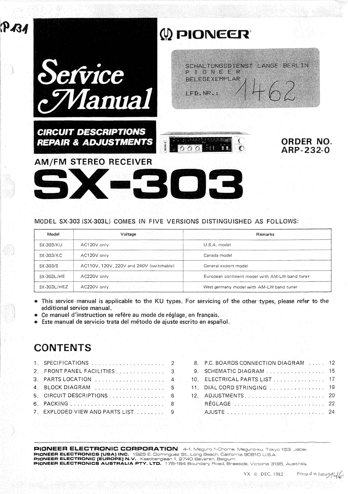
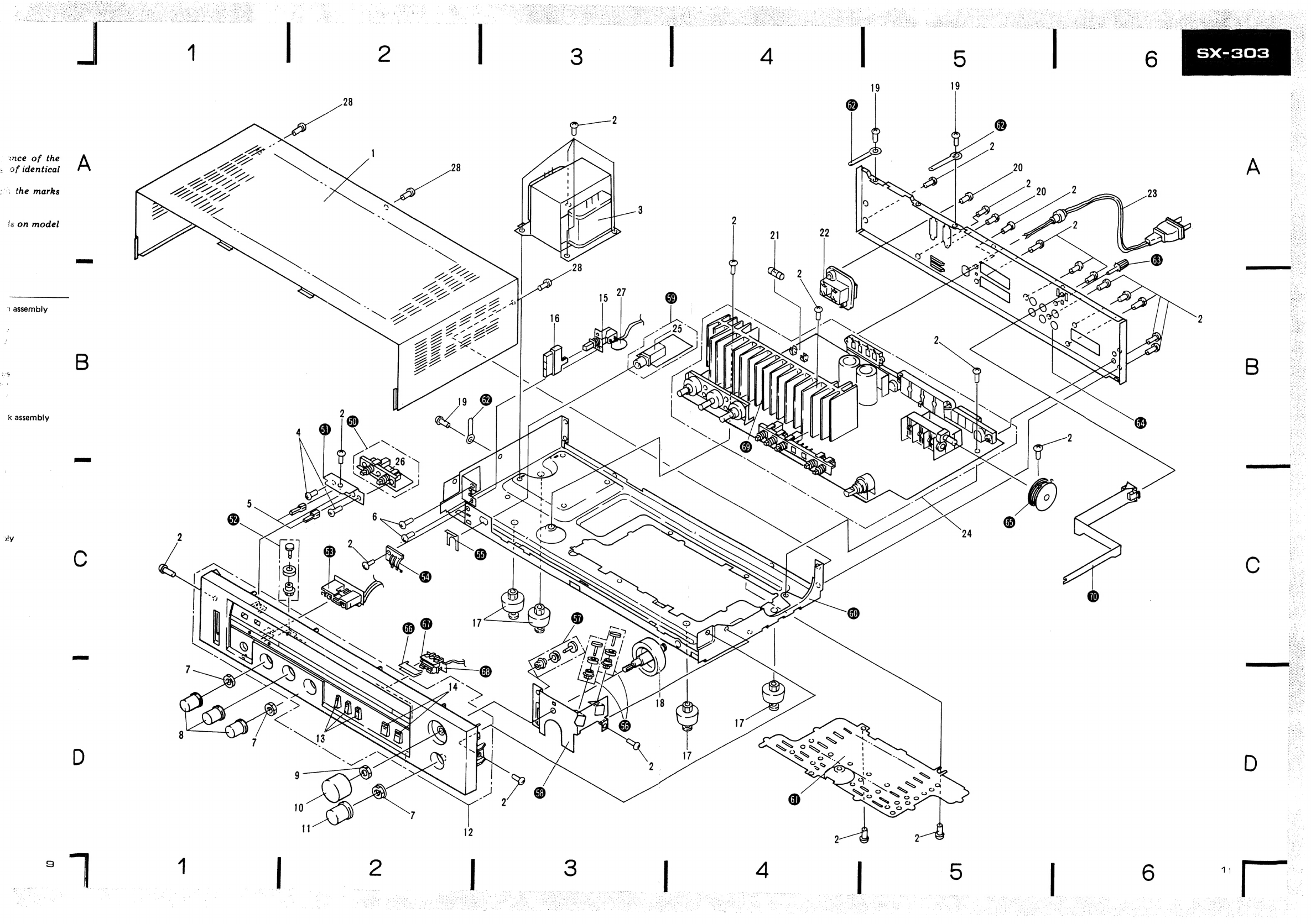
Pioneer SX-303 User manual
Other Pioneer Receiver manuals

Pioneer
Pioneer MVH-S522BS User manual

Pioneer
Pioneer X-HM31V-K User manual

Pioneer
Pioneer MVH-S320BT User manual

Pioneer
Pioneer VSX-609RDS User manual

Pioneer
Pioneer XV-HA5 User manual

Pioneer
Pioneer VSX-504S User manual

Pioneer
Pioneer X-HM81-K User manual

Pioneer
Pioneer VSX-1019AH-K User manual

Pioneer
Pioneer VSX-72TXV-S User manual

Pioneer
Pioneer XV-HTD1 User manual

Pioneer
Pioneer SC-LX502 Installation guide

Pioneer
Pioneer VSX-918V-K User manual

Pioneer
Pioneer VSX-818V User manual

Pioneer
Pioneer SC-75 User manual

Pioneer
Pioneer VSX-D710S User manual

Pioneer
Pioneer Elite VSX-90TXV User manual

Pioneer
Pioneer VSX-819H-S User manual

Pioneer
Pioneer MVH-S620BT User manual

Pioneer
Pioneer MVH-330DAB User manual

Pioneer
Pioneer VSX-1012-K User manual