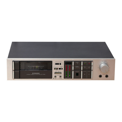
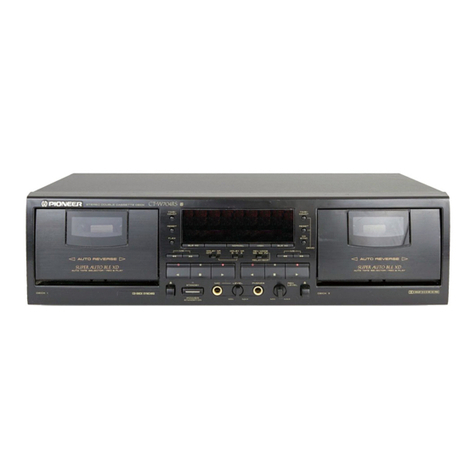
Pioneer CT-70R User manual

VY)
PIONEER’
Setvice
PAZETTET
REPAIR
&
ADJUSTMENTS
ORDER
NO.
ARP-
260-0
STEREO
CASSETTE
TAPE
DECK
Cir-
7OR
MODEL
CT-70R
COMES
IN
SEVEN
VERSIONS
DISTINGUISHED
AS
FOLLOWS:
~T
Whom;
.
|
Type
Voltage
Remarks
KU
AC120V
only
U.S.A.
model
__|
KC
AC120V
only
Canada
model
+
HE
AC220V,
240V
(switchable)
European
continent
model
HB
AC220V,
240V
(switchable)
United
Kingdom
model
AC220V,
240V
(switchable)
Australia
model
AC120V,
220V,
240V
(switchable)
General
export
model
AC120V,
220V,
240V
(switchable)
U.S.
Military
model
This
service
manual
is
applicable
to
the
KU
type.
For
servicing
of
the
other
types,
please
refer
to
pp.
66~76.
For
the
circuit
and
mechanism
descriptions,
please
refer
to
the
CT-90R
service
manual
(ARP-364-0).
Ce
manuel
d’instruction
se
refére
au
mode
de
reglage,
en
francais.
Este
manual
de
servicio
trata
del
método
de
ajuste
escrito
en
espajiol.
CONTENTS
1.
SPECIFICATIONS
......0.0.
050055
085
ea%
3
9.
ELECTRICAL
PARTS
LIST
..............
33
2.
FRONT
PANEL
FACILITIES
.............
4
10.
ADJUSTMENTS
..........
0.0.0.
cee
eee
38
3.
DISASSEMBLY
.............
00.0
00000-
8
REGU
AGE
soc
skeek
eae
ok
seek
Cav
awe
47
4.
PARTS
LOCATION
................004.
10
ASUSTEES
2.3
Gace
a
Periebdetesabs
achudee
o
alierccd
SBE
S
56
5S,
‘EXPLODED
VIEW:
s
2
pg
gees
gee
gine
ams
12
11.
SUPPLEMENT
FOR
HE,
HBANDHPTYPES
..
66
6:
PACKING
«5
esea
dead
cedaarevss
dee
ews
18
12.
SUPPLEMENT
FOR
KC
TYPE
............
71
7.
P.C.
BOARDS
CONNECTION
DIAGRAM
.....
20
13.
SUPPLEMENT
FOR
D
AND
D/G
TYPES
....
72
8.
SCHEMATIC
DIAGRAM
................
27
PIONEER
ELECTRONIC
CORPORATION
3-1,
Meguro
1-Chome,
Meguro-ku,
Tokyo
153,
Japan
PIONEER
ELECTRONICS
(USA)
INC.
1925
E.
Dominquez
St.,
Long
Beach,
California
90810
U.S.A.
PIONEER
ELECTRONIC
[EUROPE]
N.V.
Keetbergiaan
1,2740
Beveren,
Belgium
PIONEER
ELECTRONICS
AUSTRALIA
PTY.
LTD.
178-184
Boundary
Road,
Braeside,
Victoria
3195,
Australia
YH
©
MAY
1983
Printed
in
Japan
an

CT-70OR
SAFETY
INFORMATION
1.
SAFETY
PRECAUTIONS
The
following
check
should
be
performed
for
the
continued
protection
of
the
customer
and
service
tech-
nician.
LEAKAGE
CURRENT
CHECK
Measure
leakage
current
to
a
known
earth
ground
(water
pipe,
conduit,
etc.)
by
connecting
a
leakage
current
tester
such
as
Simpson
Model
229-2
or
equivalent
between
the
earth
ground
and
all
exposed
metal
parts
of
the
appli-
ance
(input/output
terminals,
screwheads,
metal
overlays,
control
shaft,
etc.).
Plug
the
AC
line
cord
of
the
appliance
directly
into
a
120V
AC
60Hz
outlet
and
turn
the
AC
power
switch
on.
Any
current
measured
must
not
exceed
0.5mA.
Leakage
current
tester
Reading
should
not
be
above
0.5mA
Test
all
exposed
metal
surfaces
2-wire
cord
@
Also
test
with
}
plug
reversed
1
Earth
(Using
AC
adapter
"ground
plug
as
required)
AC
Leakage
Test
ANY
MEASUREMENTS
NOT
WITHIN
THE
LIMITS
OUTLINED
ABOVE
ARE
INDICATIVE
OF
A
PO-
TENTIAL
SHOCK
HAZARD
AND
MUST
BE
COR-
RECTED
BEFORE
RETURNING
THE
APPLIANCE
TO
THE
CUSTOMER.
2.
PRODUCT
SAFETY
NOTICE
Many
electrical
and
mechanical
parts
in
the
appliance
have
special
safety
related
characteristics.
These
are
often
not
evident
from
visual
inspection
nor
the
protection
afforded
by
them
necessarily
can
be
obtained
by
using
replacement
components
rated
for
voltage,
wattage,
etc.
Replacement
parts
which
have
these
special
safety
charac-
teristics
are
identified
in
this
Service
Manual.
Electrical
components
having
such
features
are
identified
by
marking
with
a
A\
on
the
schematics
and
on
the
parts
list
in
this
Service
Manual.
The
use
of
a
substitute
replacement
component
which
dose
not
have
the
same
safety
characteristics
as
the
PIONEER
recommended
replacement
one,
shown
in
the
parts
list
in
this
Service
Manual,
may
create
shock,
fire,
or
other
hazards.
Product
Safety
is
continuously
under
review
and
new
instructions
are
issued
from
time
to
time.
For
the
latest
information,
always
consult
the
current
PIONEER
Service
Manual.
A
subscription
to,
or
additional
copies
of,
PIONEER
Service
Manual
may
be
obtained
at
a
nominal
charge
from
PIONEER.

1.
SPECIFICATIONS
SYSTEM:
iccidatie
netted
hateeedters
Compact
cassette,
2-channel
stereo
HeadSicccodscngeevceduedeaecnces
“Ribbon
Sendust”’
recording/
playback
head
x1
erasing
head
x
2
Mtor
iisisecsestendvltaven
bibeatasbestecondeesnnds
DC
servo
capstan
motor
x
1
DC
ree!
motor
x
2
Wow/
Flutter
.........:ccecceeeceeceeeeeeeens
No
more
than
0.03%
(WRMS)
No
more
than
+
0.16%
(DIN)
Fast
Winding
Time
................00.08
Approx.
90
seconds
(C-60
tape)
Frequency
Response
—
20
dB
recording:
Normal
ta00
visisccsiscecssscescsedseeverscssgatweesevaensve
25
to
17,000
Hz
(30
to
16,000
Hz
+
3
dB)
CHROME
tape
nice
see
ctictdinaionesevs
ideas
a
euenee
deeb
oe
25
to
17,000
Hz
(30
to
17,000
Hz
+
3
dB)
Metal
tape:
.ecccscccictiisevetedesciaceccssdeisiarsevecmacave
25
to
19,000
Hz
(30
to
18,000
Hz
+
3
dB)
0
dB
recording:
NOFMal
tape
sepsis
sowed
sonveeasdte
pes
eseneensbdsvees
ebend
tea
er
25
to
9,000
Hz
Chrome
tape
...........ccceccecccusesccceseeveneecaeeeueueees
25
to
9,000
Hz
Metal
tape
...........ccccceccsceescucececcveueeseeesaeueuees
25
to
14,000
Hz
Signal-to-Noise
Ratio
Dolby
NR
OFF
00.0...
cccecceceececsecceesecvesaeeeeueues
More
than
58
dB
Noise
Reduction
Effect
Dolby
type
B
NR
ON
.................:ee
eee
More
than
10
dB
(at
5
kHz)
Dolby
type
CNRON
........
eee
More
than
19
dB
(at
5
kHz)
Harmonic
Distortion
(Metal
tape)
No
more
than
1.0
%
(0
dB)
Input
(Sensitivity)
MIC
(L,R)
2...
ee
ee
ee
0.25
mV,
6
mm
diam.
jack
(Source
impedance
600
2}
LINE
(INPUT)
..
0...
..20....
0.200000
0008
70
mV
(Input
impedance
50
k&
or
more)
Output
(Reference
level)
LINEMOUT
PUR)
ice
ee
ree
iat
hee
EE
AG
vee
ds
450
mV
(Output
impedance
10
k&
or
less)
Headphones...
2...
es
0.3
mW
(Load
impedance
82)
SUBFUNCTIONS
©
Recording
playback
auto
reverse
(Quick
reverse)
¢
Dolby
NR
system
(type
B
and
C)
Music
search
function
Skip
function
Index
scan
Blank
search
Music
repeat
Auto
tape
selector
function
4-digit
tape
counter
12
Segment
level
meter
(LED)
Wired
remote
control
Timer
standby
function
REC
muting
function
MISCELLANEOUS
Power
Requirements
KU
KG
models
enced
teeta
cto
ssa
chag
een
ae
eke
AC
120
V,
60
Hz
HE,
H&
and
HP
models
.........
AC
220/240
V,
50/60
Hz
(switchable)
D,
D/G
models
...............
AC
120/220/240V,
50/60
Hz
(switchable)
Power
Consumption
KAD,
BG
IMOGEIS
se
eaha
ls
evel
ig
leadun
suas
veceks
cociwiaiwe
telat:
51
watts
HE,
HB
and
HP
models
...
5Owatts
De
D/G
Models)
ficccse
es
o0-
asc
ve
caeccna
eee
oas
alate
areeeuabe
ccna
40
watts
Dimensions...
s256.255
cesesnevieasahs
sanseeee
420
(W)
x
120
(H)
x
355
(D)
mm
16-9/
16
(W)
x
4-12/16
(H)
x
14(D)
in
Weight
(without
packaging)
............cccccseseeneeeee
ee
6.6
kg
(14
Ib
9
oz)
FURNISHED
PARTS
Operating
instructions
............cccecccceeseeeeea
seca
eeeeneeeenseneeneeanees
1
Connection
cord
assembly
............cceccceceecucecevencessaceeeeeneeerenees
2
NOTES:
1.
Reference
Tapes:
Normal
&
LH:
DIN
44513/BLATTE
or
equiv.
CrO,
DIN
45513/BLATT7
(CrO,)
or
equiv.
2.
Reference
Recording
Level:
Meter
0
dB
indicating
level
(160
nwb/m
magnetic
level
=
Philips
cassette
reference
level)
3.
Reference
Signal:
315
Hz
4.
Wow
&
Flutter:
©
JIS
(3
kHz,
with
acoustic
compensation
(weighted)
rms
value);
DIN
3,150Hz
with
acoustic
compensation
tion
(weighted)
PEAK
value
DIN
45507
5.
Frequency
Response:
*
Measured
at
—
20
dB
level,
DOLBY
NR
OFF,
level
deviation
is
+
€
dB
without
indication.
6.
Signal-to-Noise
Ratio:
¢
Measured
at
3rd
harmonic
distortion
3%
level,
weighted
(DIN
45513/BLATT7)
7.
Sensitivity:
Input
level
(mV)
required
for
reference
recording
tevel
with
input
(REC)
fevel
control
set
to
maximum
8.
Reference
Output
Level:
Playback
output
level
when
meter
in-
dicates
0
dB.
9.
This
model
does
not
employ
a
recording/playback
connector
(DIN-type).
NOTE:
Specifications
and
the
design
are
subject
to
possible
modifications
without
notice
due
to
improvements.
2.
FRONT
PANEL
FACILITIES
“@
AUTO
REVERSE
>
2
PRONMEER
ertmes
Camm
TTE
ane
DaCx
@
POWER
SWITCH
(POWER)
The
power
is
switched
on
when
this
switch
is
pressed.
Release
the
switch
to
turn
off
the
power.
e
After
the
switch
is
set
to
the
ON
position,
the
muting
circuit
is
activated
and
so
the
unit
will
not
operate
for
about
4
seconds.
e
When
the
POWER
switch
is
set
to
OFF
while
the
tape
deck
is
operating,
the
operational
mode
is
released
and
the
unit
is
set
to
the
stop
mode.
e
When
the
POWER
switch
is
set
to
ON
while
the
TIMER
switch
is
at
the
REC
or
PLAY
position,
the
recording
or
playback
mode
is
established
automatically.
Make
sure
that
the
TIMER
switch
is
at
OFF
when
an
unattended
recording
or
wake-up
playback
opera-
tion
is
not
to
be
performed.
e
When
the
POWER
switch
is
set
to
ON,
the
head
section
func-
tions
momentarily.
This
is
normal
and
not
an
indication
of
a
malfunction.
@
TIMER
START
SWITCH
(TIMER)
This
switch
is
used
when
an
optional
audio
timer
is
employed
for
unattended
recording
or
wake-up
playback
operations.
Keep
this
switch
at
the
OFF
position
when
the
timer
is
not
being
used.
REC:
Set
to
this
position
to
set
the
tape
deck
automatically
to
the
recording
mode
at
the
time
preset
on
the
audio
timer
and
to
start
the
recording
of
programs
unattend-
ed,
for
instance.
OFF:
For
when
the
timer
is
not
being
used.
PLAY:
Set
to
this
position
to
set
the
tape
deck
automatically
to
the
playback
mode
at
the
time
preset
on
the
audio
timer
and
to
start
the
playback.
The
tape
playback
function
can
be
used
to
wake-up
in
the
morning
instead
of
an
alarm
clock.
©
EJECT
BUTTON
(EJECT)
The
cassette
door
opens
when
this
button
is
pressed.
When
it
is
pressed
while
the
tape
is
traveling
or
during
a
recording
or
playback
standby
operation,
noise
will
be
generated
and
possible
malfunc-
tioning
may
occur.
Even
if
pressed,
the
cassette
door
will
not
open.
©
CASSETTE
DOOR
@
DIRECTION
SWITCH
(DIRECTION)
Press
this
switch
to
select
the
direction
in
which
the
tape
is
to
travel.
When
the
tape
is
moving
forward
and
the
switch
is
pressed,
the
tape
direction
is
reversed;
when
the
tape
is
moving
in
the
reverse
direction,
it
starts
moving
forward.
The
direction
indicator
lights
up
to
show
the
direction
of
the
tape
movement.
Since
the
tape’s
direc-
tion
can
be
reversed
with
a
push
of
this
switch,
there
is
no
need
to
turn
over
the
tape
and
re-load
it.
When
this
switch
is
pressed
even
in
the
playback
or
recording
standby
mode,
the
tape’s
direction
is
reversed.
@
DIRECTION
INDICATORS
These
indicate
the
direction
of
the
tape
transport.
@
TAPE
COUNTER
The
numbers
change
as
the
tape
is
playing.
Tape
position
is
in-
dicated
with
a
four-column
digital
counter.
@
RESET
BUTTON
(RESET)
Depressing
this
button
resets
the
tape
counter
to
“‘0000’’.
Depress
this
button
before
recording
or
playback
to
reset
the
counter
to
0000".
If
you
make
a
memo
of
the
tape
contents
and
correspon-
ding
tape
counter
numbers
during
recording
and
playback,
you
will
have
an
index
of
the
programs
on
the
tape
enabling
you
to
conve-
niently
find
any
desired
program
on
the
tape.

@
MEMORY
SWITCH
Memory
stop
operations
can
be
performed
when
this
switch
is
pressed
to
the
ON
position.
The
tape
counter
is
set
to
’’0000’’
beforehand
and
the
tape
is
rewound.
As
soon
as
the
tape
is
re-
wound
to
the
‘‘0000"'
position,
it
stops
automatically.
Use
this
func-
tion
to
rewind
a
recorded
program
and
play
it
back
immediately
or
to
repeatedly
listen
to
the
same
program.
Normally,
this
switch
is
kept
at
the
released
OFF
position.
The
memory
stop
function
also
operates
in
the
fast
forward
mode.
@
PLAY
SWITCH
(PLAY)
Depress
this
switch
to
playback
a
tape.
@
PLAY
INDICATOR
(m)
@
REW
SWITCH
(<x)
Depress
this
switch
to
rewind
the
tape
at
high
speed
(The
tape
will
travel
from
right
to
left).
@®
FF
SWITCH
(co)
Depress
this
switch
to
send
the
tape
forward
at
high
speed
(The
tape
will
travel
from
left
to
right).
@
STOP
SWITCH
(sTopP)
Depress
this
switch
to
stop
the
tape
travel
and
to
release
the
Operating
switches.
@
DOLBY
INDICATORS
(DOLBY
NR)
These
light
when
the
DOLBY
NR
switch
is
set
to
ON
(
=
).
[B}:
This
lights
when
the
B
type
Dolby
noise
reduction
system
is
operating.
IC]:
This
lights
when
the
C
type
Dolby
noise
reduction
system
is
operating.
@
PAUSE
SWITCH
(PAUSE)
Press
to
temporarily
stop
the
tape
transport
in
the
playback
or
recor-
ding
mode.
At
times
like
this,
the
pause
indicator
(#—)
lights.
When
pressed
again,
the
pause
function
is
released
and
the
tape
starts
to
travel
again.
The
switch
does
not
function
in
the
fast
forward
or
re-
wind
modes.
When
it
is
pressed
in
the
stop
mode,
the
pause
in-
dicator
lights;
when
it
is
pressed
again,
the
unit
is
reset
to
the
stop
mode
and
the
tape
does
not
move.
@
PAUSE
INDICATOR
(18)
This
lights
when
the
unit
is
set
to
the
pause
mode.
@
RECORDING
SWITCH
(REC)
This
switch
is
depressed
to
record
a
tape.
The
recording
indicator
(©)
will
light.
The
switch
cannot
be
placed
in
the
ON
position
if
the
accidental
erasure
prevention
tabs
on
the
cassette
have
been
broken
off,
or
if
no
cassette
is
in
the
unit.
@
RECORDING
INDICATOR
(e@)
This
lights
when
the
unit
is
set
to
the
recording
mode.
@
RECORDING
MUTE
SWITCH
(REC
MUTE)
When
this
switch
is
pressed
during
recording,
unrecorded
blanks
can
be
created
for
as
long
as
the
switch
is
kept
depressed.
While
depressed,
the
MUTE
indicator
(MM
)
lights.
Use
this
switch
for
effi-
cient
editing
of
tapes
with
sufficient
blanks
between
the
programs
and
for
providing
the
unrecorded
blanks
which
are
required
to
operate
the
index
scan,
music
search/skip,
music
repeat
and
blank
search
accessory
functions.
This
switch
does
not
lock
and
so
functions
only
while
it
is
kept
in
the
depressed
position.
When
pressed
during
a
recording,
no
sound
is
recorded
and
so
the
switch
should
not
be
pressed
unless
absolutely
necessary.
@
RECORDING
MUTE
INDICATOR
(@)
This
lights
while
the
REC
MUTE
switch
is
pressed
during
a
recor-
ding.
@
RECORDING
LEVEL
CONTROLS
(INPUT)
These
controls
adjust
the
input
from
the
rear
panel
INPUT
terminals
or
from
the
MIC
jack.
When
slid
toward
the
right,
the
recording
level
is
increased;
when
slid
toward
the
left,
it
is
reduced.
The
top
control
is
for
the
left
(L)
channel and
the
bottom
control
for
the
right
(R}
channel.
@
HEADPHONE
JACK
(PHONES)
This
is
the
output
jack
for
the
stereo
headphones.
Plug
the
head-
phones
into
this
jack
to
monitor
the
quality
of
a
recording
or
to
listen
to
a
tape
privately.
NOTE:
¢
Use
headphones
with
a
low
impedance.
Sufficient
volume
will
not
be
obtained
with
high-impedance
headphones.
@
MIC
JACKS
These
are
the
input
jacks
for
microphone
recording.
Plug
the
left
channel
microphone
into
the
L
jack
and
the
right
channel
microphone
into
the
R
jack.
@
LEVEL
METER
This
indicates
the
recording
level
during
recording
and
the
output
level
during
playback.
The
top
part
is
for
the
left
(L)
channel
and
the
bottom
part
for
the
right
(R)
channel.
The
meter
has
a
high
response
speed
and
it
indicates
the
ever-changing
peak
values
faithfully
so
that
level
adjustment
can
be
performed
accurately.
@
INDEX
SCAN
SWITCH
(INDEX
SCAN)
Press
this
switch
to
listen
to
the
beginnings
of
programs
on
a
tape
such
as
a
music
tape
and
to
find
the
program
which
you
want
to
listen
to.
When
the
switch
is
pressed,
the
tape
is
fast
forwarded
or
rewound
in
the
direction
selected
by
the
DIRECTION
switch
and
the
start
of
the
program
is
searched.
When
the
start
of
one
program
is
played
back
for
about
7
seconds,
the
tape
is
again
fast
forwarded
or
rewound.
The
following
mode
change
is
repeated:
fast
forward
(rewind)
~
play
(approx.
7
seconds)
~
fast
forward
(rewind)
~
play
(approx.
7
seconds).
Press
the
PLAY
switch
when
the
desired
program
has
been
located.
/f
the
tape
direction
is
selected
by
the
FF
or
REW
switch
during
index
scanning,
the
scanning
operation
will
function
in
that
direction
too.

@
MUSIC
SEARCH/SKIP
SWITCH
(MS/SKIP)
Push
this
switch
and
the
FF
switch
(C{>)
or
REW
switch
(<k)).
The
unit
is
automatically
set
to
the
playback
mode
when
it
locates
an
unrecorded
blank
between
the
programs
over
4
seconds
long
while
the
tape
is
being
fast
forwarded
or
rewound.
This
function
is
known
as
‘music
search.”
When
the
unrecorded
blank
continues
for
more
than
8
seconds
in
the
playback
mode,
the
tape
is
fast
forwarded
or
rewound
in
the
direction
selected
by
the
DIRECTION
switch.
When
the
next
pro-
gram
is
detected,
the
unit
is
again
set
to
the
playback
mode.
This
function
is
convenient
for
listening
efficiently
to
tapes
with
long
unrecorded
blanks
between
programs,
and
it
is
known
as
the
“skip
function.”
When
the
MS/SKIP
switch
is
pressed,
the
@
indicator
lights.
To
release
these
functions,
press
the
switch
again.
@
MUSIC
SEARCH/SKIP
INDICATOR
(ON)
@
MUSIC
REPEAT
SWITCH
(MUSIC
REPEAT)
When
this
switch
is
pressed
during
tape
playback,
the
@
indicator
lights
and
the
desired
program
can
be
played
back
repeatedly
up
to
8
times.
@
MUSIC
REPEAT
INDICATOR
(ON)
@
BLANK
SEARCH
SWITCH
(BLANK
SEARCH)
When
this
switch
is
pressed,
the
unit
is
set
to
the
fast
forward
mode.
When
an
unrecorded
blank
of
more
than
8
seconds
is
detected
in
this
mode,
the
tape
is
rewound
and
an
unrecorded
blank
of
4
seconds
is
automatically
set.
@
*DOLBY
NR
SWITCH
(DOLBY
NR
ON/OFF)
Press
this
switch
to
the
ON
(
-m
)
position
when
recording
material
with
the
Dolby
noise
reduction
system
or
when
playing
back
a
tape
which
has
been
recorded
with
the
system.
Release
the
switch
to
the
OFF
(
8)
position
when
recording
material
without
the
Dolby
system
or
when
playing
back
a
tape
which
has
not
been
recorded
with
the
system.
°
/f
you
make
a
note
on
the
tapes
of
material
recorded
with
the
Dolby
system,
there
will
be
less
chance
that
the
DOLBY
NR
switch
will
be
set
to
the
wrong
position
during
playback.
©
When
a
recording
has
been
made
with
the
system,
ensure
that
it
is
played
back
with
the
system.
Proper
sound
will
not
be
reproduced
if
a
tape
recorded
with
the
Dolby
system
is
played
back
with
the
switch
at
the
OFF
position
or
if
a
tape
recorded
with
the
switch
at
the
OFF
position
is
played
back
with
the
Dolby
system.
“The
word
“Dolby”
and
[JQ
are
trademarks
of
Dolby
Laboratories
Licensing
Corporation.
Noise
Reduction
System
manufactured
under
license
from
Dolby
Laboratories
Licensing
Corporation.

@
DOLBY
B/C
SELECTOR
SWITCH
(DOLBY
NR
B/C)
This
deck
comes
with
both
type
B
and
type
C
Dolby
noise
reduction
systems.
After
the
DOLBY
NR
ON/OFF
switch
has
been
pressed,
select
type
B
or
C
using
this
switch.
When
pressed
in
(
-_),
type
C
is
seiected;
when
released
{
MM
),
type
B
is
selected.
The
Dolby
in-
dicator
corresponding
to
the
switch
position
lights.
@
TAPE
INDICATORS
~
(NORM/Cr0O,/METAL)
This
mechanism
uses
the
sensor
holes
on
the
cassette
to
detect
the
type
of
tape
being
used.
It
then
automatically
adjusts
the
proper
recording
bias
and
equalization
for
the
tape.
The
type
of
tape
is
then
shown
on
the
tape
indicator.
Refer
to
page
9
for
the
different
types
of
cassette
tapes
and
their
hole
positions.
NORM:
_
This
indicator
lights
when
normai
tapes
are
used.
Ccro,:
This
indicator
lights
when
CrO,
tapes
are
used.
METAL:
_
This
indicator
lights
when
metal
tapes
are
used.
NOTE:
When
using
metal
tapes
without
sensor
holes,
the
tape
selector
will
be
set
on
the
CrO,
position.
In
this
case,
optimum
recording
and
erasure
may
not
be
possible.
We
thus
recommend
that
you
use
metal
tapes
with
sensor
holes.
Pre-recorded
metal
tapes
can
be
played
as
is
on
this
unit.
€
MODE
SWITCH
(MODE)
This
selects
the
tape
transport
mode
during
playback
or
recording.
==
=:
One-way
playback
(one-way
recording)
When
the
tape
is
wound
up
onto
one
of
the
reels,
the
autostop
mechanism
is
activated
and
the
tape
is
automatically
stopped.
Set
the
switch
to
this
position
for
playing
back
(recording)
one
side
of
a
tape.
==>
:
Auto
reverse
(both-ways
playback,
both-ways
recording)
When
the
tape
finishes
running
in
the
forward
direction
and
is
fully
wound
up,
its
running
direction
is
automatically
reversed.
When
the
tape
comes
to
the
end
in
the
reverse
direction,
the
auto-stop
mechanism
is
activated
and
the
tape
is
stopped
automatically.
When
a
start
has
been
made
from
reverse
playback
(recording),
the
tape
stops
automatically
at
the
end.
ome)
:
Auto
repeat
This
function
allows
both
sides
A
and
B
to
be
repeatedly
played
back
four
times
each
(8
times
together).
Side
A
is
played
back
first,
this
is
followed
by
side
B
and
then
side
A
is
played
back
again,
etc.
When
the
tape
comes
to
the
end,
the
auto-stop
mechanism
is
activated
and
the
tape
is
stop-
ped
automatically.
@
When
the
PAUSE
switch
is
pushed
during
playback
to
set
the
unit
to
the
pause
mode
and
then
the
same
switch
is
released
to
resume
playback,
sides
A
and
B
of
a
tape
can
be
played
back
four
times
each
(8
times
together)
anew.
e
In
the
recording
mode
the
tape
runs
through
both
sides
and
then
stops
whether
the
MODE
switch
is
at
the
C_D
or
“a>
position.
NOTE:
The
auto-stop
mechanism
(leader
tape
sensing
mechanism)
may
malfunction
in
the
following
cases:
e
When
a
strong
beam
of
light
has
been
shone
near
the
heads.
CT-
7OR
°*
The
tape
direction
is
automatically
reversed
at
the
tape
end
even
if
there
is
a
malfunction
because
of
the
leader
tape
sens-
ing.
(The
tape
stops
at
the
==
MODE
switch
position
but
reverses
at
the
=>
or
CZ
position.
@
MULTIPLEX
FILTER
SWITCH
(MPX
FILTER)
Push
this
switch
when
recording
FM
stereo
broadcasts
or
TV
pro-
grams
using
the
Dolby
noise
reduction
system.
Contained
among
the
FM
stereo
signals
are
a
19
kHz
pilot
signal
and
the
38
kHz
subcarrier.
The
MPX
FILTER
switch
is
pressed
in
order
to
safeguard
against
incorrect
operation
of
the
Dolby
circuit
due
to
these
signals.
Release
the
switch
for
any
other
recording.
The
switch
does
not
function
during
playback.

OQ
®
Bottom
Plate
Remove
screws
B.
:
o
3
2
ee
o§
2
Ro
nan
-
oO
5%
2Oc
w
ono
+
@
c
7
e
2
¥~3
gw
EE
foi
oe
St
53
ax
430
mo
=
oteval
ei
cZ3e¢
om
~
oO
Oar
Eat
e
B>'c
erat
SSees
wee
le
e
WA
Sy
RV
Aik
isety
Remove
screws
F
(front
side)
@
Tape
Transport
Mechanism
and
G
(upper
side).
Front
panel
DISASSEMBLY
e
Door
Assembly
Open
the
cassette
holder,
and
pull
up
the
door
assembly.
Door
assembly
3.
Disassembly
Fig.
3-1

Removing
the
Head
Assembly
1.
Remove
the
two
azimuth
adjustment
screws
and
remove
the
stopper
holder.
2.
Remove
the
stopper.
3.
Push
the
slide
plate
all
the
way
to
the
right
(the
forward
position)
and
pull
the
head
assembly
in
the
direction
of
the
arrow
to
remove
it.
:
on
Head
azimuth
screw
i
i.
<
i
Stopper
=
Head
assembly
oe
.
Fig.
3-2
Disassembly
of
the
head
assembly
Reassembly
Precautions
When
replacing
the
head
assembly,
be
sure
the
gears
mesh
as
shown
in
Fig.
3-3.
Head
assembly
Smail
protrusion
(The
second
tooth
on
the
sector
gear
should
be
aligned
with
this
mark.)
Sector
gear
Slide
plate
Fig.
3-3
Relationship
between
head
assembly
and
sector
gear
Removal
of
the
Capstan
Belt
Undo
screws
(F),
remove
the
capstan
motor
control
ass’y,
and
then
remove
the
capstan
belt.
Capstan
motor
control
assembly
Idler
pulley
assembly
Capstan
belt
Capstan
rotor
assembly
Sub
capstan
assembly
Fig.
3-4
Removal
of
the
capstan
belt

4.
PARTS
LOCATION
Parts
without
part
number
cannot
be
supplied.
The
/\
mark.
found
on
some
component
parts
indicates
the
importance
of
the
safety
factor
of
the
part.
Therefore,
when
replacing,
be
sure
to
use
parts
of
identical
designation.
e
For
your
Parts
Stock
Control,
the
fast
moving
items
are
indicated
with
the
marks
wk
and
*.
*#k
GENERALLY
MOVES
FASTER
THAN
*.
This
classification
shall
be
adjusted
by
each
distributor
because
it
depends
on
model
number,
temperature,
humidity,
etc.
Front
Panel
View
Knob
(INDEX
SCAN)
RAC-330
Knob
(MEMORY)
RAC-338
Knob
(MS/SKIP)
RAC-331
Knob
(COUNTER
RESET)
Knob
(MUSIC
REPEAT
Se
oae
nab
(
Cc
AT)
RAC-332
Knob
(BLANK
SEARCH)
RAC-333
Dummy
knob
RAC-339
Bonnet
case
Knob
(DOLBY
NR,
TYPE)
RNA-608
RAC-337
*&*
Door
assembly
Dummy
knob
RXB-837
RAC-339
Front
panel
RAH
452
Dummy
knob
assembly
C
R
XB-784
Eject
knob
assembly
ear:
me
oem:
:
ee
prey
keer]
bed
bee
beard
ea
oa
Indication
panel
RAC-329
am
: i
:
-
4
RNLESS
Knob
(Timen)
———_____sh.
a
Knob
(MODE)
RAC-314
a
ne
:
os
:
ms
=
RAC-309
Fel.
Sess
(MPX
FILTER)
RAC-336
Power
knob
cap
RAD-196
Sash
RAH-453
Knob
(INPUT)
RAC-326
Switch
assembly
B
RXB-870
10

CT-
7OR
Front
View
with
Panel
Removed
*
LED
(D1)
SLF-201C
Indicator
assembly
B
RAW-193
Cassette
plate
assembly
————___==—==—
4
cf
E
|
--——
Prone
jack
(MIC)
RXX-402
i
:
mg
:.|.--|
|
=
RKN-080
%*&*
Pinch
roller
arm
assembly
RXB-550
Phone
Jack
(PHONES)
RKN-081
*
Erase
head
with
sensor
RPB-103
Sub
panel
stay
RNL-577
*k*
REC/PB
head
assembly
RXX-401
*
Erase
head
*xk
Pinch
roller
arm
assembly
RPB-101
RXB-550
Top
View
A\
*&
Transistor
(0342)
28D1265-P
A
i%
Transistor
(Q349)
2SD1265-P
Mute
assembly
RWX-844
AN
Strain
relief
REC-395
A
AC
power
cord
RDG
048
Dolby
NR
assembly
RWX
-838
A\*
Power
transformer
RTT-329
Mother
assembly
RWX-833
RM
control
assembly
D
Z\
%*&
Push
switch
(POWER)
RSA.063
CM
control
assembly
RWX-654
.
N
Bugs
te
ceer
A
P
Control
assembly
:
ST
if
RWX-839
ee
‘
———____
MIC
amplifier
assembly
‘$$
RWX-841
a
Th
es
1
SW
assembly
RWS-197
41

5.
EXPLODED
VIEW
Mark
No.
kk
11.
13.
ke
14,
15.
16.
17.
18.
19.
20.
21.
22.
23.
24.
25.
26.
27.
28.
29.
30.
31.
32.
33.
34.
35.
36.
37.
38.
39.
40.
41.
42.
43.
44,
A
ow
45.
12
akan
>
SO
OND
Part
No.
RNA-608
RBH-901
RAC-329
RNL-590
RXB8-837
RBM-012
RAH-452
RXB-870
RAH-453
RBM-011
RXX-402
Refer
pp.
15-18.
RCG-006
RSA-063
RNL-623
RNT-033
RAC-314
RBH-982
RAC-315
RAD-196
REC-355
RBN-006
RAW-193
REC-399
RNL-655
RAC-309
RWS-197
RBH-981
RNL-577
RAC-339
RAC-335
RAC-330
RAC-331
RAC-332
RAC-333
RAC-337
RXB-784
RAC-338
RAC-336
RAC-326
RNL-638
RNE-513
RTT-329
e
Parts
without
part
number
cannot
be
supplied.
e
The
A\
mark
found
on
some
component
parts
indicates
the
importance
of
the
safety
factor
of
the
part.
Therefore,
when
replacing,
be
sure
to
use
parts
of
identical
designation.
e
For
your
Parts
Stock
Control,
the
fast
moving
items
are
indicated
with
the
marks
wk
and
*.
kk
GENERALLY
MOVES
FASTER
THAN
*.
This
classification
shall
be
adjusted
by
each
distributor
because
it
depends
on
model
number,
temperature,
humidity,
etc.
Description
:
Mark
No.
_
Part
No.
Description
Bonnet
case
A
46.
RDG-048
AC
power
cord
Eject
spring
A
47.
REC-395
Strain
relief
Eject
knob
assembly
48.
REC-369
Foot
assembly
Spacer
AO
el
ha
ees
Door
assembly
BOL
ise
dee cts
Plastic
rivet
Bi.
RWX-839
Control
assembly
Front
panel
52.
RWX-833
Mother
assembly
Switch
assembly
B
53.
RWX-838
Dolby
NR
assembly
Sash
54.
RWX-841
MIC
amplifier
assembly
Plastic
rivet
55.
RWX-844
Mute
assembly
Cassette
plate
assembly
*
56.
SLF-201C
LED
(D1)
Tape
transport
mechanism
Sy
a
ee
a
Ceramic
capacitor
(C1)
=|:
ee
Push
switch
(S1,
POWER)
aera
Rod
60.
sseseas
Panel
stay
61.
FBT40PO80FNi
Screw4x8
Knob
(TIMER)
62.
BBZ30PO80FMC
Screw
3
x
8
Spring
63.
VBT30PO60FMC
Screw
3
x
6
Knob
(POWER)
64.
PBZ20PO60FMC
Screw
2x
6
POWER
knob
cap
65.
PMB26PO50FMC
Screw
2.6
x
5
Skid
66.
VPZ30PO80FMC
Screw
3x
8
Nut
67.
PMB30POSOFMC
Screw
3x5
Indicator
assembly
B
68.
BBZ26PO60FNi
Screw
2.6
x
6
Diffusion
sheet
69.
V8BZ40PO80FMC
Screw
4
x
8
Indication
panel
WO;
©
oceth
send
2
Knob
(MODE)
71.
Cushion
SW
assernbly
72.
Felt
Spring
73.
Connection
cap
Sub
panel
stay
74,
RM
control
assembly
C
Oummy
knob
75.
Timer
switch
assembly
Knob
(COUNTER
RESET)
76.
Chassis
Knob
(INDEX
SCAN)
77,
Heat
sink
Knob
(MS/SKIP)
78.
Transistor
B
assembly
Knob
(MUSIC
REPEAT)
79.
Transistor
A
assembly
Knob
(BLANK
SEARCH)
80.
Bottom
plate
Knob
(DOLBY
NR,
TYPE)
81.
Spacer
82.
P.C.
board
holder
Dummy
knob
assembly
C
83.
Stopper
Knob
(MEMORY)
84.
Transformer
base
Knob
(MPX
FILTER)
85.
fb
letivaus
Knob
(INPUT)
VR
slider
Cord
fixer
Power
transformer

CT-7OR
Ney
EH
Hf
WG
Ca
>
rM
SALE
LSE
AX
\
©
\e
w
is
Wa
14
>


Parts
List
of
Tape
Transport
Mechanism
e
Parts
without
part
number
cannot
be
supplied.
e
The
/{\
make
found
on
some
component
parts
indicates
the
importance
of
the
safety factor
of
the
part.
Therefore,
when
replacing,
be
sure
to
use
parts
of
identical
designation.
Mark
e
For
your
Parts
Stock
Control,
the
fast
moving
items
are
indicated
with
the
marks
wk
and
*.
wk
GENERALLY
MOVES
FASTER
THAN
*.
This
classification
shall
be
adjusted
by
each
distributor
because
it
depends
on
model
number,
temperature,
humidity,
etc.
Mark
No.
Part
No,
Description
Mark
1.
RNL-266
Lock
arm
2.
RNL-265
Eject
prevent
lever
3:
RBH-957
Lever
spring
4.
RNL-261
Cylinder
5.
RBH-937
Damper
spring
6.
REB-447
O-ring
7.
RNL-510
Piston
8.
RBH-861
Pinch
return
spring
(L)
9.
RNL-267
Sub
pinch
arm
10.
RBH-851
Pinch
pressure
spring
(L)
Ak
wk
11.
RXB-550
Pinch
roller
arm
assembly
12,
RNG-319
Cam
follow
lever
13.
RNL-435
Hook
(L)
14.
RNL-436
Hook
(R)
15.
RNL-255
Connection
plate
16.
RNL-306
Pinch
plate
17.
RNH-077
Change
plate
18.
RNL-509
Actuater
wk
19.
RXX-359
Reel
motor
assembly
20.
RXX-365
Rotor
assembly
21.
RNH-252
Shield
plate
22.
RNL-541
Pocket
L
23.
RBK-174
Pressure
spring
24,
RNL-542
Pocket
R
*
25.
RPB-103
Erase
head
with
sensor
*
26.
RPB-101
Erase
head
kk
27.
RBH-863
Height
adjust
spring
(L)
28.
RBH-864
Height
adjust spring
(R)
29.
RXB-671
Erase
head
base
assembly
30.
REF-022
Steel
ball
(3¢)
31.
RBH-853
Azimuth
spring
32.
RNH-140
Stopper
holder
33.
RNL-262
Stopper
kk
34.
RXX-401
REC/PB
head
assembly
35.
RXB-661
Housing
36.
RNL-312
Sector
gear
37.
RBH-906
Gear
spring
38.
RNL-317
Slide
plate
39.
RNH-146
Head
base
spring
40.
REC-377
Shield
sheet
41.
RBH-946
Arm
spring
42.
RBH-944
Switch
lever
spring
A
43.
RNH-198
Switch
lever
44,
RNL-506
REC
detector
arm
45.
RNL-507
Chrome
detector
arm
No.
46.
47.
48.
49.
50.
51.
52.
53.
54.
55.
56.
57.
58.
59.
60.
61.
62.
63.
64.
65.
66.
67.
68.
69.
70.
71.
72.
73.
74.
75.
76.
77.
78.
79.
80.
81.
82.
83.
84.
85.
86.
87.
88.
89.
90.
Part
No.
RBH-945
RNL-508
REB-473
RNL-433
RBH-927
RNL-434
RBK-176
RBH-847
RXB-620
RXP-111
RNL-256
RNL-307
RNL-308
RBH-846
RNL-257
RNL-309
RBF-030
REF-023
RLB-434
REB-260
RBH-961
RBH-962
RNL-264
RXB-696
RXX-395
REB-480
RBH-923
RNH-064
RXX-334
RNH-202
RXB-697
RWX-654
RBH-862
RNL-268
RBH-852
RXB-699
RNH-220
Description
Switch
lever
spring
B
Metal
detector
arm
Brake
shoe
(B)
Brake
plate
L
Brake
spring
Brake
plate
R
Half
set
spring
Spring
(R)
Idler
pulley
assembly
Plunger
solenoid
Trigger
lever
(L)
Assist
gear
(L)
Assist
gear
(R)
Spring
(L)
Trigger
lever
(R)
Reference
pin
Oil
stopper
washer
Steel
ball
(49)
Guide
roller
Stopper
Ratch
spring
(L)
Ratch
spring
(R)
Eject
lever
Sub
capstan
assembly
Capstan
rotor
assembly
Capstan
belt
Spring
(B)
FG
plate
FG
coil
assembly
FG
shield
plate
Housing
CM
control
assembly
Pinch
return
spring
(R)
Sub
pinch
arm
R
Pinch
pressure
spring
(R)
Metal
sleeve
assembly
Shield
plate
F
17
Mark
No.
Part
No.
Description
Mark
No.
91.
YE30FUC
Washer
E-type
111.
92.
VCZ30PO60FMC
Screw
3
x
6
112.
93.
PMA30PO60FMC
Screw
3x
6
113.
94.
YS24FBT
Washer
C-type
114,
95.
VCZ26PO60FMC
Screw
2.6
x
6
115.
96.
YE25FUC
Washer
E-type
116.
97.
ATZ26PO80FMC
Screw
2.6
x
8
117.
98.
VCZ26P140FMC
Screw
2.6
x
14
118.
99.
ATZ30PO80FMC
Screw
3
x
8
119.
100.
RBA-073
Special
nut
120.
101.
RBA-080
Azimuth
screw
121.
102,
BMZ2GPO50FMC
Screw
2.6
x
5
122.
103.
YE20FUC
Washer
E-type
123.
104.
WA017D034D025
Washer
124.
105.
WA21D040D025
Washer
125.
106.
RBF-058
Washer
126.
107.
PMA26POSOFMC
Screw
2.6
x
5
127.
108.
BMZ26PO80BNi
Screw
2.6
x
8
128.
109.
RBF-059
Washer
129.
110,
wo...
130.
No.
Part
No.
Description
Ts
RHG-624
Packing
case
2.
RRB-214
Operating
instructions
3.
RRR-0O6
Label
4.
RNL-480
Head
base
stopper
(B)
5.
RDE-010
Connection
cord
6.
RHA-251
Pad
Part
No.
Description
Cord
fixer
Holder
B
assembly
Cord
fixer
Head
base
assembly
Main
shaft
Arm
assembly
Chassis
RM
control
assembly
C
Side
frame
R
Side
frame
L
assembly
Cushion
Stopper
18

PA2011
PA2009
PA3010
PA2012
PA2010
MS218L
'
S
NJM4558D
ss
BA4558
?
AN6552
Index
PA3012
PD6006
18
External
Appearance
of
Transistors
and
ICs
28C1815
282240
are
2SA1015
TyPe
No
hee
2SC2634NC
2SA1127NC
Type
No
hee
Lot
No
2SC1740LN
2SA933LN
Tyne
Ne
Suffix
nee
Lot
Now,
2SA934
2SC2060
Type
No
hee
Lot
No
E
c
8
2SD882
2SC2497
2S8D1189
CT-
7OR
2SA881
Lot
No
2S8C2458
28C1173
2SD880
2S8C1383NC
Type
No
2SD1265
2SC2021
19

TRANSISTOR
A
ASSY
HEAD
ASS’Y
RXX
-
401
RCH
UCH
CONNECTOR
ASS'Y
MIC
AMPLIFIER
ASS’Y
RWX
-
841
20
1
4
MOTHER
ASSY
RWX-833
0
"0349
NJM45680
BAas5e
AN6552
PA30IO
25A933LN
r
28Al015
or
25)
25088)
i
ispar3
25aeBt
or
2SAN127NC
320,344
2S5C1383NC
C2060.
VR301
VR303
9340
>
9339
0343
a3
Q304
54
305
9346,353
Q3a7
DI
SLF
~
20{C
ST
SOST
oO
9309~
312,
318,
333,334
2SCITAOLN-
5
D
=T
or
28¢2a97-R
or)
280882
-
a
+Q0303.,306
1k
60
3
03077341
314-317,
318,3
10.7
2305328,
331,
VR306
Q319
0320
Q32t
314
a316
9322
Q332
o3s7~
0338
Q333
9334
336,337
9331
9344
19330,329
0328
362
Q335
iC
303
ic302z
O3I7
C4i0,01
0356
/AC
250
0355
RCG
-006
a2
ico
om
Oo
14
310
RTT-329
AC
{20V
60Hz
AC
POWER
CORD
ROG-
048
{3
TRANSISTOR
Q1306
014305
Q1302
41304
Qi304
Q1303
O13O1,
(304,
1305
OZ0IN
1309452473
or
USIOGO.
2SCi740LN
104302,
1303,
(306
2SA933LN
or
2SAI015
or
2SA1427NC
MUTE
ASS'Y
RWxX
-
844
INDICATOR
AS
ok
(REV)
(FWO)
a
Ts
o
pp
-
(PLAY)
(RE
FL
t
f
$2
oe

4
MOTHER
ASS
Y
RWX-833
356
Q¥2
IC301
9310
5
6
7
8
9
INDICATOR
ASS'Y
B
RAW-
193
_
C4
0.04
ee
[
e z
pee,
a
ane
Penn
veave
ita
|
/AC250
S|
oe
|
ee
fe
Oo)
aay
Bo
CaS)
7
|
|
|
sa
LANSKY
Pat
fara
+
|
as
238
es
Hee
se
=
sz
|
@®
oF
oe
|
Tere)
|
RTT-329
|
oe
be
|
i
eee
|
|
-——---
4
toy
ti
1
—
Tae
eee
eee
eae
Piel
foo
|
te
i
AC
420V
|
60Hz
4
bet
AC
POWER
CORD
||
a3oq
0339
9343.
RDG~
048
KNORM)
(CrO2
MMETAL)
|
|
—
ee
ay
E
|
amd
|
|
®
:
nese
:
-
nace
VR302
see
|
|
'
5.6
105
ee
|
ais
aston
9305
0346,365
Ol
faa]
TRANSISTOR
-
=
8
Yui
Yue
i
:
iF
or
2SAL127NC
R303
SLE
=
20iC
a
:
1
|
320,344
25C1383NC
YR304
|
356
--}3Sor265..P
B
ASS
Y
c
|
or
25C2060
307
F
—~
Q347,
354
rey
Nay,
i
or
254934
0352
i]
E
Oat
“Sasi9
250880
0308
2SCI740LN-S
—
enemies
se
:
oy)
250802
6
|
(REV)
(EWD)
DIRECTION
STOP
0
0303-306
1
60
Qi306
FECIO.7
s2ahised
331,393
coat
ae
01305
|
i
33
|
LISBATS
op
URiog
1302
91304
4
>
met)
se
ie
0320
a
4304
1303
|
9
|
£20322,
7)
VR306.
Q32i
or
US:
(Sane
—
—_4—_
|
ee
wsc7acuN
SWITCH
ASS
Y
B.
RXB-870
ee
ee
21502,
03,
1306
ae
=
=
9322
SAI33LN
©
f
25015
or
|
(PAUSE)
_
25A1427NC
|
(PLAY)
(REC)
I
|
ae
a
[(REC
MUTE)
pee
easoio
19330,329
{
MUTE
REC
PLAY
|
PAUSE
FF
4
REW
STOP
|
y
Q328
i
VR307.
i
l
oO
ll
al
al
‘l
l
“ll
Q357~
362
0338S
i
]VR309
0338
0336,337
VR3I3—.
VR3I8-
S
16
4
8
j
i
VRE
I.
i
VR3I2
£
VR3IO
vR308
0318
1€303
tT
MUIE
ASSY
Q333.
1c302
RWX
=e
844
YR3!9|
0334
o3ir
——
@
a
ee
Los
it
O]
©)
N
CO
CO

|
@2OS8OQ09
09009
A
1C604
fa)
ROOT
22k.
[oleae
years
IC6Ol,
602
PAIOAZ
DEO...
IS2473
O6O1~604,
2SC{740UN
OF
Q607
DOLBY
NR».
8
SH2
©
oS
TON
MPX
{
[
1
FILTER
|
a
eras
|
R665.
82k
pe
RESI.
Q901
2SCI740LN
soeres
0901n,
907
©
AG3932S__
0909
182473
or
USIO40
DOLBY
NR
ASS'Y
RWX-838
SW
ASSY
RWS—197
0804
0805
_1c802
a801
|
9803
0802
RAO3
100
_|[eo
eo
eo
oe
eo
a
6
au
edt
TIMER
SWITCH
ASS'Y
e00068
05006000000
ee
cae
|
|
aNROL
es
a
ae

10
RM
CONTROL
ASS'Y
D
IC201
Q204Q205
Q201
a202
SOL.L
RXP-144
VRIOL
C104
IC1O2
Qos O13
C104
PA2ZO14
{C102
PA2OI2
isc2497
SO1189
i
svi
2
WO3Ry
or
WOE
G4
152473
or
USIO40
RCX
O10
or
RCX
-O
250934
2SA86t
CM
CONTROL
ASS’Y
RWX
-
654
Pee
N
|
{4
FG
COIL
ASS'Y
RXX
-334
of
ERASE
HEAD
fs
RPB-104
ERASE
HEAD
RPB-i03
10
11
Table of contents
Languages:
Other Pioneer Tape Deck manuals

Pioneer
Pioneer CT-F9191 User manual

Pioneer
Pioneer RT-1011L User manual

Pioneer
Pioneer CT-F615 User manual

Pioneer
Pioneer CT-A9 User manual

Pioneer
Pioneer RT-707 User manual

Pioneer
Pioneer CT-F950 User manual

Pioneer
Pioneer CT-9R User manual

Pioneer
Pioneer RT-1020L User manual

Pioneer
Pioneer XC-IS21T User manual

Pioneer
Pioneer CT-506 User manual

Pioneer
Pioneer CT-3 User manual

Pioneer
Pioneer RT-707 User manual

Pioneer
Pioneer CT-1060W User manual

Pioneer
Pioneer CT-F600 User manual

Pioneer
Pioneer CT-W505R User manual

Pioneer
Pioneer CT-F1050 User manual

Pioneer
Pioneer CT1270WR User manual

Pioneer
Pioneer CT-F7171 User manual

Pioneer
Pioneer GT-X5 User manual

Pioneer
Pioneer CT-W802R User manual