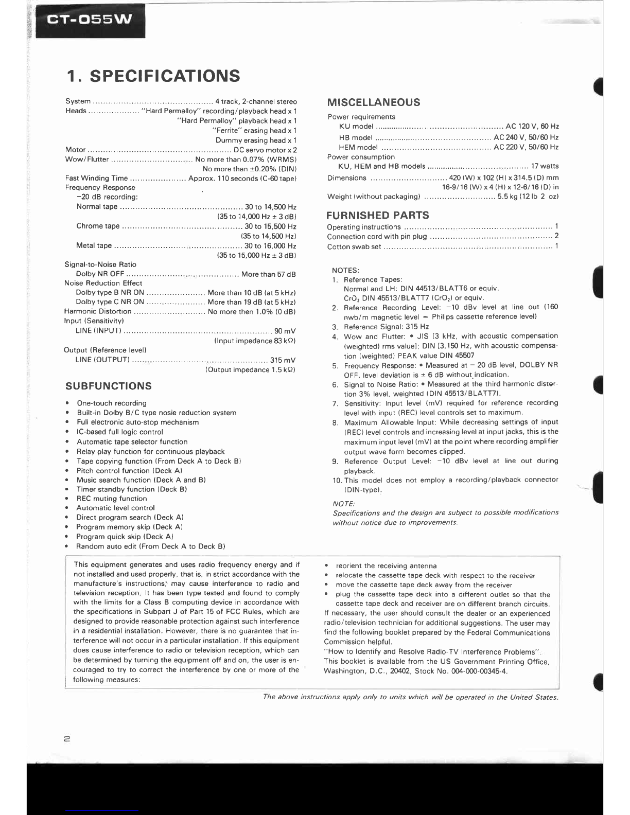
Pioneer CT-055W User manual

0)rrloNeerl"
ORDERNO.
ARP-489-O
STEREO
DOUBLE
CASSETTE
TAPEDECK
Type Voltage Remarks
KU AC12OV
only U.S.A.
model
HEM AC22OV.24OV (switchable) European
continentmodel
HB AC22OV.240V (switchable) United Kingdommodel
o This
service
manual
isapplicable
to the
KU,HEMand
HBtypes.
o Asto theHEM
and
HBtypes
please
referto pages
68 - 70.
o Ce
manual
d'instruction
se
refèreaumodede
réglage,
enfrançais.
o Estemanual
deservicio
trata
del
métodeajuste
escrito
enespafiol.
CONTENTS
SPECIFICATIONS
.
FRONT
PANEL
FACILITIES
BLOCK
DIAGRAM
CIRCUIT
DESCRIPTIONS
. .
DISASSEMBLY
. . .
PARTSLOCATION
EXPLODED
VIEW
AND
PARTS
LIST.......
P.C.
BOARDS
CONNECTION
. .
1.
2.
3.
4.
5.
6.
7.
8.
2
3
5
6
23
25
27
37
g.SCHEMATICDIAGRAM ....43
10.
ELECTRICAL
PARTS
LIST. 47
11.
ADJUSTMENT 50
RÉGLAGE 56
AJUSTE
I2. SAFETY
INFORMATION
. . .
13.SUPPLEMENT
FOR
HEM
AND HBTYPES
62
62
plCfNEEFl ELECTFIGINIC CG'F|PCIFIATICIN 4-1
,Mesuno 1-chore, Mesuno-ku Tokvo 1s3 Japan
PfoNEEFf
ELEcrFoNrcB
ru
sat,t.. is_ "(=%â(
E, \n""TËË?!;
:39_ï:':.="*l " ï
lrfONEEFt ELESTFI6;NIC IEUFIç;PEI w.v. <Ëecoengtaan 1,274o Bevetren, Elelgrum
lEL o3/775eeoa
F|GTNEEF| ELEcTFtcrNtcè augrnÀuta erv. LÏiol lze-le4 Boundany Floacl' Elnaesrde vrctorra 3195 ausc'alra
TEL lo3l sE|o-9911 YZ @ lU
LY. 1984 Prinred
in laPan
MODEL
CT.OssW
COMES
IN THREE
VERSIONS
DISTINGUISHED
AS FOLLOWS:

4. CIRCUIT DESCRIPTIONS
4.1 CONTROL PART
This model carries out all of its controls by the use
of a microcomputer (IC 501). Modes
andprogtams
are selected by the key input supplied into the key
matrix circuit (Fig. 4-4), while the microcomputer
controls various sections such asmechanism drive,
circuit switch'over, and mute control circuits by
feeding command outputs into those circuits' The
display circuit is provided to indicate the music
program beingselected
and REC,DOLBY NR, etc'
being turned on or off.
O POWERON
When the machine is turned on, the built-in micro-
computer is initiatized (Fig. 4-1) and is ready to re'
ceiveinPut sent from the keY.
Wslt for mlcro-
comput€r lCSOt
to 3t6blli26
Chæk to s€ lf decks A and B ar€ in th€ STOP mod€ (thst
15.when th€ hoad bts. is lN) ll thev âro not in ths STOP
mod€, low€r th€ hoâd b63e to put thsm in tho STOP mode
Th61 th€ ba.e is low i3depctêd bv MODE switchôs S3Ot
(for m€chêôi9m on dack A) rnd S4O2 (lo. mschanlsm on
deck B) (Th€ swilch€3 6t€ ofl during the STOP mod€.)
Check 6nd 51or€
the TIMER
RÊC k€Y stôtus in the
RAM is clôot€d
Input and outPUl
ports are sel
limor d6ta la
set
KEY SCAN
Statu3
ol llMÉR
REC koY i3
sto.6d In
thâ m9mory

QUESTIONNAIRE MODEL
OneModel perquestionnaire
DearServicer,
Thankyou for your cooperation
in the post-sale
senrice
of Pioneer
products.
This questionnaireis usedas
atool to improve the serviceability of our products and service
manuals.
Pleaseevaluate this model and servicemanual by answeringthe following questions.Your ideasmay be
realizedin our future products.
Your answers
will beappreciated.
Thank you.
PIONEERELECTRONIC CORP.
T. Nakagawa,
Manager,
Service
Section, lnternational Division
1. SERVICING EVALUATION Circleapplicable
number: Good FaiI Poor
a. Disassembly/Re-assembly:
b. Circuit Checks:
c. Replacement
of Parts:
d. Adjustment (s):
f If (4) or (5) was circled, pleasebe specific.

e. Your advice,opinion or ideas
relatedto senricingthis product.
SERVICE MANUAL EVALUATION
Circuit & Mechanism
Description
b. Circuit Diagram
3. OTHER
Please
describe
other areasof servicing
which you may find difficult.
Completed by :
Company Name :
Address:
CitylStatelZip:
Date:
Please
sendthis form filled to the dittribrtot ir yo.r "outty.

rê
$
1. SPECIFICATIONS
System
.......... 4track,2-channel
stereo
Heads
....................
"Hard
Permalloy"
recording/playbackhead
x 1
"Hard Permalloy"
playback
head
x 1
"Ferrite" erasingheadx 1
Dummyerasing
headx 1
Motor........... .....DC
servomotorx2
Wow/Flutter No morethan
0.07olo
(WRMS)
Nomore
than
+0.20% (DlN)
Fast
WindingTime......................Approx.
110
seconds
(C-60
tape)
Frequency Response
-20 dB recording:
Normal
tape ........
30
to 14,500
Hz
(35
to 14.000
Hz
+ 3dB)
Chromerape............. 30to 15,500Hz
(35
to 14.500
Hz)
Metaltape ..........
30to 16,000Hz
{35
to 15,000
Hz
+ 3dB)
Signal-to-NoiseRatio
DolbyNROFF.............. MorethanSTdB
Noise Reduction Effect
DolbytypeBNRON ...Morethanl0dB(at5kHz)
Dolbytype
CNR
ON ... More
than 19dB (at
5kHz)
Harmonic
Distortion ......... No morethen 1.0olo
(0
dB)
Input(Sensitivity)
LINE
(INPUT) ................,.90
mV
(lnput
impedance
83kQ)
Output (Reference
level)
LINE
(ourPUT)
""' iorrr"i,".,o"o"";;i:;[T
SUBFUNCTIONS
. One-touch recording
. Built-inDolbyB/C type nosiereductionsystem
o Fullelectronicauto-stop mechanism
e lC-based
full logiccontrol
. Automatic tape selector
function
o Relay
play function for continuous playback
o Tape
copying
function
(FromDeckA to Deck B)
. Pitch
control
function
(Deck
A)
o Music
search
function
(Deck
A and B)
r Timer
standbv
function(Deck
B)
o RECmutingfunction
. Automatic levelcontrol
o Direct
program
search
{Deck
A)
. Program
memoryskip{Deck
A)
. Program
quick
skip
(Deck
A)
. Random
aulo edit(From
DeckA to DeckB)
This equipment generatesand uses radio frequency energy and if
not installed
and usedproperly,that is, in stricl accordancewith the
manufacture's instructions; mav cause interference to radio and
television reception lt has been type tested and found to comply
wilh the limitsfor a ClassB computing devicein accordance
with
the specificationsin SubpartJ of Part15
of FCC
Rules,which are
designed
to provide reasonable
protection against
such interference
in a residential
installation.However,thereisno guaranlee
that in-
lerferencewill not occurina particular
installation.lf this
equipment
does cause interferenceto radio or television reception, which can
bedeterminedby turningthe equipment
off andon, the user
is
en-
couraged to try to correct the interference by one or more of the
MISCELLANEOUS
Power requirements
KU model AC 120
V, 60Hz
H
B model ..... AC2'10V. 50/60 Hz
HEMmodel ... AC220V,50/60 Hz
Power consumotion
KU, HEMand
HB mode|s.......,.,, 17wa11s
Dimensions ..........42O
(W)
x 102
(H)
x314.5
(D)
mm
16-9/16
(W)
x4
(H)
x 12-6116
(D)
in
Weight(without
packaging) ........
5.5
k9 l12lb 2 ozl
FURNISHED
PARTS
Operating
instructions .............I
Connection
cord
with
pin
plug ........
2
Cottonswabset............... ........
..'l
NOTES:
1 Reference
Taoes:
Normal
and LH: DIN44513/BLAÏTO
or equrv.
CrO2
DIN
45513/BLATTT{CrO2)
or equiv.
2.
4.
Reference
Recording Level: -10 dBv level at line out (160
nwb/m magnetic level = Philipscassette
reference
level)
ReferenceSignal:
315
Hz
Wow and Flutter:
. JIS 13
kHz, with acousticcompensation
(weighted)
rmsvaluel;
DIN 13,150
Hz,with acouslic
compensa-
tion (weighted)
PEAKvalue
DIN
45507
Frequency
Response:
. Measuredat - 20dB level,DOLBY NR
OFF,
leveldeviation
is+ 6 dB without.indication.
Signal
to NoiseRatio:
. Measuredat the third harmonicdister-
tion3% level,weighted
(DlN 45513/BLATTT).
Sensitivitv: Input level (mV) required for reference recording
levelwith input (REC)
level
controls
setto maximum.
Maximum Allowable
Input: While decreasingsettings
of input
(REC)
levelcontrols
andincreasinglevelat input
jacks,
thisisthe
maximum
input
level
(mV)
at
thepoint
whererecordingamplifier
output wave form becomes clipped.
Reference
Output Level: -'10 dBv level at line out during
playback.
10.This model does not employ a recording/playback
conneclor
(DlN-type).
NOTE:
Specifications and the design are subiect to possible modifications
without notice due to imDrcvements.
. reorientthe receiving
antenna
. relocatethe cassettetape deck with respectto the receiver
. move the cassettetape deck away from the receiver
. plug the cassette tape deck inlo a different outlet so that the
cassettetape deck and receiverareon different branch circuits.
lf necessary,the usershouldconsult
the dealer
or an experienced
radio/television
technicianfor additionalsuggestions.
Theusermay
findthefollowing
booklet
prepared
by the Federal
Communications
Commission
heloful.
"How to ldentify and Resolve
Radio-TV InterterenceProblems"
ïhis bookletis available
from the US GovernmentPrinting
Office,
Washington, O.C
-, 2W2, Stock No. 004-000-00345-4.
5.
R
7.
j followinSmeasures:
The above instructions apply only to units which will be operated in the United States

3. BLOCKDIAGRAM
r
Sl-56
g1-MB
B.
E
FOR MS
crRcurl
s
I
lol ; orr
Eton
MUTING TRANSISTOR
St o"
p,o"
OECK
A
MECHANISM
ASS'Y
DÉCKA
-=
DECK
8
ffi"'flll@p..,,"
ERASE
HEAD

(
@ REC/REC
MUTE
SWTTCH
(. /ol
This switch functions as both the recording switch and record
muting switch. When pressed,
the unit isset to the recordingmode
and when it is kept pressed during recording, it functions as the
recording mute switch.
Recording switch
Press the switch when recording sound onto the tape. The
REC/MUTE indicator
now lights.
lf the accidental
erasure
preven_
tion tabs on the cassette
shellhavebeen brokenout or the taoe has
nol beenloaded,the unit will not besetto the recordingmode even
if thisswitchis pressed.
Press
the STOp switch(rlto release
the
recording
mode..
Recording
mute
switch
When this switch is pressed
during recording,
unrecorded
blanks
can be createdfor as long as the switch is kept pressed.
While kept
pressed,
the REC/MUTE
indicator
willflash
rapidly.
Usethis
switch
for efficient editing of tapeswith sufficient blanksbetween the oro-
grams
and for providing
the unrecorded
blanks
which arereouired
to operatethe music
searchfunction.
This switch does not lock and so functions onty while it is kept in
the prcssed position. When pressed during a recording, no sound
is recorded and so the switch should not be pressed unless ab-
solutelY necessary.
@ T|MER
REC
SWTTCH
This
switchisused
whenan optional
audio
timeris
utilizedfor unat-
tendedrecording.
Timerrecording
isa function
of DECK
B. DECK
A cannot
be used
1or
ttmerrecordtng.
NOTE:
The timer switch should always be in the OFF position when not
performing timet recoding. lf a cassette tape is insened and the
switch is set to the REC position, the unit will automaticalty enter
the recording mode whenever the power switch is turned on.
@ *DOLBY
NR
SWTTCH
{DOLBY
NR
ON/OFF)
Depress
this switch to ON for recording
with the built-inDolby
NoiseReductionsystemand for playback
of tapes
which havebeen
recorded using the Dolby Noise Reduction system.
Fof other tapes, do not pressthis switch.
*Noise reduction manufactured under license from Dolbv
LaboratoriesLicensing
Corporation.
"Dolby" and the double-D symbol are trademarks of Dolby
LaboratoriesLicensing
Corporation.
@ DOLBYB/C SELECTOR
SWTTCH
(DOLBY
NRB/C)
Thisdeckis equipped
with both type B andtype C Dolbynoise
reduction
systems.
AftertheDOLBYNR
ON/OFF
switchis
pressed.
selecttypeBorC
usingthis
switch.TheDolby
indicator
correspon-
ding
to theswitch
position
lights.
@)
COPY
SWITCH
(B
.A)
"Copying" refersto the process of transferring the recorded con-
tents on a pre-recordedtape onto another tape. The pre-recorded
tape is loadedinto Deck A and itscontents are recorded
onto Deck
B. When the switch is pressed,
the REC/MUTE
indicator
will flash
sfowfy. Tape copying cannot be peéormed from Deck g to Deck A.
The playbacktan
loaded into Deck B. When this switch is pressed, Deck A is
automatically
setto the playback
mode
and Deck
B is
automaticallv
set to the recording mode, and the tapes start 10 move
simultaneously.
@ RELAY
PLAY
SWTTCH
(B:Al
Press this switch for relay play. When pressed, the program in-
dicators "1" and "8" will light alternarely.
When the tape loadedin
one deck has
finished
playing
and the tapecomes
to the end, the
tape in the other deck automatically starts playback. Relayplay is
possible
from Deck A to Deck B and vice versa
@ P|TCH
CONTROL
This can be used to vary the tape speed of Deck A acrossa + 60Â
range. The speed increases
when the control is rotated clockwise
( f) ) and reduces when rotated counrerclockwise ( Ô ); rhe
musical intervals
are made higher or lower, respectively.
The stan-
dard
speed
is
obtained
at
thecontrol's
center
clickstop
position
(y).
Usethe control to adjust the speed
when adjustingthe intervals
with
mixingrecording
or playback
orwhen playing
back
a taperecorded
on anothertape
deckon your own deck.
NOTE:
Set this control to the clickstop position (f ) when using the
music search function. lf it isleft rctated clockwise, it will not be
possible to detect the unrecorded blanks between the programs
on the tape during fast forwarding or rewinding operations.
I

t |lul/.:ll|lP
|lakr:sToP
E?f.$i'
.,
,rorI-81
STOP
DECK
A
LINE IN
R/P HEAO
L sl
L
S2
L;;
*-*:t
FOR
US
ciRcutrs2
T
| ---- rl7
'-------------)
"ON" with NORMAL Epe (5304
ând-S305)
'.Ëïr'l *nn a,O, and
METAL tape
(5304and
s305)
ELECTRTC
SWITCH Sl -S6
[6-61
: o"
I:o*
ilU.fING 1RÂNSISTOR
F: o"
' P-t on
LIilE OUT
I *s.su
+ PULL
uP(+l2v)
I
DECK
B
ts
I
LMI --@"'@
,,)t2
n M4
L
M7
TSI
ASOL2
ÀsoL I
I
MUTE BSOL 2
BSOL I
LINE
XUTE KEY
SCAN
coev
,1fl,,
BIAS
ii?. "f3"
Fig,
4-6 Signat
route
1

4.3 SIGNAL
BOUTES
Depending
onthe
modes
selected
ondecks
A and
lf coPY switchis
turned
oN with both decks
A andB in SToP mode,
it causes
decks
A and Bto be
setin pLAy andBEC
moctes
respectively,
resulting
in
different
signalroutes.
DECKA I Oecxe
FF
or
REW
I SfOp
STOP I FF
or
REW
FF I rt
FF REW
REW I rr
MS
Egual
in
starus
toboth
decks
A
and
Bsetin
STOPmode.
Fis.4-5
FUNCTION COPY
SWITCH CONTROL
PARTS
OUTPUT
DECK
ADECK
BS1 S2 53,5554,56 S7 M1 M2,M4 M3 M7
M6
M5
1
2
3
4
5
b
STOP
STOP
PLAY
STOP
STOP
PLAY
STOP
STOP
STOP
PLAY
BEC
REC
OFF
ON
L
H
H
L
H
ll
.I L H roNi L H H ] u H L
. i L H OFFi H L L L H H
LLHONLHLHHL
HLHONLHLHHL
L H L OFF1 H L H H L H
.t
L I H _ L OFFI H L L i H L H

oEcK
a r"n -5?f.$Pt fl
tl
I f'\ r::.:71 t.ffil I
tl.Dec[
Â
:
SIOP
Deck
B
:
STOP
DECK8
t^l
l\-,,1|
lr',1I
lvl
FOR
MS
ctRcutr
s2
tLINE OUT
R
/P HEAO
STOP
LINE IN
Lra
q527
r---- ------]
I S3O4
+F DECK
A I
t.-
i-\---i MEcHaNlsM
rss€ualY I
L---
EL€CÎRIC
SWITGH
SI-S6
16l ; orr
Iton
MUltitG TRANSISTOR
i orr
i ox
1*t.uu
+ PULLuP(+tzv)
F
)
L St
L
s2
t 53
- s5
,,s4
-s6
'""
"'oït
LMI
,,)t2
n M4
LM7
TSI
r2v
q3r
I
^# DEcK
B I
1\?<_--- |
' ' s4o5 rL MEcHaNrsM
aSSEMBLY
i
I
ÀsoL2
ÂsoLI
B-
uuTE B
soL2
BSOL I
coPYH;TÀrx
MUIE / PE --@"*-@
"ON" wilh NOBIVIAL
tâpe
(5304
and5305)
"OFF" with CrO, and
l\4ETAL
tâpe
(5304
and
3305)
Fig.4'6 Signal
route 1

rc
501 rc 502
Fig.4-4 KeyMatrixCircuit
MOOE
5301
ENO
s302
HALF
s303
END
s40
|
MOOE
s402
s
403
aPo
I Pl
cP2
P3
P4
CO
PY
szt8 -
4
s2r8-t
I s2r8-5
$ eur-r-
uP
RESrsroR
os2e (oE:l1l
D2t3 PL^Y
//
o.s.3r
,rr3l"^i; ,or"trIr(
D533 STOP
//
I
I
I

4.2 KEY MATRIX CIRCUIT
The key matrix circuit, composed as in Fig. 4-4,
sends scan pulse to control the mode input for
decks A and B as well asprogram selection input.
The scan
pulsedecodesoutputs from pins L4,75,
and 16 on the microcomputer, sending 10 m sec
pulsefrom pins 1 through 5 of IC 502as shownin
It 5c6ns
th€ k€v oporatlon and
cauæs furctlon æcordlngly.
Fig.4-2.
This pulse, in turn, is fed into one of the pins 17
through 22 of.IC 501 asthe key matrix input cor-
responding to the key input, thus allowing the
microcomputer to send output signals matched
with key inputs to eachsection.
Fig.4-l
I
REC LEO
(O) liOhBup.
Ch€ck to 3@
I' TIMEFI
REC k€y is
ON or OFF Reâdy to rs-
c6iva k€V In-
put
Check tho TIMER REC key
rtats (oN/oFF) slor€d in th€
m€mory, It ON, tho unit 13tn
th€ REC mode
ls FIE
LAY
switch ON?
BAPo Pr P2 P3 P4
ooI L HHHH
oIoFI L HHtl
oI l-l H L HH
o o H H HLH
Iot,a HHHL
Fis.4-2 ControlScan
Pulse Fi9.
4-3

2. COPYswitch
ON
L
52
. s 5
's6
H2
l-1
M7
TSI
FOR
MS
crRcurT
s2
I
ai
)
lZl ; orr
Ito*
MUTINGTRÂNSISTOR
: oFF
i on
I *s
su
Q53/
_.1
|
-,1
_l-J
1
M8
FOR
HEAo+r
st\?ll
oFF 1'
MUTE 8 soL 2
ESOLI
L
iME
MUTE KEY
scÂN
cootnriT*,"
B
IAS
REC REC
MUTE / P8
soLENOr0
DRIVE
ClRCt
rT
KEY
MÂTRIX
CIRCUIT
aà\ ./-\
* fi) oR'ft( )
\-{ \:r/
ON wLIh NORMAL rape rS304 ând5305
OFF w rh CrO: and METAL rdpe rS3O4
dnd S3O5r
Fig.
4-7 Signal
route2

5. DeckA
:STOP Deck
B : REC
LINE OUT
LINE
HM3
LM8
ELECÎRIC
SWITCH
SI-S6
lol : oer
Ito"
HUTING TRANSISTOR
: oFF
i on
I *s.sv
+ PULL
uP(+rzv)
P
)
+
t2v
Q53r
o 527
DECKA Rch- +CtRCUtr
r-t P.8HEAo F
''o,l3l
3il19 ,lÆ
tvt - ,t rh
;br
'f *'
REC
L Si
,,s3
-s5
t-'
FORMS
crRcurrs2 | 1--\ l-:-] r---^ -- !
ll
rJ
I
M8
ASOL2
ASOL I
B ----'
MUTE BSOL
2
BSOL I
LINE
MUTE KEY
SCAN
.ôoY KEY
-- MÂlRtX
MUTE /PA
SOLENOID
ORIVE
CIRCUIT
t----
I S3O4
+B DECK
A i
F\J MEcHANTsMasseàlaLv
I
Y L----- - ------ J
rsz$ DECKI i
, saos
"|' MEcHANtsM
lsseuar-v
!
--@""@
"ON" with NORMAL rape
(5304
and5305)
"OFF" wûh CrO, ànd
METAL râpe
15304
and
5305)
Fig.
4-1O Signal
route
5

3. DeckA:PLAY Deck
B :STOP
(
ELECTRTC
SWTTCH
St-S6
lo3 ; orr
f to"
MUTINGTRÂNSISTOR
D,0,,
)t o"
PULL
UP
(+12V)
aà., /--\
-t5/ o^
tg,)
I
Hst
L::
S4
'' ss
L)
M2
,,Ma
L
uz
TS i
'ON'wrth NORMAL
tape
(5304
and
5305)
'OFF" wrrh
CrOl andMETAL lape
15304and5305)
I t3oo ..g DECKÂ
I r'.- T:::::----r---::---:-----------
|
rl
r-i
I
M8
MUTE A SOL
2
^ ,sol I
MUTE I SOL
2
ESOL
I
LINE
MUTE KEY
SCAN
KEY
'-'' MATRIX
B
IAS
REC REC
lfurE / Pa
XEY
MÂTR
IX
CIRCUIT
-ue , efF
Hus I , I Ic5ol
Fig.
4-B Signal
route
3

4. Deck
A: STOP Deck
B : PLAY
FOR
I,|S
crRcurTs2
T
Lsr
H
sz
. s3
ts5
,,s4
ts6
LMI
,,t 2
n M4
L
M7
TSI
LM8
o52?
r---- -----]
I S3O4 +B DECK A I
+*\J MEcHANTsM assEMBLY I
-@.'@
q3l I
DECK
A Rch +C;RCU;T
u."'8"ë,
D;pr
rr Tst
,r^"8
LINE IN
J-l
"' H :.'-'-i..:^...^^-..^
s4o5 ,ç MECHANTSM
aSSEMBLY
i
L___________-J
"ON" wirh NORMAL tapê
(5304
ândS3OS)
"ôit" *'.n c,o, and METAL rape ls3o4 and 5305)
I *s.su
-çF PULL
uP
(+t2v)
16-îl s orr
A
iIUTE A SOL
g asoL I
MUTE B SOL 2
ESOL I
LINE
ilUÏE XEY
SCAN
KEY
MATRIX
crRcu
|1
Fig.4-9 Signal
route4

6. DeckA:PLAY DeckB:REC
DECKA FORMS
crRcuf
T s
r
P.B HEAO
,,r^"8 h,
OECK
BFOR
MS
crRcurT
s2
T
LM8
o 527
-- R,/p HEAD
-.,tq
lol ; or.
Ito*
tr
lI orr
I otr
I +5 5V
-ç- PULL UP I+ IzV}
HSr
-s5
s4
f M3
I f:--=- [*P--l l-ji,.s,,,RI !
B ÂsoLI
MUTE8soL2
BSOL
J
LIN€
.ôpY KEY
--. . MÂTRIX
E
las
REC REC
I'UTE / PA
r----
i s3o4
.a oEcK
a I
I
1<\_J MEcHANTsM
asseuerv I
/'Al /-\
x ff) on
{*{)
v \:t/
"ON" wtrh NORMAL rape {5304 and 53051
"OFF" wrrh CrO. and METAL taoe (5304 and 5305/
Fig.
4-11 Signal
route
6

No. SYmbol Name vo DEsription
1Vss vs3 GND
RES RES IN Reset
INT INT External interruot/PowER OFF causes
L (This automaticallv leads10STOP mode).
4+5.5V
9X TAL X TAL IN 4.0MHz Crystal resonatot
6EX TAL EX TAL
1NUM NUM GND
ITIMER TIMER Norm€lly at H.
9c0 REC
MUTE
OUT
Deck B Rec mute output, L level
lurns REC mute ON
10 LINE
MUTE Line mute outpul. L lwel turns LINE mute ON.
11 c2 COPY Signalroute change
output. L output during COPY mode; H otherwise.
r2 c3 RÊC INO Oeck B ræording LEO drive oulput *2
r3 uMS Deck A lime constant switch output du,lng music search
H during MS mode.
14 c5
KEY SCAN Cs-C7
ourpût
Po-P4
oulputs
Po Lf---Lf_ rN
PI t_l L_
t' ----l-J- ;;
Pr -----------.1 f- Ds
_uD6
'" --------l_f D?
15
16 c7
17 D7
KEY MATRIX IN
18 D6
1g D5
20 o4
21 D3
22 D2
23 D1 BMS Deck B MS oulse
delætion terminals: deted L MS pules,
24 DO AMS Deck A MS puls delætion te.minâls: detæt L MS pulses.
25 BO MÊMOFY
LEDS
OUT
Memory display LEO d.ive oulput (No.8); L lights up LED. '2
26 B,I MEMORYLED
7Memorv display LED drive outpul lNo. 7); L lighls up LED. '2
27 ,82 MEMOBY
LED
6Memory display LED drive output (No, 6); L lighls up LEO '2
2A D3 MEMOFY
LED5 Momory display LED drive output (No, 5l; L lights up LED '2
29 B4 MEMOFIY LED 4Memory display LED driv€ output (No 4); L lights up LED '2
30 B5 MEMOFY LEO 3 Memo,y display LED d.ive output (No 3); L lights up LED. '2
31 B6 MEMORYLED2 Memory disptay LEO drivo output (No. 2); L lighrs up LEO. *2
32 87 MEMORYLED
1Memory disptay LED drive output (No. 1); L lighls up LED '2
33 AO BIAS Deck B bias
OSC ON/OFF output: L lturing REC mode.
gA1 REC
/ PB Deck B BËC/PB switch-overoutput: H during REC mode.
35 A2 B MUTE Deck B signal route switch.over: L during PLAY on Deck B
36 A3 A MUTE Deck A signal
roule swilch-over: L during PLAY/COPY on Oeck A.
A4 ASOL2 Osck A Solenoid-2drive pulse
output: L activated.
38 A5 A SOLl Deck A Soleooid-l drive pulse
output: L activ€ted.
39 A6 B SOL2 Oæk B Solenoid"2 drive pulse slput: L activaled.
40 A7 B SOLl Dæk B Solenoid-l driva pulF outpul: L activated.
o lC TECHNICAL DATA
PD3012
l--------l[ T,ansisto,s*itch
fll Læt.*itcn
fiTaotuat switch
Output
timing
LEO lighted
LED tlashingslowly
LED tlashingfa$ly
Fig.4-14

6. DeckA:PLAY DeckB:REC
FOR
MS
crRcurT
sl
"aOrE
OECKS
I
MUTING
\J}
)
lol ; o.r
:oN
TRAI{SISTOR
I orr
i on
Â
I +55V
-E- PULL
Up
(+
12v)
Hsr
M2
- M4
H t47
TSI
rs2
FOR
HEAD
OFF
Hvr
z\-
ï
T---
I S3O4
râ DECK
aI
FORMS
crRcurT
s2 I f-=- f,;;--l l- oo.,'-G__.lI
rl
_l
tl
-lJ
I
I,IUTE Â SOL 2
^ ÂsoL I
MUTE BSOL2
85oL I
LINE
HUTE KEY
SCA
N
coPY
uiià't
8
rÂs
REC REC
MUTE / PB
DECK A
OECX B
lus *---I---------d rcsol aà /-1\
' {+](,J on {*{)
\-{ \:t/
"ON w,lh NORMAL tape (5304 ànd 5305)
OFF wrth CrO: and METAL tape lS3O4
and 53051
Fig.
4-l1 Signal
route
6

4.4 DIRECT MUSIC
SEARCH
For direct search,
the tapeisfirst rewound comple-
tely in RE\{ mode. \ryith one of the searchkeys de-
pressed,the tape is then fast-forwarded to the be-
ginning of the program desired (the intervals be-
tweenprograms
arecounted during FF mode).
When the beginning of the wanted program is
reached, the tape is set in the STANDBY mode.
Depressing the PLAY key allows the program to
start. In this way, the desiredprogxamis automati-
cally located for playback by depressing
the pro-
gramNo. key.
The direct music searchmode allows desired
pro-
grams to be played back in a desired sequence
re-
gardlessof the order in which the proglams lvere
originally recorded (for the first program to be
playedback,tapeisrewound until the beginningof
the tape is reached; from the second progmm on-
ward, direct search takes place). Moreover, the
sarne
prograrn can beplayed back asmany times as
the prognm No. key isrepeatedly
depressed
(up to
16 times). When used for copying, this mode en-
ables the desired number of progxams
on the o-
riginal tape to be dubbed in any desiredsequence.
During copying, the non-recorded
sections
between
the programs being dubbed are automatically ad-
justed for a uniform interval (automatic random
editing).
4.5 MODE CHANGE IN THE MECHANICAL
SECTION
The mode selection for the mechanicalsection is
controlled by the output (pins 37 through 40)
from the microcomputer (IC 501) corresponding
to the key input. The output from the microcom-
puter turns on and off SOL 1 and SOL 2 of the
mechanical section, which trigger mode changes
with the po\Merassistmechanism using the rotar5l
power of the capstanmotor. The mechanical
sec-
tion changesits mode as shown in the Fig. 4-13,
and this always via the stop mode. The timing
chart in Fig. 4-15 shows the control signals for
different modessentfrom the microcomputer.
Other manuals for CT-055W
1
Table of contents
Other Pioneer Tape Deck manuals

Pioneer
Pioneer CT-970 User manual

Pioneer
Pioneer T-6600/F User manual

Pioneer
Pioneer CT-8R User manual

Pioneer
Pioneer PRV-LX1 User manual

Pioneer
Pioneer RT-1011L User manual

Pioneer
Pioneer CT-F615 User manual

Pioneer
Pioneer RT-1020L User manual

Pioneer
Pioneer CT-730 User manual

Pioneer
Pioneer CT-40 User manual

Pioneer
Pioneer CT-F615 User manual

Pioneer
Pioneer CT1270WR User manual

Pioneer
Pioneer CT-1060W User manual

Pioneer
Pioneer CT-970 User manual

Pioneer
Pioneer CT-1150R User manual

Pioneer
Pioneer CT-4 User manual

Pioneer
Pioneer CT-F600 User manual

Pioneer
Pioneer D-07 User manual

Pioneer
Pioneer CT-3131 User manual

Pioneer
Pioneer CT-1060W User manual

Pioneer
Pioneer CT-W802R User manual