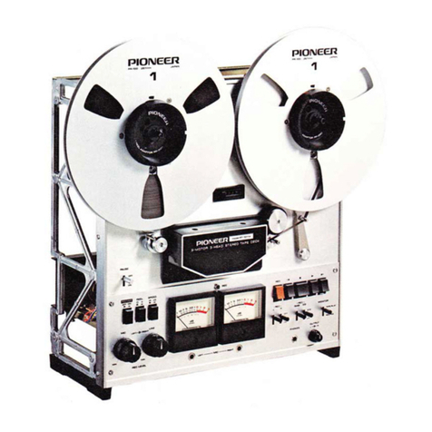
Pioneer RT-1011L User manual

<ART-076-0>
WICEMANUAf,
STEREO TAPE DECK
FITIIOIIL
KU, FV
<74G02Y31 K> (DriDtoNEEFt'


through R613 - RL602 - relay con-
tact RL601 - S11-2 - 510-2. This
causes RL602,to operate.
Two motors T.M and S.M are ener,
gized through the contacts RL602-1
and RL602-2 of RL602 to give
take-up torque and back tension.
RL603: Operates at FAST FORWARD, RE:
WIND and STOP.
When the shut-off switch (S1b) is ON
at STOP, current flows through
R614 - RL603 N relay contact
RL601 - S11-2 - S10-t, causing
RL603 to operate. The series resistl
ance R3 of T.M is short.circuited by
the contact of RL603.
o Control Circuit for Solenoid Sup-
ply Voltase (Fig. 5)
This circuit operates to prevent overheating
from continuous operation of the solenoid,
thereby dropping the current to that.required
to hold it ON. In Fig. 5, Q1, Q602, and
ZD6OI from a voltage stabilization cireuit
supplying the retaining current for continuous
operation of the brake solenoids (SL1, SL2)
and the pinch roller solenoid (SL3).
When the PLAY button is pressed,Sl2 changes
over to the PALY position, and a closed loop is
formed by the power supply (*) - Q1 : (SLB
N D610) / (SL2 - SL1 ry D609) ry relay
contacts'(RL601) - S11-2 (REW button) S10-2
(F.F. button) r power supply (-).
Q1 and Q602 are Darlington conneeted, and
between. the base and collector of QG02 is
capacitor C62\.
Immediately after the PLAY button is pushed,
much charging eurrent flows rapidly into C621
via power supply voltage(+) - C621- R616 -
Q602 in that order, and then the current that
flows into Q1 increases. causing the solenoids
to operate.
When C621 is completely eharged, Q602 bias
becomes cbnstant UV nOi5 and ZD6O7 and the
cirrrent that . flows into Q1 decreases into
holding the continuous operation of solenoids
oN.
. .Take-up Torque Control in
PLAYBACK (Fis. 6,71
In order to.prevent tape slackening or hunting
when switching foim the STOP mode to
PLAYBACK, the take-up torque is Subject to
initially reinforcement.
1. When the tape deck is in the STOP mode
(that is with no function button de-
pressed).
relay RL603 is operative, and the relay
contacts short-circuit the series resistor
(RB) of the take-up motor (T.M). Please
" refer to "Relay operation.?'.
2. When the PLAY button is depressed, 512-1
goes over to PLAY, the current from the
FIT-1 cl1 1 L
power supply to RLG03 is,cut off, and
current flows to RL602
Even after the current has beeh cut off,
RL603 continues to hold. on briefly by
means ctf the charge on C620 in parallel
with it before releasing.
This ensures that when the take-up motor
is switched oo, the series resisttr (RB)
remains ineffective, increasing the initial
torque.
As soon' as. RL603' releasing the current
flows through R3, and the torqug Drops to
the normal level.
3.
4.
Sro-z )rz-t Fis. 5
Fig. 6
Fig. 7
9

o Tape Protection at PLAYBACK
lmmediately From F.F. (or REW)
( Fig. 8)
If the PLAY button is pressed while the deck is
in the FAS1' FORWARD (or REWIND) mode,
the tape is brought to a halt briefly before
resuming travel at the specified speed, in order
to protect it.
As shown by Fig. 8. the circuit is structured
mainly around Q603 and Q604.
1. The base of Q604 is biased via R60? -
R606 - D606 - 510-2 (S11-2) while the
deck is in the FAST FORWARD (or
REWIND) mode. Q604 is thus ON and
relay RL601 is operative.
2. The base of Q603 is connected via R610 to
the collector of Q004. When e604 is ON,
the base of QG0B is reverse biased, and
Q603 is OFF.
3. C619 is charged via R604 (C618) - C619
- R606 - D606 - 510-2 (S1L-2).
4. When the PLAY button is pressed, 512-1
goes over to PLAY, S10-2 (S11-2) return
to their OFF positions, and the base bias
loop for Q604 (in step 1. above) is broken.
The charge accumulated in C61g, however.
Forms the base current of e604 and keeps
it on maintining the relay RL601 opera-
tive.
5. Even if 512-1 goes over to pLAy, while the
relay RL601 is operative, its relay contacts
(RL601) will not cause RL602 to operate.
6. As C619 discharges, so the base current of
Q604 drops, with a corresponding increase
in its internal resistance, and agreater
potential difference between the emitter
and collector.
7. When this potential difference reaches BV,
the reverse bias which had been applied to
Q603 becomes direct bias, urrd e603
comes ON.
8. When Q60B comes ON, C61g is rapidly
discharged via D60b - R60b - eOOg,
Q604 goes OFF, and the relay RL601
releases.
9. As soon as relay RL601 releases, a current
flows through R613 - RL602 N relay
contacts (RL601) - 51'J.-2 - 510-2, caus-
ing relay RL602 to operate so that the tape
commences to travel at the specified speed.
10. C619 is fully charged after some 6 seconds
of FAST FORWARD (or rewind), and it
takes about 6 or 7 seconds after the PLAY
button is pressed before the specified speed
of tape travel commences.
11. R604 serrres to delay the charging of C61g
and D605 does to accelerate its discharge.
If, therefore, the PLAY button is pressed
after only from 0.5 to 6 seconds of FAST
FORWARD or REWIND CG19 wilt not be
fully charged, the time taken for it to
discharge (that is during which Q604 will
remain ON), and the pause before the tape
commences travel at the specified speed
will be correspondingly shortened.
The Function of C618
Such delay circuit as shown in Fig g would
not protect the tape on those occasions when
the length of FAST FORWARD (or REWIND)
operation is so short - 0.5 seconds or less -
that the tape would not come to a complete
halt before attempting to commence travel at
the specified speed after pressiirg the PLAy
button. If not prevented, this would cause the
tape stretch or snap. This possibility arises
because of the inadequate charge in C619 due
to the very short time during which the tape
deck is in the FAST FORWARD or REWIND
mode. In order to prevent it the circuit shown
in Fig. 10, incorporating C61g was added. The
addition of C618 and R604 prevents the delay
in the charging of C619 and provides sufficient
voltage to hold Q604 ON instantaneously.
Fis.9 Fig. '10
umbers indicate each of characteristics:
O C619 onty
@ when C618 is incorporated (Fig.1g)
@ when R604 is incorporated (Fig.g)
Voltage necessary
to hold 0604 ON
Reoe I Rsto.
EW
Sro-z Srr- z
Fis. 8-_; tFis. 11

3.5 PAUSE ClRcUlT (Fig. 12)
When the PAUSE switch (S6) is turned ON in
ihe PLAY and REC modes, the base of Q604 is
biased via R608 - D612 - 56 - 512-7 - S11-2
- S10-2 to switch Q604 ON, causing RLG01 to
operate. Because of this, the contact of RL601
is closed to operate RL603. This also makes
solenoids SL1, SL2 and SLg non-operative.
Further, RL602 restored and, through its
contacts (RL602-1, RL602-2), shuts off the
power to T.M and S.M stopping these motors.
When the PAUSE switch is turned OFF, the
bias to Q604 is cut off and relay RL601
restores. Its contact is opened. But RL603
remains operative until C620 completes dis-
charging, improving the take-up torque at the
beginning of tape transport.
Reduction of waiting time lag by use of PAUSE
switch. When the Fast Forward or Rewind
modes continue for more than 6 seconds, CG19
is charged. The deck needs 6 - 7 seconds to
start playing when the PLAY button is pressed.
This time lag can be shortened using the
PAUSE switch.
1. QGOa is ON in the F.F. and REW modes.
2. The base of Q603 is connected to the
collector of Q604 via R610. When Q604 is
ON, Q603 is OFF.
3. C619 is charged via R604(C618) - C61g -
R606 - D606 - S11-2 - 510-2.
4. When the PLAY button is pressed, C619
stops charging and discharges via C619 -
D605 - R611 - Q604 - R607 to produce
Q604's base bias current, keeping Q604 ON
for serveral seconds.
5. When the PAUSE switch is ON, Q603 is
forward biased to ON via R609 ry SG -
S12-1 - S1L-2 - S10-2 and, C619 is rapidly
discharged through the loop C619 - D605 -
R605 - Q603.
FIT-1 01 1L
6. When the PAUSE switch is OFF, the bias
loop R608 - D612 - 56 - 512-1" - S17_-I -
S10-2 is cut off to turn QG04 OFF. This
restores RL601 and operates RL602, start-
ing tape transport.
3.6 FUNCTION BUTTONS RELEASE
clRcUlT (Fig. 13)
When the tape has shut-off switch (S1b) goes
'OFF', and solenoid SL601 operates to release
the function button.
1. S15 goes ON when the tape is properly
loaded, and feeds the AC supply to the
circuit.
2. The base of Q601 is subject to reverse bias
via D603 and Q601 is thus OFF, C61? is
also charged via D604.
3. When the tape has been fully taken up and
S15 goes OFF, no negative voltage from
D603 comes supplied, and the charge ac-
cumulated on C6LZ positively biases Q601
via R603, so that Q601 goes ON, and C61?
discharges via SL601 - Q601.
4. This discharge is the means by which the
release solenoid operates, so releasing the
function button which has been depressed.
5. This circuit, if S15 is ON will operate if the
power supply is interrupted, and automati-
cally release the function button.
Fis. 13
3.7 TAPE SPEED SWITCHING.OVER
The capstan motor is a hysteresis synchronous
type, operates at the main power supply
frequency. Speed switching is effected by
altering the number of poles by means of the
SPEED SELECTOR switch S8
19 cm/s(7-1l2 ips.) 4 poles
9.5cm/s(3-3/4 ips.) 8 poles
2SA6?2 tB)x2
11
Fig. 12

4. DISASSEMBLY
4.1 BACK coVERS (Fig. ta)
1. Take out screws 1, 2, b and Z, but only
loosen screws 8,4 and 6. Remove the back
cover (A).
This exposes the internal mechanism and
permits examination.
2. Take out screws 8
back cover (B).
The amplifiers can 2
3@\
4
gDEt-:''
BOARD
4.2 SIDE BOARDS
Take out screws 1 - 8
boards.
(Fig. 15)
and remove the side-
-L3
then
and iemove
be adjusted.
Lo<isen scr.an/s.
w
'V/, BoARD
{a, ,/
i 'w/
T2 Fis. 15

4.3 AMPLIFIER PANEL (Fig. 16)
1. Remove all knobs.
2. Take out screws 1 - 4 and remove the
the amplifier panel.
The level meters can then be replaced.
FIT-1 c'11 L
MECHANICAL PANEL (Fig. 17)
Take out screws L - 2 and remove the
head housing.
Take out screw B and remove pinch
roller.
Take out screws 4 - 6 and remove the
reel base.
Take out screws 7 - g and. remove
the guide roller.
Take out screw 10 and remove the
tension arm.
Remove the PAUSE knob.
Take out screws 12 - 1.7 and remove
the mechanical panel by lifting out the
aluminum sashes.
Take out shaft cap.
4.4
1.
,
3.
+
5.
N3
t-b\
Fig. t 6

5. TROUBLE SHOOTING
5.1 TRANSPORT MECHANISM AND CONTROL
"Reel motou" refers to the take-up and supply motors. For
Nos. 1 - 5.
SYSTEM (1).
further explanation, see section 5.2,
r Power supply
Lack of Power ON,
and lamps.
See 5.2.1 "Power and lamps."
See 5.2.1 "Power andlamps."
Improperly positioned REEL.-.--...- f,e11sct position to match reel size.
size switch.
Ttonble in reel motors. 'See 5.2.2 "Reel motors."
Lamp does not light.
See 5.2,3 "Pinch roller."
See 5.2.3 "Pinch roller."
{e-adjust. See section 6.3.
See.5.2.4 "Capstan motor."
Tape slaekens at
start of tape travef.
(Supply side)
Tape squeals.
Excessive back tension
uble in capstan motor.-
Abnormal take-uP torque.-
Relay RL603 released sal[is1. -
Poor back tension.
Soiled tape guide
Clean with absolute alcohol.
See 5.2.3 "Pinch r6ller."
See 5-2.3 "Pinch roller,"
I,ubricate, clean or replace where
necessary.
Re-adjust. See section 6.3.
See 5.2.4 "Capstan.motor."
See 5.2.2 'Reel motor."
Replace capacitot (C 620).
See 5.2.2 "Reel motor."
Clean with absolute alcohol.
Replace.
(Take-up side)
Control system does -------Burned-out fuse (F 5). Replace.
not function LDefective shut-off switch.- Replace.
o Playback function.
Take-up too weak or ----T
too strong. I
t
Insufficient tape speed. Pinch roller slipping.
Poor pinen- roller pressu
Excessive back tension
Poor capstan motor torque'.-
Defective tlpe speed-Defective switch (S 8).--------------- Replaie.
switching.
Wow and flutter; Dust on pinch roller and +
capstan.
Defective pinch roller. .
-
Poor pinch roller pressu.re.
--
Excessive friction or sticking
-
of flywheel bearing.
l4
Damaged tape.

FrT-1 cl11 L
o Fast forward and rewind.
Take-up delayed until--;Poor take-up motor torque..-.'- .- See 5.2.2 "Reel motors."
end of tape travel' LE*""r.iu. back tension see 5.2.2 .,Reel motors.,,
Tighten or loosen tape -Abnormal back
winding. tension.-- Re-adjust. See section 6.3
Tape slackens at stop
of the tape.
Mechanical noise
operation.
Difference in sizes of
and left reels"
Brake timing trouble
adjustment.
right-- Match reel sizes properly.
or mal- - See 5.2.5 "Brake."
during-t-Defective
LDefective reel motors. Replace.
guide roller. Replace.
Short interval-time- Defective capacitors Replace.
between fast forward (C618, C619)
or rewind to play.
5.2
1.
Lack
TRANSPORT MECHANISM AND CONTROL
Power and lamps. SYSTEM (2l'.
Replace.
Replace.
Replace.
Replace.
of power input;-------1-*
t
I
Burned-out fuse.
Defective AC cord-
Power switch failure.
Defective power transformer
Meter lamp does not -----lDefective lamp.
light' LB.,r.ed-out fuse
Replace.
Replace.
15

2. Reel motors check to make sure line frequency switch is in proper position.
Defective ph ase capacitor.-
stuck motor shaft._
Defective motor coil.-.--
Brake does not clearanc
Defective wire wound resistor--
(R3orR4).
Defective relay contact or -=-
relay (RL 602).
Imperfect FUNCTION
button contact.
Replace.
Replace the motor.
Replace the motor.
Re-adjust. See section 6.2.
Replace..
Replace
Replace.
No back tension Defective wire wound resistor_ Replace.
in playback mode. (R 2).
Re-adjust. See section 6.3.
Replace.
Replace.
3. Pinch roller AIso check sotenoid (SL 3).
Revolving sound squeaks.- Stuck bearing.
Dull rotation, Stuck bearing excessive
friction.
Pinch roller slipping.- Dirty pinch roller.
Clean and lubricate.
Clean or replace bearing, then
Iubricate.
Clean with absolute alcohol.
Defective control circuit.- Check circuit and make necesFary
repairs.
Worn-out solenoid shaft- Replace the solenoid
No voltage to motor.l Defective shut-off switch contact.- Replace.
L-Burned-out fuse (F6 or F7)-Replace
Motor failure despite
apparent vol[age.
Defective take-up at
playback mode.
Defective fast forward.---1-Excessive back tension.- Re-adjust. See section 6.3.
I
L.- FUNCTION button contact
-
Replace.
Defective rewind.
No back tension in_-
fast forward mode.
failure.
Excessive babk tension._ -..-
Poor FUNCTION button_
contact.
Defective wire wound lssislel _
(R 1).
R""ttr *: solenoid --1 Def ec tive transistors ( e 1, e 60 2 ).- Replace.
i - Defective diode (D610 Replace.
toK
-""1
Insufficbnt attracting---1-- Imperfect solenoid installation.- Re-adjust. See section 6.4.
force.
16

FtT-1 01 1 L
is properly positioned.
4. Capstan motor
No voltage to motor.----i*Defect
" lo* L
,f
Motqr does not rotate
1'l
]"" t
6. Function button.
Button fails to snap back-Stuck button.
Check to see that Iine
shut-off switch contact.
l* r*,r"^ contact welded.-
l- Switch lock plate caught.--
Re-adjust. See section 6.2
Repair.
Replace switch.
Replace switch.
frequency switch
- Replace.
ut fuse (F6) Replace
Defective phase capacitor.- Replace.
Motor shaft friction, Lubricate.
Replace the motor.
Replace the motor.
Stuck motor shaft'
Defective motor coil,
Also check brake solenoids (SL1, SL2).
----r-Defective transistors (Q1, Q602).- Replace.
l'"'
I Defective diode (D608,D600 ;.- Replace.
I
- Improper adjustment Re-adjust. See section 6.2
lnsufficient torque.- Defective phase capacitor.- Replace.
5. Brake
Brake release failure
I
I
I
lox
I
Insuff icient brake ----; Improper solen oid installation.- Re-adjust.
solenoid attractins I -
force. I IDefective control circuit.- Check circuit and make necessary
I o* | rePairs'
l"^ Lworn-out Solenoid shaft- Replace the solenoid
Brake mechanism does-Btake spring not in place =_- Hogk spring in place
not function
Improper brake frictionl DustV or soiled brake drum. Clean with absolute alcohol.
L- Improper adjustment
Button fails to snap
back at shut-off or
power OFF.
Defective capacitor (C61 7 ).-- Replace.
Defective reset solenoid (SL601)- Replace.
Reset plate caught. Replace.
5.3 ELECTRONIC CIRCUIT TROUBLE
r No playback sound.
Connection cord check- Defective connection cord
-
Reconnect.
contact.
Defective playback head.-- Replace.
Power supply circuit check. Repair or replace.
Defective P.B. amplifier circuit.- Repair or replace.
Loose connection of internal- Repair.
connection cord.
l7

o lnsufficient sound.
Clean head.
. Sound distortion.
OK
T\rrn output level down. -Excessive connected
. Poor treble.
Clean head.
o Poor bass.
Change tape:
o Sound
CIean head.
I
drop-out.
NG
Worn-out head.
Defective semi_fixed resistors -- Replace.
(vRs - VR8).
Defective P.B. amplifier circuit.-.Replace or repair.
Clean with absolute alcqhol.
Replace.
amplifier - Lower input level.
input.
Excessive recording level.--- Lower recording level.
Defective tape use.
Low power supply Change tape.
voltage ---- Cheak power circuit.
Clean with absolute alcohol.
Improper head azimuth.- Re-adjust. See section ?.
Defective equalizer circuit.- Re-adjust. See section 8.2.
Worn-out head. Replace..
Defective resistors (R2n Replaee.
R222).
Defective coupling capacitor.- Replace.
Clean with absolute alcohol
Defective or worn-out tape- Change tape.
or occasional noise.
Defective transistors
(Q201 - Q204). Replace.
Defective resistors (R201 Replace.
R202, R209, R210).
Defective capacitors Replace.
(c205, c206).
Poor soldering contact. Check and repair.
.Ex
Shake
l-*.
I
I
l*"
cessive
deck.
change..
18
lse-

equipment.
FIT-1 C]1 1 L
o Excessive hum.
Check innut jacks.----1-Defective power supply circuit.- Check and repair.
i - _ _ -Couple leakage flux from
NG
Repair jack or connection.
o Recording impossibte - Playback possible.
Check connection cord - Poor cord connection, Reconnect.
and jacks.
I
loK
Check oscillator circuit. -Defective REC amplifier circuit.-
NG
o Poor recording treble, playback treble.
Clean head.
bias current
Repair or replace.
Repair or replace.
Clean with absolute alcohol.
Re-adjust. See section 8.6.
I
i. Excessive
o Recorded sound insufficient or distorted.
Clean head.
Improper bias current
Defective capacitor
(c418, C419).
Defeetive semi-fixed resistors _
(VRaO1;VR402).
Defective oscillator circuit.- Check and repair.
Clean with absolute alcohol.
Re-adjust. See section 8.6.
Replace.
Replace.
o Erasing
Clean erase
does not take place.
head. Clean with absolute alcohol.
Defective level meter. Replace.
Replace.
Defective semi-fixed
resistors (VR404, VR405).
Defective diodes (D407, D408).- Replace.
Tape running interference.-Check and repair.
Incorrect head height Re-adjust. See section
L--------t-De f ec t ive oscill ato r c i rcu it.- Ch eck an d rep air.
NGI LDefective erase head. Replace.
I lmpaired level meter function.
o Excessive crosstalk.
7.
19

6. MECHANICAL ADJUSTMENTS
For items 6.1 - 6.4 adjustments, nev"er fail to
place the tape deck in specified positions (6.L:
horizontal, 6.2 - 6.4: vertical); otherwise,
correct measuring value would nbt be obtained.
With these things in mind, proceed ai follows:
6.1 REEL BASE HEIGHT
ADJUSTM ENT
In the case of incorrect reel base height, or
replacement of supply motor or take-up motor,
sideboards are removed and reel base height
must be adjusted.
1. Place the tape deck in a horizo5rtal
position and check to make sure the
panel and chassis of the transpbrt
mechanism are firmly attached.
2. Loosen screw to allow a clearance of
8.5mm between the mech panel and reel
base as in Fig. 18.
3. Adjust supply and take-up reel bases as
above.
6.2 BRAKE ADJUSTMENT
Required when tape slackerx or when sol'enoid
or motor is replaced.
First, place.the tape deck in a vertical position'
and check the following:
o Is A in Fig. 19 t2.8mm when the solenoirl
is not :operatirrg?
o Can you rotate the motor
your hand while, pressing
shaft?
smoothly with
the solenoid
o Adjustment (Figs. 19 , 20l.
For adjubting the take-up reel, fast-forward
it for about 2sec.'once to minimize unstableness
in measuring values, then push the STOP
bu.tton to'cause reel revolution to halt.
Should the reel be'rotated before measuring,
differences in measurihg values would result.
For adjusting the Supply reel, rewind it once,
then make the adjustment.
These adjustments are made in (A) N (D)
arrow-indicated directions.
With these things in mind, proceed as Tollows:
1. Load the ?-inch reel, fixing the string on
the reel base.
2. Pnll tension gauge to measure brake friction,
pulling in B (C) direction until reel turns.
3. Adjust the brake spring hook position so
that the gauge reads 300 - 4509 (900 -
1350g-cm).
4. When the above adjustments fail to bring
the desired results, check the following
points:
o Soiled brake drum
O Soiled brake felt
o Faulty brake guide plate
o Unstable brake arm
5. Measure brake friction by pulling tension
gauge in D (A) direction.
Then, check ratio of brake friction to
measured value of step 3. It should be
2.3:1-3.7:1.
NOTE:
When the value in B (C) direction indicates
4009, the value in D (A) direction is
optimum at a range of 174 - 1089.
BRAKE SPRING
BFTAKE GUIDE
PLATE
-l To attach the brake drum in
position f irmly, gradual ly
tighten the two setscrews
1, 2 alternately.
After making
adjustment, fasten
firmly (more than 10kg'cm).
Cha nge spring
hook position.
6tu\\
fo\t\D R U M
,Y, )I
SCREWS
20
12.8mm

o Conf irmation After Adjustment
1. When the prior adjustment is over, lower
lOVo power source voltage (down to 10gV
in 120V area, for example) in order to check
up on fast-forward or rewind operation with
the help of a lO-inch metal reel (long tape
t50vo).
2. While transporting the tape reels at high
speed, push the PLAY button when the tape
volume being now taken up in the take-up
reel becomes increased more than that of
the supply reel - when you see the taken-up
volume show about 10 - 40 m/m
3. Confirm that the tape speed runs normal
after it stops completely.
4. If the specified condition in step B is found
unsatisfactory, try to satisfy step g
repeatedly even though a tension gauge
does not read less than 3009.cm.
NOTE: C618 and bOf g short of capacitance
make condition in step B unsatis-
factory.
6.3 TAKE.UP AND BACK TENSION
TOROUE ADJUSTMENT
. Back Tension Torque at Playback
(Figs. 20 ,211
1. Set REEL size switch at 10-inch reel
position.
2. Set tape deck in vertical position in playback
mode at 1-tlZ ips (19cm/s).
'Measure back tension of supply reel base
by pulling tension gauge in B direction
as showa in Fig. 20.
FIT-1 cl11L
3. Adjust slider (R2 500O) so that the gauge
reads 93 - 110g (280 - 330g.cm) (Fig. 21).
4. Set REEL size switch at 7-inch reel position.
Measure back tension as mentioned in step 2.
5. Adjust slider (Ra 100Q) so that the gauge
reads 63 N 77g (l-90 - 230g.cm).
6. After adjustment, the slider serew must be
firmly clamped.
o Take-up Torque at PlaYback
(Figs. 20,2U
1. Set REEL size switch at 10-inch reel
position.
2. Set tape deck in vertical position and in
playback mode at 7']-12 ips (19cm/s).
Measure take-up torque of take-up reel base
(While moving tension gauge slowly in C'
direction as shown in Fig.lQ, read value of
the gauge.)
3. Adjuit Jtider (R3 300Q) so that the gauge
reads 190 N 21Ag (570 N 630g'cm).
. Back Tension Torque at Fast Forward
( F igs. 20 ,21l,
1. Set reel size switch at 10 in. reel position.
2. Set tape deck in vertical position in fast
forward mode.
Measure back tension of supply reel base
(pull in B direction as shown in Fig. 20 ).
3. Adjust the slider (Rf 2kSl) so that the
gauge reads 35 - 45g (105 - 135g-cm).
NOTE:
When back tension of fast forward is
adjusted, back tension of rewind is deter-
mined automatically, since the resistor R1
is used for both functions.
Fis. 21
21
(6ommoffi
;;;; SLIDER
Loosen Clamping
Screw and adiust.
Fis.2O

6.4 PINCH ROLLER PRESSURE
ADJUSTM ENT (Figs. 22, 23l,
When replacing pinch roller solenoid or pinch
roller, checlr pressure of capstan a.s follows:
1. Set tape deck in vertical position with
REEL size switch at 1O-inch reel position.
2. Turn POWER switch and shut-off switch
oN.
Set deck in playback mode.
3. Make sure that the gap B shown in Fig.
22 is Lmm.
4. If the value is not correct, loosen the
three bracket-held screws and adjust
position of pinch roller solenoid.
B= 1mm
screws and adjust position.
Fis.zz
Load Scotch No. 111, L0-inch metal
reel (or similar product). Run tape fast
forward until amount on take-up reel
matches that on supply reel.
Play tape at constant speed (7-Il2 ips)
hook tension gauge as in Fig. 28, then
pull the gauge, and confirm the value
when travel is stopped in 1.Tkg - 2kg
range.
When tape traveling is not stopped with
in L.7kg - Zkg, check the following:
a Loosen pressure spring fastening
o Defective pinch pressure spring
o Soiled pinch roller
o Soiled capstan
5.
6.
7.
PINCH FTOLLER
SOLENOID
BRACKET
Remove
Pull tension
INCH ROLLER
CAPSTAN
,t Fig.zg
Other manuals for RT-1011L
2
Table of contents
Other Pioneer Tape Deck manuals

Pioneer
Pioneer CT-4 User manual

Pioneer
Pioneer CT-1060W User manual

Pioneer
Pioneer CT-F2121 User manual

Pioneer
Pioneer CT-F9191 User manual

Pioneer
Pioneer CT-W704RS User manual

Pioneer
Pioneer CT-8R User manual

Pioneer
Pioneer RT-1011L User manual

Pioneer
Pioneer CT-506 User manual

Pioneer
Pioneer CT-970 User manual

Pioneer
Pioneer CT-50R User manual

Pioneer
Pioneer CT-200 User manual

Pioneer
Pioneer CT-5 User manual

Pioneer
Pioneer CT-A9X User manual

Pioneer
Pioneer CT-F9191 User manual

Pioneer
Pioneer CT-70R User manual

Pioneer
Pioneer CT-A9 User manual

Pioneer
Pioneer RT-909 User manual

Pioneer
Pioneer CT-970 User manual

Pioneer
Pioneer CT-F900 User manual

Pioneer
Pioneer CT-740 User manual