manuals.online logo
Brands
  1. Home
  2. •
  3. Brands
  4. •
  5. Pioneer
  6. •
  7. Turntable
  8. •
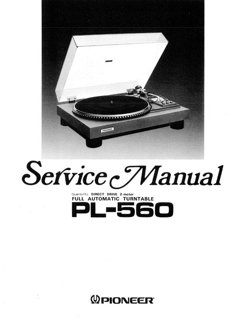
  9. Pioneer PL-560 User manual

Pioneer PL-560 User manual

Service
PALEY
INTEN
CIRCUIT
&
MECHANISM
DESCRIPTIONS
ORDER
NO
REPAIR
&
ADJUSTMENTS
re
ARP-767-0
STEREO
TURNTABLE
L-SG6O(BK)
PL-560
@
PL-560[BK]
is
Black
versions
of
PL-560
@
Models
PL-560
come
in
four
versions
distinguished
as
follows:
Applicable
model
Power
equivement
Destination
AC
120V
only
U.S.A.
model
AC
110V
~
120V,
AC
220V
~
240V
(Switchable)
General
export
model
AC
220V
~
240V
European
continent
model
AC
220V
~
240V
United
Kingdom
model
@
This
service
manual
is
applicable
to
the
PL-560/KU,
R,
WEM,
WB
types.
©
Both
models
PL-560
[BK]
and
PL-560
have
the
same
basic
mechanism
and
performance.
The
only
difference
is
in
appearance.
@
For
servicing
the
PL-560/R,
WEM,
WB
types.
Please
see
page
25
~
28.
@
Ce
manuel
d’instruction
se
refére
au
mode
de
réglage,
en
francais.
@
Este
manual
de
servicio
trata
del
método
de
ajuste
escrito
en
espajfiol.
PIONEER
ELECTRONIC
CORPORATION
4-1,
Meguro
1-Chome,
Meguro-ku,
Tokyo
153,
Japan
PIONEER
ELECTRONICS
[USA]
INC.
P.O.
Box
1760,
Long
Beach,
California
S0801
U.S.A.
TEL:
(BOO)
421-1404,
(B00)
237-0424
PIONEER
ELECTRONIC
[EUROPE]
N.V.
Keetberglaen
1,
2740
Beveren,
Belgium
TEL:
03/775-28:08
PIONEER
ELECTRONICS
AUSTRALIA
PTY.LTD.
178-184
Boundary
Road,
Braeside,
Victoria
3195,
Australia
TEL:
(O03)
580-9911
FA
©
FEB.
1985
Printed
in
Japan
PL-560
CONTENTS
1.
SPECIFIGATIONS
4.65
6
enw
eee
a
ewes
ew
eee
2
2;
PANEL,
FACILITIES
s25
600026
e8ee
e039
e458
3
3.
PARTS
LOGATION
32:
s2e5s¢ee20
0294
o
4
A.
DISASSEMBLY
ace
ee
ee
me
ee
5
5:
EXPLODED:
VIEW
snc
ce
wien
os
Gide
ee
boo
7
6.
ELECTRICAL
PARTS
LIST
fe.s
cen
n
cca
sis
13
7.
P.C.
BOARDS
CONNECTION
DIAGRAM
....
14
8.
SCHEMATIC
DIAGRAM
................
15
1.
SPECIFICATIONS
Motor
and
Turntable
DEIVE
SWStO
RA
sistas
wcrcracrsninwcctarwiereemnieninsnsoued
samaaasiiens
Belt-drive
MO
tor
scccveniad
seawsananin
sanshaxaeanansin
waenead
tenaba
DC
servo
motor
Turntable
Platter
.......
304
mm
diam.
aluminum
alloy
die-cast
SPECS:
sn
Sarauasadsaccanmmbocesass
vedas
teammates
33-1/3
and
45
rpm
Wow
and
Flutter
..............eceeeeees
Less
than
0.05%
(WRMS)
+
0.07%
WTD
Peak
(DIN)
Signal-to-Noise-Ratio
...............
More
than
68
dB
(DIN-B)
(with
Pioneer
cartridge
model
PC-290T)
Tonearm
TY
DG
s
asnasenected
ivneteinenacnnsenvea
cede
Integrated
straight
tonearm
Effective
Arm
Length
.....cccssssssesecssssrseeeesseeeeees
221
mm
MY
DG)
sis
svtiae
eeceannsens
Meeanaaas
tudes
mssmeae
ated
aes
aacuieed
nee
IM
type
SHVUS)
cssies
magna
cimaimcunasanresiemes
0.6
mil
diamond
(PN-290T)
OUTPUT
VOIAGE:
iciscncaccionicnoaninantannbimaaniemeiamaatenasam
en
aeis
2.5mV
(1
kHz,
5
cm/s
LAT.
Peak)
TraCking
FOre)
.
csicscsswssnsciisimnnienin
1.0
g
to
1.5
g
(proper
1.25
g)
Frequency
Response
saves
scsisnsevssaencessacecacnss
10
to
30,000
Hz
RECOMMENAGEE.LOAP)
serie
ssiinewssie
saictonicennie
cteoaendceeereions
50
kQ
WCIGHE:
snaticicunssiaonsitasaeatimecsimameaanesameneaeieceiamensmemedte
6g
Subfunctions
Auto
lead-in,
auto
return,
auto
cut,
arm
elevation,
manual
play
quick
play,
free
stop
hinges.
9.
PACKING
<2s3ianea0e
eae
Pedas
oe
wade
rn
16
10:
ADIGISTMENMS:
a6
a
s03.
6
4odie
eaaraccg!
es
bewrare
ahaa
16
REGLAGE
4.6440
440c000
Gene
beeaea
bn
18
AJUSTE.
2:
scbadenes
seeeedeecne
beau
5
19
11.
PRECAUTIONS
FOR
REASSEMBLY
.......
21
12.
FOR
WEM,
WB
AND
R
TYPES
..........
25
13.
SAEFTY
INFORMATION
...............
29
Miscellaneous
Power
Requirements
WEM,
WB
models?
siccvscssevsucsidssavexauss
AC
220
V
—
240
Vv
50,
60
Hz
WOE
esacensesuedetscossnadenwicesantenenceeeteas
AC
120
V,
60
Hz
RimOdel
ssisaveessvedages
cess:
110
V
—
120
V/220
V—240
V
(switchable),
50/60
Hz
Power
Consumption
WEM,
WB
models
........cccccccecsessseeeeeeeseceeterscneseeenenees
2W
KWiMOGEl:
sctscsrausaincdvenscatyunccieedeisecoestsssardavevacteaunsed
2W
RUM
OGE|
a
deoveveces
cousin
caasseaaverstanred/cxteceoneentamaguee?
2W
Dimensions
.............00008
420
(W)
x
108
(H)
x
374
(D)
mm
16-1/2
(W)
x
4-1/4
(H)
x
14-3/4
(D)
in.
WIIG
atcscciczccietscrescigareinareilevracanina
earnalneersrtetcaaretataat
3.9
kg/8
Ib
10
oz
Accessories
EPAGapten
sscccssrcccasar
cistexasanmamavananvercaesiniaaiandascemenadecaine
oa
1
Operating
INStHU
CONS
is
iesiisisssccadiansian
cocmensinsaaasrnanrdicmanieaaiins
1
NOTE:
Specifications
and
design
subject
to
possible
modification
without
notice,
due
to
improvements.
2.
PANEL
FACILITIES
@)
SPEED
switch
Set
this
switch
in
accordance
with
the
speed
of
the
record
which
is
to
be
played.
[33]:
For
33-1/3
rpm
records.
[45]:
For
45
rpm
records.
@
ARM
ELEVATION
switch
e
Use
the
switch
for
manual
play.
e
Use
the
switch
to
suspend
record
play
temporarily.
e
Use
the
switch
when
changing
the
tracks
during
actual
play.
[UP]:
The
tonearm
rises
(the
stylus
moves
away
from
the
record).
[DOWN]:
The
tonearm
descends
(the
stylus
is
lowered
onto
the
record).
PL-560
@
SIZE
switch
Set
this
switch
in
accordance
with
the
size
of
the
record
which
is
to
be
played.
[17]
(depressed
position):
For
17
cm
EPs
[30]
(released
position):
For
30
cm
LPs
@
START/STOP
switch
Depress
this
switch
when
starting
auto
play
or
when
stop-
ping
play.
©)
CARTRIDGE
(PC-290T)
NOTE:
A
cartridge
is
not
provided
with
the
KUT
and
KCT
models,
so
your
own
cartridge
should
be
mounted,
following
the
instruc-
tions
laid
down
in
CARTRIDGE
MOUNTING.
@©
TONEARM
@
ARM
REST
This
serves
to
hold
and
clamp
the
tonearm.
When
moving
the
tonearm,
release
the
clamp.
PLATTER
@®
RUBBER
MAT
PLATTER
SHAFT
@
EP
ADAPTER
This
is
used
when
playing
records
with
a
large
center
hole.
@
CABINET
@
DUST
COVER
PL-560
3.
PARTS
LOCATION
NOTES:
e
The
A
mark
found
on
some
component
paris
indicates
the
importance
of
the
safety
factor
of
the
part.
Therefore,
when
replacing,
be
sure
to
use
parts
of
identical
designation.
e
For
your
Parts
Stock
Control,
the
fast
moving
items
are
indicated
with
the
marks
**
and
*
**
GENERALLY
MOVES
FASTER
THAN
*
This
classification
shall
be
adjusted
by
each
distributor
because
it
depends
on
model
number,
temperature,
humidity,
etc.
Front
View
Turntable
sheet
assembly
5
PEA-073
Turntable
platter
PNR-222
SP
button
PAC-228
E-V
button
PAC-229
Rear
View
PU
cord
assembly
PXB-345
Dust
cover
PNV-060
%*
Tonearm
assembly
PPD-682
Cartridge
assembly
Panel
PNY-337
(Black)
PNY-338
(Silver)
S/S
button
PAC-227
Hing
assembly
PXB-378
A\
Power
cord
PDG-023
Bottom
View
Cam
assembly
PYY-164
A\
Power
supply
assembly
PWR-080
PU
Cord
assembly
PXB-345
Sub-panel
assembly
%&
*&
Motor
assembly
PY
Y-163
%&
&
Start
lever
unit
PXV-036
%&
&
Slide
switch
PSH-013
E-V
angle
PNC-361
@®
Mechanism
Assembly
and
Motor
®
Tone
Arm
1.
Turn
on
the
turntable
and
free
the
mechanism.
1.
Remove
the
mechanism
assembly
from
the
.
Fasten
the
tone
arm
to
the
arm
rest.
panel.
.
Remove
the
rubber
sheet
and
turntable.
.
Using
a
soldering
iron,
disconnect
the
PU
lead
.
Close
the
player
hood
and
turn
the
player
up-
wires
(arm
lead
wires)
from
the
PU
P.C.
board.
side
down
and
place
it
on
a
soft
cloth
so
that
.
Remove
the
PU
plate
assembly
AS
spring.
the
player
hood
is
not
damaged.
.
Remove
the
one
screw
©
_
,
and
remove
the
5.
Remove
the
eleven
screws
(@
,
and
remove
PU
plate
assembly
from
the
tone
arm.
the
under
base.
.
Remove
the
R
clip.
6.
Remove
five
screws
@
and
two
screw
©
.
.Turn
the
player
onto
its
side,
remove
the
7.
Disconnect
connectors
©
.
arm
reset
clamp,
and
remove
the
tone
arm
The
mechanism
assembly
can
be
removed
from
from
the
panel.
the
panel.
8.
Remove
the
two
screws
@
,
and
remove
the
motor.
®
CoD
He
©
bo
&
or
®
Power
Supply
Assembly
Remove
the
twoscrews
©
.
See
pages
21
to
24
for
the
parts
installation
and
assembly
precautions.
or
PL-560
Dust
cover
Power
supply
Turntable
sheet
assembly
assembly
Turntable
platter
aa
pu
cord
assembly
PU
plate
assembly
=)
a1
18)
Kent
5.
EXPLODED
VIEW
5.1
EXTERIOR
Parts
List
NOTES:
e
Parts
without
part
number
cannot
be
supplied.
e
The
/\
mark
found
on
some
component
parts
indicates
the
importance
of
the
safety
factor
of
the
part.
Therefore,
when
replacing,
be
sure
to
use
paris
of
identical
designation.
e
For
your
Parts
Stock
Control,
the
fast
moving
items
are
indicated
with
the
marks
**
and
x
.
%**
GENERALLY
MOVES
FASTER
THAN
x
This
classification
shall
be
adjusted
by
each
distributor
because
it
depends
on
model
number,
temperature,
humidity,
etc.
Mark
No.
Part
No.
Description
Mark
No.
Part
No.
*®
1.
PPD-682
Tonearm
assembly
35.
PNX-292
A
2.
PWR-080
Power
supply
assembly
w*
36.
PSG-047
3.
PNY-337
Panel
(Black)
37.
PNC-360
PNY-338
Panel
(Silver)
38.
PNC-361
4.
PAM-145
Screen
(F)
39.
PNC-362
5.
PAC-227
S/S
button
40.
IPC30P100FMC
6.
PAC-228
SP
button
A
41.
PDG-023
7.
PAC-229
E-V
button
42.
PXB-345
8.
PAN-066
AS
bord
43.
PXV-961
9.
PAM-151
BF
screen
44.
PNX-981
10.
PEB-114
Rubber
bush
45.
PSZ30PO60FMC
11.
BPZ26P120FZK
Screw
(2.6
x
12)
46.
PEB-251
12.
IPC30P290FMC
Screw
(3
x
29)
47.
PNV-060
13.
PNR-222
Turntable
platter
48.
PNC-363
kk
14.
PEB-296
Belt
*
49.
PXB-378
(PEB-224)
50.
N93-603
15.
PEA-073
Turntable
sheet
assembly
51.
IPC30P100FMC
16.
PEB-172
Transformer
base
rubber
17.
PBA-112
Screw
101.
kk
18.
PYY-163
Motor
assembly
102.
19.
PBA-170
Screw
103.
104.
20.
PBK-059
R
clip
105.
w&
21.
PXB-396
Arm
rest
assembly
22.
PXB-374
Elevation
sheet
assembly
106.
23.
PBH-293
E:V
spring
107.
24.
PBF-020
Polyslider
washer
108.
109.
25.
PBH-425
AS
spring
110.
26.
PNY-335
Elevation
cam
27.
PBH-238
Elevation
cam
spring
111.
28.
PXT-462
EV
bord
spring
unit
(B)
112.
29.
PPZ30PO80FMC
Screw
(3
x
8)
113.
114,
30.
PXB-323
PU
plate
assembly
115.
31.
PBH-419
S/S
rod
32.
PBH-339
Power
lever
spring
33.
PNY-336
Size
lever
34.
PBH-368
S/S
rod
spring
Description
Switch
lever
(B)
Push
switch
EV
lever
EV
angle
Button
spring
Screw
(3
x
10)
Power
cord
PU
cord
assembly
Cartridge
(without
stylus)
Stylus
cover
Screw
(3
x
6)
Insulator
Dust
cover
Fixer
Hinge
assembly
45
adaptor
Screw
(3
x
10)
Lead
wire
assembly
Sub-panel
assembly
Washer
PU
plate
spring
PU
spring
washer
Washer
Washer
Screw
Ground
lead
unit
Shield
plate
Rubber
foot
Bottom
plate
Switch
board
assembly
Connector
assembly
5.2
TONE
ARM
ASSEMBLY
Parts
List
of
Tone
Arm
Assembly
(PPD-682)
Mark
OU
ON
$0::00.
SS
>
No.
Part
No.
PXB-623
PLA-580
PLB-718
PLB-727
PXB-624
PDF-514
PBA-170
PXV-961
PNX-981
Description
Pipe
holder
assembly
Pivot
Pivot
lock
nut
Pivot
screw
Inside
holder
assembly
Ground
lug
unit
Screw
Cartridge
(without
stylus)
Stylus
cover
PL-560
4)
PL-560
1
2
3
5.3
MECHANISM
SECTION
(SUB-PANEL
ASSEMBLY)
NOTES:
e
Paris
without
part
number
cannot
be
supplied.
e
The
/\
mark
found
on
some
component
paris
indicates
the
importance
of
the
safety
factor
of
the
part.
Therefore,
when
replacing,
be
sure
to
use
parts
of
identical
designation.
A
e
For
your
Parts
Stock
Control,
the
fast
moving
items
are
indicated
with
the
marks
**
and
*&
.
**x
GENERALLY
MOVES
FASTER
THAN
*
This
classification
shall
be
adjusted
by
each
distributor
because
it
depends
on
model
number,
temperature,
humidity,
etc.
Parts
List
of
Mechanism
Section
(Sub-Pane!l
Assembly)
Mark
No.
Part
No.
Description
Mark
No.
_
Part
No.
Description
a
——
88
SSS
SS
ee
1
PNX-028
Reset
plate
16.
PBH-224
Start
plate
spring
2.
PNY-140
Selector
17.
PBK-038
Click
board
spring
3.
PBH-394
Reset
plate
spring
18.
PMZ26P100FMC
Screw
(2.6
x
8)
we
4
PNX-030
Switch
lever
*k*
19.
PXV-036
Start
lever
unit
keke
5
PNY-141
Switch
locker
A,
&*®
20.
PSF-023
Microswitch
(POWER)
kk
6
PXT-446
Detector
lever
unit
21.
PXB-443
Shaft
assembly
7.
PNY-138
Index
cam
22.
PDZ30PO80FMC
Screw
(3
x
8)
R
B
8.
PBK-039
Spring
washer
23.
PBA-126
Screw
(2.6
x
8)
xk
9
PXV-060
Select
lever
unit
10
PBH-393
Select
lever
spring
51,
Sub-Panel
unit
52.
Lead
wire
assembly
11.
PYY-164
Cam
assembly
12.
PNY-139
Lock
plate
13.
PBH-392
Lock
plate
spring
14.
PBH-018
Polyslider
washer
15.
PXB-376
Drive
board
assembly
Persons
Pe
sae)
14
1
2
3
Ve
PL-560
6.
ELECTRICAL
PARTS
LIST
NOTES:
e
When
ordering
resistors,
first
convert
resistance
values
into
code
form
as
shown
in
the
following
examples.
Ex.
1
When
there
are
2
effective
digits
(any
digit
apart
from
0),
such
as
560
ohm
and
47k
ohm
(tolerance
is
shown
by
J=5%,
and
K=10%).
5602
56
x
10:
S61
oss
2%
RD%PS
BAM
J
47kQ
47
x
10°
i
fs
RD“PS
AME
J
0.52
ORD
cisdesaedee
esha
ae
RN2H
K
12
ODO:
sans
cat
aches
ser
anibrtn
ay
Step
688
RsiP
OO
K
Ex.
2
When
there
are
3
effective
digits
(such
as
in
high
precision
metal
film
resistors).
5.62kQ
562
x
10'
5621
....
RN%SR
BEAD
F
e
The
A
mark
found
on
some
component
parts
indicates
the
importance
of
the
safety
factor
of
the
part.
Therefore,
when
replacing,
be
sure
to
use
parts
of
identical
designation.
e
For
your
Parts
Stock
Control,
the
fast
moving
items
are
indicated
with
the
marks
**
and
&
.
*%*
GENERALLY
MOVES
FASTER
THAN
*
This
classification
shall
be
adjusted
by
each
distributor
because
it
depends
on
model
number,
temperature,
humidity,
etc.
MISCELLANEOUS
PARTS
P.c.
BOARD
ASSEMBLY
Power
Supply
Assembly
(PWR-080)
Mark
Symbol
&
Description
Part
No.
Mark
Symbol
&
Description
Part
No.
Power
supply
assembly
PWR-080
*
D1
DSA1A1
Switch
board
assembly
NO
supply
A
®
Power
transformer
PTT-167
(AC
120V)
C2
CEA221M25L
OTHERS
ci
CKDYF103Z50
Mark
Symbol
&
Description
Part
No.
kk
Motor
assembly
PYY-163
Switch
board
assembly
wk*
Si
Microswitch
(POWER)
PSF-023
_
A
Powarcord
PDG-023
Mark
Symbol
&
Description
Part
No.
Pipieoed
aseorinly
PXB-345
kk
§2
Push
switch
(SPEED)
PSH-013
13
=
2
1s
7.
P.C.
BOARDS
CONNECTION
DIAGRAM
A
POWER
SUPPLY
ASSEMBLY
(PWR
-
O80)
POWER
TRANSFOMER
PTT
-167
POWER
CORD
PDG
-
023
AC
120V
6OHz
:
DSAIA1
RED
RED
Sf
MICRO
SWITCH
PSF
-023
MOTOR
ASSEMBLY
(PYY—
163)
RED
Vee
ae)
OR,
C)
1
©
!'
{|
GRY
©)
ot
!
¥EL
*
a
VR1:
SPEED
ADJ
45rpm
1
VR2:
SPEED
ADJ
33
1/3rpm
ee
D
SPEED
SWITCH
GSH
-015
BOARD
ASSEMBLY
o
e238
o
eo
45
33
1/3
1
2
8.
SCHEMATIC
DIAGRAM
AC
120V
60Hz
A
POWER
CORD
PDG-023
POWER
SUPPLY
es
ASSEMBLY
(PWR
-O80)
‘ieaaaianain
damit
i}
L:
i}
B
:
;
i)
\
'
----O
--
--(¢----6---
-J
POWER
a
Se
TRANSFORMER
PTT
-167
eee]
SW]
RED
9
D1
13.5
/
D1:DSAIAt
MOTOR
ASSEMBLY
(PY
Y-163)
VR1
SPEED
ADJ.
45rpm
VR2:SPEED
ADJ.
33
1/3
rpm
=
3
PL-560
.
RESISTORS:
Indicated
in
2,
%W,
“eW,+5%
tolerance
unless
otherwise
noted
k
:
k{2,
M
:
MQ,
(F)
:
£1%,
(G)
:
+2%,
(K)
:
+
10%
(M);
+20%
tolerance
CAPACITORS:
Indicated
in
capacity
(uF)/voltage
(V)
unless
otherwise
noted
p
:
pF
Indication
without
voltage
is
50V
except
electrolytic
capacitor.
VOLTAGE
S]
:
OC
voltage
(V)
at
no
input
signal
.
OTHERS:
=>
:
Signal
route.
@
:
Adjusting
point.
The
mark
found
on
some
component
parts
indicates
the
im-
portance
of
the
safety
factor
of
the
part.
Therefore,
when
replacing,
be
sure
to
use
parts
of
identical
designation.
This
is
the
basic
schematic
diagram,
but
the
actual
circuit
may
vary
due
to
improvements
in
design.
SWITCHES:
S1
:
POWER
ON
—
OFF
$2:
SPEED
33V3rpm
—
45rpm
The
underlined
indicates
the
switch
position.
Si
MICRO
SWITCH
PSF-023
(POWER)
YE
SWITCH
BOARD
ASSEMBLY
OS
2
S2:SPEED
,
¢
1
PSH-013
a
PL-560
9.
PACKING
Parts
List
Mark
No.
Part
No.
N93-603
PRB-281
PHA-175
PHA-176
PHH-221
PHH-242
PNY-198
PBA-178
PEA-073
PNV-060
oF
ON
6.
7.
8.
9.
16
Description
45
adaptor
Opreating
instructions
(English)
Protector
(L)
Protector
(R)
Packing
case
(Black)
Packing
case
(Silver)
Packing
Screw
Turntable
sheet
assembly
Dust
cover
10.
ADJUSTMENTS
10.1
AUTO-RETURN
ADJUSTMENT
®
Auto-Return
Position
Adjustment
When
auto-return
occurs
too
early
or
too
late,
make
the
following
adjustments.
1.
Check
the
stylus
landing
position.
If
the
stylus
does
not
land
at
the
correct
position,
adjust
the
landing
position.
2.
Set
the
arm
elevation
switch
to
UP
and
turn
the
auto-return
adjustment
screw
fully
counter-
clockwise.
38.Move
the
tone
arm
as
far
as
it
will
go
toward
the
inside.
4.
When
the
auto-return
adjustment
screws
is
turned
slowly
clockwise,
the
tone
arm
will
begin
to
move
toward
the
inside.
5.
Stop
turning
the
adjustment
screw
at
the
point
at
which
there
is
a
space
of
32mm
between
the
cartridge
stylus
and
the
center
shaft.
(Fig.
10-1)
6.
After
adjustment,
check
is
auto-return
is
per-
formed
correctly
and
that
the
stylus
landing
position
is
correct.
10.2
MECHANISM
ADJUSTMENT
@
Stylus
Landing
Position
Adjustment
When
the
tone
arm
doesn’t
land
in
the
correct
position
during
automatic
playback,
adjust
according
to
the
following
procedure.
1.
Place
a
30cm
record
on
the
platter.
2.
Press
the
START/STOP
switch
and
start
auto-
matic
playback.
Note
the
direction
and
amount
if
the
landing
point
is
off.
(How
many
mm
to
the
inside
or
outside
from
the
record
grooves.)
3.
Depress
the
START/STOP
switch
to
return
the
tone
arm
to
its
rest.
4.
Press
the
arm
elevation
switch
to
raise
the
stylus.
5.
Move
the
tone
arm
to
the
outside
edge
of
the
record
by
hand.
6.
Turn
the
adjustment
screw
with
a
small
screw-
driver
according
to
the
direction
and
amount
checked
at
item
2
as
follows:
@
When
the
stylus
lands
at
the
outside
of
the
record,turn
the
adjustment
screw
in
the)
direction.
@
When
the
stylus
lands
at
the
inside
of
the
record,turn
the
adjustment
screw
in
theq
direction.
One
half
turn
of
the
adjustment
screws
moves
the
tone
arm
about
12
mm.
7.
After
adjustment,
press
the
PLAY/STOP
switch
and
check
if
the
stylus
landing
point
was
correctly
adjusted.
If
adjustment
is
incorrect,
repeat
items
3
to
6.
Hexagon
driver
screwdriver
Arm
elevation
height
adjustment
Auto-return
adjustment
8
32mm
|
aeeges=:
eee
Pe
/
Auto-return
p
Position
adjustment
Ge
——
L
U
<1)
eee
—
CoN
.
Arm
elevation
[11mm
_
adjustment
height
Fig.
10-1
Arm
elevation
height
adjustment
and
auto-return
adjustment
Hexagom
driver
CF
|
Tonearm
lands
toward
re
outside
of
record
Tonearm
lands
toward
inside
of
record
Fig.
10-2
Stylus
landing
point
adjustment
10.3
ARM-ELEVATION
ADJUSTMENT
@
Arm
Elevation
Height
Adjustment
1.
Depress
the
arm
elevation
switch
to
lower
the
arm.
2.
Adjust
the
screw
under
the
turntable
so
the
stylus
is
11mm
above
the
panel.
When
the
adjustment
screw
is
turned
counterclockwise,
the
stylus
rises.
3.
Depress
the
arm
elevation
switch
to
raise
the
tone
arm.
4.
Adjust
the
screws
next
to
the
arm
elevation
switch
so
the
stylus
is
25.5
mm
above
the
panel.
10.4
MOTOR
ADJUSTMENTS
Place
the
record
player
on
blocks
as
shown
in
Fig.
10.3
and
adjust
the
motor
from
the
under
base.
1.
Push
the
arm
elevation
switch
to
raise
the
arm.
2.
Place
a
strobo
sheet
on
the
turntable,
move
the
arm
to
the
turntable
side,
and
rotate
the
turntable.
3.
Adjust
semifixed
resistors
VR1
and
VR2
of
the
motor
assembly
so
the
strobo
of
the
strobo
sheet
appears
to
the
static.
4.
For
33
1/3
rpm,
adjust
VR2
and
for
45
rpm,
adjust
VR1.
WSs
NINN
S
=
SAIN
vVR1i
—
45rpm
Motor
Screwdriver
VR2
33
1/3rpm
Fig.
10-3
Motor
adjustment
AZ.
PL-560
10.
REGLAGE
10.1
REGLAGE
DU
RETOUR
AUTOMATIQUE
@
Réglage
de
la
Position
du
Retour
Automatique
Exécuter
les
réglages
suivants
au
cas
ot
le
retour
automatique
s’effectue
trop
tot
ou
trop
tard.
1.
Vérifier
la
position
de
descente
de
la
pointe
de
lecture.
Si
celle-ci
ne
se
pose
pas
sur
la
position
©
correcte,
régler
la
position
de
descente.
2.
Placer
l’interrupteur
d’élévation
du
bras
acous-
tique
sur
la
position
“UP”
(vers
le
haut),
et
tourner
la
vis
de
réglage
de
retour
automatique
complétement
dans
le
sens
contraire
des
aiguilles
d’une
montre.
3.
Déplacer
le
bras
acoustique
vers
l’intérieur
autant
que
possible.
4.
Le
bras
acoustique
se
déplacera
vers
l’intérieur
lorsque
la
vis
de
réglage
du
retour
automatique
est
tournée
lentement
dans
le
sens
des
aiguilles
d’une
montre.
5.
Interrompre
la
rotation
de
la
vis
de
réglage
sur
le
point
ot
on
obtient
un
écartement
de
32
mm
entre
la
points
de
la
téte
de
lecture
et
l’axe
central.
(Fig.10-1).
6.
Aprés
le
réglage,
vérifier
si
le
retour
automatique
s’effectue
correctement
et
si
la
position
de
descente
de
la
pointe
de
lecture
est
appropriée.
10.2
REGLAGE
DU
MECANISME
@
Réglage
de
la
Position
de
Descente
de
la
Pointe
de
Lecture
Au
cas
ot
le
bras
acoustique
ne
se
pose
pas
sur
la
position
appropriée
au
cours
de
la
lecture
auto-
matique,
régler
conformément
au
procédé
suivant:
1.
Placer
un
disque
de
30
cm
sur
le
plateau.
2.
Presser
Jl’interrupteur
START/STOP
(départ/
arrét)
et
effectuer
la
lecture
automatique.
Noter
la
direction
et
la
quantité
si
le
point
de
descente
est
décentré.
(Distance
en
mm
vers
l’intérieur
ou
l’extérieur
a
partir
des
sillons
du
disque).
3.
Presser
l’interrupteur
START/STOP
pour
rame-
ner
le
bras
acoustique
sur
son
support.
4.
Presser
l’interrupteur
d’élévation
du
bras
acous-
tique
pour
soulever
la
pointe
de
lecture.
5.
Déplacer
manuellement
le
bras
acoustique
jusqu’au
bord
extérieur
du
disque.
6.
Tourner
la
vis
de
réglage
au
moyen
d’un
petit
tournevis
conformément
4a
la
direction
et
la
quantité
vérifiées
4
l’étape
2
mentionnée
ci-
dessus,
de
la
maniére
suivante:
®
Tourner
la
vis
de
réglage
dans
le
sens
()
au
cas
ou
la
pointe
de
lecture
se
pose
en
dehors
du
disque.
18
®@
Tourner
la
vis
de
réglage
dans
le
sens
¢)
au
cas
ou
la
pointe
de
lecture
se
pose
a
l’intérieur
du
disque.
Un
demi-tour
de
la
vis
de
réglage
déplacera
le
bras
acoustique
d’environ
12
mm.
7.
Aprés
le
réglage,
presser
l’interrupteur
PLAY/
STOP
(lecture/arrét),
et
vérifier
si
le
point
de
descente
de
la
pointe
de
lecture
a
été
réglé
correctement.
Au
cas
ou
le
réglage
n’est
pas
correct,
répéter
les
étapes
3
a6.
Tournevis
hexagonal
Tournevis
Pour
le
réglage
de
la
hauteur
d’élévation
du
bras
acoustique
Pour
le
réglage
du
retour
automatique
Citak
eee,
32mm
Ma
ot---
55
LILI
Side
Fi)
yn
/
u
Réglage
de
la
position
du
retour
automatique
“
Hauteur
de
réglage
d’élévation
11mm
_
du
gras
acoustique
Fig.
10-1
Réglages
de
la
hauteur
d’élévation
du
bras
acoustique
et
du
retour
automa-
tique
F
Tournevis
hex
nal
Le
bras
acoustique
SHeXegONs
se
pose
a
|'intérieur
du
disque.
,
el
=
Le
bras
mesa
4
1
z
oo
cae
se
pose
en
denors
du
disque
Fig.
10-2
Réglage
du
point
de
descente
de
la
pointe
de
lecture
10.3
REGLAGE
DE
L’'ELEVATION
DU
BRAS
ACOUSTIQUE
@
Réglage
de
la
Hauteur
D’élévation
du
Bras
Acoustique
1.
Presser
l’interrupteur
d’élévation
du
bras
acous-
tique
pour
abaisser
le
bras
acoustique.
2.
Régler
la
vis
en
dessous
de
la
platine
de
lecture
de
telle
maniére
que
la
hauteur
de
la
pointe
de
lecture
soit
de
11
mm
au-dessus
du
panneau.
La
pointe
de
lecture
se
léve
lorsque
1’on
tourne
la
vis
de
réglage
dans
le
sens
contraire
des
aiguilles
d’une
montre.
3.
Presser
l’interrupteur
d’élévation
du
bras
acous-
tique
pour
soulever
le
bras
acoustique.
4.
Régler
les
vis
du
cdté
de
l’interrupteur
d’éléva-
tion
du
bras
acoustique
de
telle
maniére
que
la
hauteur
de
la
pointe
de
lecture
soit
de
25,5
mm
au-dessus
du
panneau.
10.4
REGLAGES
DU
MOTEUR
Placer
la
platine
de
lecture
de
disque
sur
des
blocs
comme
illustré
par
la
figure
10.3,
et
régler
le
moteur
a
partir
d’en-dessous
de
la
base.
1.
Presser
l’interrupteur
d’élévation
du
bras
acous-
tique
pour
soulever
celui-ci.
2.
Placer
une
feuille
stroboscopique
sur
le
plateau,
déplacer
le
bras
acoustique
vers
le
cété
du
plateau,
et
tourner
le
plateau.
3.
Régler
les
résistances
semi-fixes
VR1
et
VR2
de
VYensemble
du
moteur
de
telle
maniére
que
le
stroboscope
de
la
feuille
stroboscopique
semble
étre
fixe.
4,
Régler
la
résistance
VR2
pour
33
1/3
tours/
minute,
et
la
résistance
VR1
pour
45
tours/
minute.
=
IW
WSs
HWE
Ses
HIRES
==
SL
IMATNNWSS
VR1
—
45
tours/
Moteur
Tournevis
33
1/3
tours/minute
Fig.
10-3
Réglage
du
moteur
PL-560
10.
AJUSTE
10.1
AJUSTE
DE
REGRESO
AUTOMATICO
@
Ajuste
de
la
Posicién
de
Regreso
Automatico
Ejecutar
los
siguientes
ajustes
en
caso
de
que
el
regreso
automatico
ocurra
muy
temprano
o
muy
tarde:
1.
Verificar
la
posicion
de
descanso
de
la
aguja.
Si
la
aguja
no
descansa
en
la
posicién
correcta,
ajustar
la
posiciOn
de
descanso.
2.
Colocar
el
interruptor
de
elevacién
del
brazo
en
la
posicion
“‘UP”
(hacia
arriba),
y
girar
el
torni-
Ilo
de
ajuste
de
regreso
automatico
completa-
mente
en
el
sentido
contrario
al
de
las
agujas
del
reloj.
3.
Desplazar
el
brazo
sonoro
hacia
dentro
lo
mas
lejos
posible.
4.
El
brazo
sonoro
se
desplazara
hacia
dentro
cuando
el
tornillo
de
ajuste
de
regreso
automa-
tico
es
girado
despacio
en
el
sentido
de
las
agujas
del
reloj.
5.
Interrumpir
la
rotacion
del
tornillo
de
ajuste
al
punto
en
el
cual
hay
un
intervalo
de
32
mm
entre
la
aguja
de
cartucho
y
el
eje
central.
(Fig.
10-1)
6.
Después
del
ajuste,
verificar
si
el
regreso
automéa-
tico
se
ejecuta
correctamente
y
si
la
posicion
de
descanso
de
la
aguja
es
apropiada.
10.2
AJUSTE
DEL
MECANISMO
@
Ajuste
de
la
Posicién
de
Descanso
de
la
Aguja
En
caso
de
que
el
brazo
sonoro
no
descanse
en
la
posicion
apropiada
durante
la
reproduccién
auto-
matica,
ajustar
de
acuerdo
con
el
procedimiento
siguiente:
1.
Colocar
un
disco
de
30
cm
sobre
el
plato.
2.
Presionar
el
interruptor
START/STOP
(arran-
que/parado)
y
efectuar
la
reproduccién
automa-
tica.
apuntar
la
direcciOn
y
la
cantidad
si
el
punto
de
descanso
esta
descentrado.
(Distancia
en
mm
hacia
dentro
o
fuera
desde
las
ranuras
del
disco).
3.
Presionar
el
interruptor
START/STOP
para
regresar
el
brazo
sonoro
a
su
descanso.
4.
Presionar
el
interruptor
de
elevacién
del
brazo
para
levantar
la
aguja.
5.
Desplazar
manualmente
el
brazo
sonoro
hacia
el
borde
exterior
del
disco.
6.
Girar
el
tornillo
de
ajuste
por
medio
de
un
destornillador
pequefio
de
acuerdo
con
la
direccion
y
la
cantidad
verificadas
en
el
paso
2
anterior,
del
modo
siguiente:
®
Girar
el
tornillo
de
ajuste
en
el
sentido
()
sila
aguja
descansa
fuera
del
disco.
19
PL-560
®
Girar
el
tornillo
de
ajuste
en
el
sentido:
sila
aguja
descansa
dentro
del
disco.
Un
medio
giro
del
tornillo
de
ajuste
desplazara
el
brazo
sonoro
aproximadamente
12mm.
7.
Después
del
ajuste,
presionar
el
interruptor
PLAY/STOP
(reproduccion/parado),
y
verificar
si
el
punto
de
descanso
de
la
aguja
ha
sido
ajustado
correctamente.
En
caso
de
que
el
ajuste
sea
incorrecto,
repetir
los
pasos
3
a
6.
Destornillador
hexagonal
Destornillador
<7
Para
el
ajuste
de
la
alture
ll
de
elevacién
del
brazo
sonoro
TT
Para
el
ajuste
de
regreso
automatico
PIRSA
oss
32mm
en
Wide}
Ajuste
de
la
posicién
de
regreso
automatico
—_—
—
“
Altura
de
ajuste
11mm
de
elevacion
del
brazo
sonoro
XX
J,
Fig.
10-1
Ajustes
de
la
altura
de
elevacién
del
brazo
sonoro
y
de
regreso
automatico;
Destornillador
hexagonal
CF
|
El
brazo
sonoro
descansa
ce
I
a
fuera
del
disco.
El
brazo
sonoro
descansa
dentro
del
disco.
Fig.
10-2
Ajuste
del
punto
de
descanso
de
la
aguja
20
10.3
AJUSTE
DE
LA
ELEVACION
DEL
BRAZO
SONORO
@
Ajuste
de
la
Altura
de
ElevaciOn
del
Brazo
Sonoro
1.
Presionar
el
interruptor
de
elevaciOn
del
brazo
sonoro
para
bajar
el
brazo.
2.
Ajustar
el
tornillo
bajo
el
tocadiscos
de
modo
que
la
altura
de
la
aguja
sea
de
11
mm
sobre
el
panel.
La
aguja
se
levanta
cuando
se
gira
el
tornillo
de
ajuste
en
el
sentido
contrario
al
de
las
agujas
del
reloj.
8.
Presionar
el
interruptor
de
elevaciOn
del
brazo
sonoro
para
levantar
el
brazo.
4,
Ajustar
los
tornillos
al
lado
del
interruptor
de
elevacion
del
brazo
sonoro
de
modo
que
la
altura
de
la
aguja
sea
de
25.5
mm
sobre
el
panel.
10.4
AJUSTES
DEL
MOTOR
Colocar
el
tocadiscos
sobre
dos
bloques
como
se
ilustra
en
la
figura
10.3,
y
ajustar
el
motor
desde
la
base
inferior.
1.
Presionar
el
interruptor
de
elevacion
del
brazo
sonoro.
2.
Colocar
una
hoja
de
estroboscopia
sobre
el
plato,
desplazar
el
brazo
sonoro
hacia
el
lado
del
plato,
y
girar
el
plato.
3.
Ajustar
las
resistencias
semifijas
VR1
y
VR2
del
ocnjunto
del
motor
de
mode
que
el
strobo
de
la
hoja
de
estroboscopia
aparezca
fijo.
4,
Ajustar
la
resistencia
VR2
para
33
1/3
rpm,
y
la
VR1,
para
45
rpm.
Destornillador
VR2
33
1/3
rpm
Fig.
10-3
Ajuste
del
motor
PL-560
11.
PRECAUTIONS
FOR
REASSEMBLY
Follow
these
directions
and
precautions
when
reassembling
a
unit
after
completing
repairs.
Be
sure
to
lubricate
as
required,
make
no
mistakes
when
attaching
parts,
and
avoid
all
other
careless
mistakes
that
may
be
the
cause
of
trouble
later
on.
11.1
AREAS
THAT
REQUIRE
LUBRICATION
NOTE:
Types
of
lubricants
and
areas
where
they
are
used
are
listed
in
table
1.
Table
1
Type
of
Oil
Silicon
Oil
#50000
GYA-008
Areas
used
raising
shaft
all
other
areas
Lubrication
points
are
specified
for
oils
other
than
GYA-008.
Never
use
a
different
type
of
oil.
®
Cam
Section
Apply
grease
to
the
heart-shaped
grooved
section
(rear
side
of
the
cam)
and
lock
plate
sliding
section
in
order
to
minimize
wear
on
the
sliding
section
and
the
burden
on
the
mechanism.
e
Driving
Plate
Assembly
Decrease
the
burden
on
the
mechanism
and
the
wear
on
the
sliding
section.
Sides
surface
:
(Sliding
section
of
™
auto-stop
mechanism)
Top
and
side
(Sliding
section
of
auto-stop
mechanism)
EV
cam
notched
Part
(PU
plate
pin
sliding
section)
Fig.
11-1
Driving
panel
assembly
section
Switch
Locker
Section
@
Switch
Locker
Section
Apply
grease
to
the
switch
locker
(opening)
and
sub-panel
base
sliding
section
to
decrease
the
burden
on
the
mechanism.
When
applying
grease
to
the
opening
(shaft
hole),
do
not
apply
any
grease
2
~
3mm
from
the
bottom
surface.
If
grease
is
applied
2~3mm
within
the
bottom
surface,
it
may
come
out
the
bottom
and
go
between
the
switch
lever
and
sub-panel
base
causing
the
switch
lever
to
operate
ineffectively.
Switch
locker
Fig.
11-2
Switch
locker
section
e
Selector
Section
Apply
grease
to
the surface
of
the
sub-panel
base
of
the
selector
sliding
section
to
decrease
the
burden
on
the
mechanism
and
wear
on
the
sliding
section.
Side
surface
Sub-panel
KR
surface
Side
surfaces
Fig.
11-3
Selector
section
e
Reset
Plate
Section
Apply
grease
to
the
sub-panel
base
(shaft)
and
sliding
section
of
the
reset
plate
to
decrease
the
burden
on
the
mechanism.
Reset
plate
Sub-panel
base
Apply
grease
(GY
A-008)
to
shaft
section
Fig.
11-4
Reset
plate
section
a1
PL-S6O0
@
Index
Cam
Section
e
EV
Lever
Section
Apply
grease
to
the
index
cam
and
lower
surface
Coat
the
EV
lever
shaft
section
with
grease
so
the
of
the
hooked
section
to
decrease
the
burden
on
EV
lever
operates
smoothly.
the
mechanism.
Lower
surface
of
hooked
section
Fig.
11-5
Index
cam
section
Fig.
11-7
EV
lever
section
e
EV
Sheet
Section
@
Cam
section
Apply
oil
to
the
raising
shaft
and
sliding
section
Coat
the
convex
side
of
the
cam
with
grease
to
of
the
bearing
to
assure
stability
in
the
elevation
prevent
cam
and
timing
lever
contact
section
wear.
lowering
speed.
Cam
Convex
part
Apply
all
around
f
at
a
width
of
1mm
Half
of
the
grooved
section
|
EV
sheet
assembly
SS
Fig.
11-8
Cam
section
Fig.
11-6
EV
sheet
section
11.2
PRECAUTIONS
FOR
ATTACHMENT
OF
PARTS
AND
REASSEMBLY
e
Reset
Plate
SP
Attachment
As
shown
in
Fig.
11-9,
the
reset
plate
SP
hook
is
attached
by
putting
the
open
section
on
the
sub-
panel
base
side.
Sub-panel
Reset
plate
SP
Selector
Fig.
11-9
Reset
plate
SP
attachment
e
Cam
Assembly
Attachment
The
cam
assembly
is
attached
by
letting
the
lock
plate
go
in
the
direction
©
as
shown
in
Fig.
11-10.
Driving
plate
Lock
plate
Sub-pane!
base
Fig.
11-10
Cam
assembly
attachment
PL-560
e
Motor
Attachment
When
installing
the
motor,
set
the
cam
in
the
mechanism
stop
location
and
verify
that
the
starting
plate
section
@
does
not
protrude
be-
yond
surface
@
of
the
cam.
If
the
motor
is
at-
tached
with
the
starting
plate
section
®
protrud-
ing,
the
starting
plate
may
be
deformed,
the
motor
pinion
gear
may
be
scratched,
and
the
returm
function
may
be
damaged.
Fig.
11-11
Motor
attachment
e
Start
Lever
Unit
Attachment
Attach
the
shaft
section
of
the
start
lever
unit
as
shown
in
Fig.
11-12
so
that
it
comes
between
the
reset
plate
and
start
plate.
Reset
plate
SP
Driving
plate
ass’y
Fig.
11-12
Start
lever
unit
attachment
23
PL-560
e
Mechanism
Ass’y
Attachment
e
PU
Plate
Attachment
1.
PU
plate
shaft
position
confirmation
Push
the
PU
plate
into
place
so
that
the
PU
When
attaching
the
arm
base
section
to
the
plate
bearing
section
touches
the
revolution
shaft
mechanism
section,
put
the
mechanism
section
attachment
nut.
Installation
direction
is
as
shown
switch
locker
and
switch
lever
in
the
locked
posi-
in
Fig.
11-15.
tion
and
verify
that
the
tonearm
is
in
the
arm
rest
location.
Also
check
that
the
PU
plate
shaft
is
in
the
position
shown
in
Fig.
11-13.
PU
plate
shaft
Switch
locker
Fig.
11-13
Arm
base
attachment
EA
patents
Fig.
11-15
PU
plate
attachment
2.
PU
lead
wire
position
confirmation
When
attaching
the
mechanism
ass’y
to
the.
panel,
be
careful
that
the
PU
lead
wire
is
not
pinched
at
the
panel
boss
as
shown
in
Fig.
11-14.
Fig.
11-14
PU
lead
wire
attachment

Other manuals for PL-560

2

This manual suits for next models

1

Other Pioneer Turntable manuals

Pioneer PL-450 User manual

Pioneer

Pioneer PL-450 User manual

Pioneer LC-V4300C User manual

Pioneer

Pioneer LC-V4300C User manual

Pioneer PL-516 KUT User manual

Pioneer

Pioneer PL-516 KUT User manual

Pioneer P-15D User manual

Pioneer

Pioneer P-15D User manual

Pioneer PL-30-K User manual

Pioneer

Pioneer PL-30-K User manual

Pioneer PL-L1000 User manual

Pioneer

Pioneer PL-L1000 User manual

Pioneer pl-x50 User manual

Pioneer

Pioneer pl-x50 User manual

Pioneer PL-Z93 User manual

Pioneer

Pioneer PL-Z93 User manual

Pioneer DEH-P6500 User manual

Pioneer

Pioneer DEH-P6500 User manual

Pioneer PL-512 User manual

Pioneer

Pioneer PL-512 User manual

Pioneer PL-500X User manual

Pioneer

Pioneer PL-500X User manual

Pioneer PL-5 User manual

Pioneer

Pioneer PL-5 User manual

Pioneer PL-518 KUT User manual

Pioneer

Pioneer PL-518 KUT User manual

Pioneer PL-6 User manual

Pioneer

Pioneer PL-6 User manual

Pioneer PL-44F User manual

Pioneer

Pioneer PL-44F User manual

Pioneer PL-630 User manual

Pioneer

Pioneer PL-630 User manual

Pioneer PL-51 User manual

Pioneer

Pioneer PL-51 User manual

Pioneer PL-518 User manual

Pioneer

Pioneer PL-518 User manual

Pioneer PL-516 KCT User manual

Pioneer

Pioneer PL-516 KCT User manual

Pioneer PL-560 User manual

Pioneer

Pioneer PL-560 User manual

Pioneer PL-470 User manual

Pioneer

Pioneer PL-470 User manual

Pioneer XDJ-1000 User manual

Pioneer

Pioneer XDJ-1000 User manual

Pioneer CDJ-2000NXS User manual

Pioneer

Pioneer CDJ-2000NXS User manual

Pioneer PL-X505 User manual

Pioneer

Pioneer PL-X505 User manual

Popular Turntable manuals by other brands

Seiki DD-35 operating manual

Seiki

Seiki DD-35 operating manual

Dual CS 518 owner's manual

Dual

Dual CS 518 owner's manual

Akai BT500 user guide

Akai

Akai BT500 user guide

camry CR 1113 user manual

camry

camry CR 1113 user manual

Pro-Ject Audio Systems Essential II DIGITAL Instructions for use

Pro-Ject Audio Systems

Pro-Ject Audio Systems Essential II DIGITAL Instructions for use

Akai AP-D2 Operator's manual

Akai

Akai AP-D2 Operator's manual

INTEMPO VALISE AUDIO instruction manual

INTEMPO

INTEMPO VALISE AUDIO instruction manual

Roksan Audio Dana User & installation manual

Roksan Audio

Roksan Audio Dana User & installation manual

Innovative Technology ITUT-400 instruction manual

Innovative Technology

Innovative Technology ITUT-400 instruction manual

Clearaudio Charisma V2 MM user manual

Clearaudio

Clearaudio Charisma V2 MM user manual

SONIQ M301R instruction manual

SONIQ

SONIQ M301R instruction manual

nedis TURN200BN user manual

nedis

nedis TURN200BN user manual

THORENS TD 165 instruction manual

THORENS

THORENS TD 165 instruction manual

Victrola ELLINGTON instruction manual

Victrola

Victrola ELLINGTON instruction manual

Roadstar TTR-8630 instruction manual

Roadstar

Roadstar TTR-8630 instruction manual

MUSIC HALL MMF-2.3 Series instruction manual

MUSIC HALL

MUSIC HALL MMF-2.3 Series instruction manual

Sylvania SRCD823 Specification sheet

Sylvania

Sylvania SRCD823 Specification sheet

Dual CIT 101 Service manual

Dual

Dual CIT 101 Service manual

manuals.online logo
manuals.online logoBrands
  • About & Mission
  • Contact us
  • Privacy Policy
  • Terms and Conditions

Copyright 2025 Manuals.Online. All Rights Reserved.