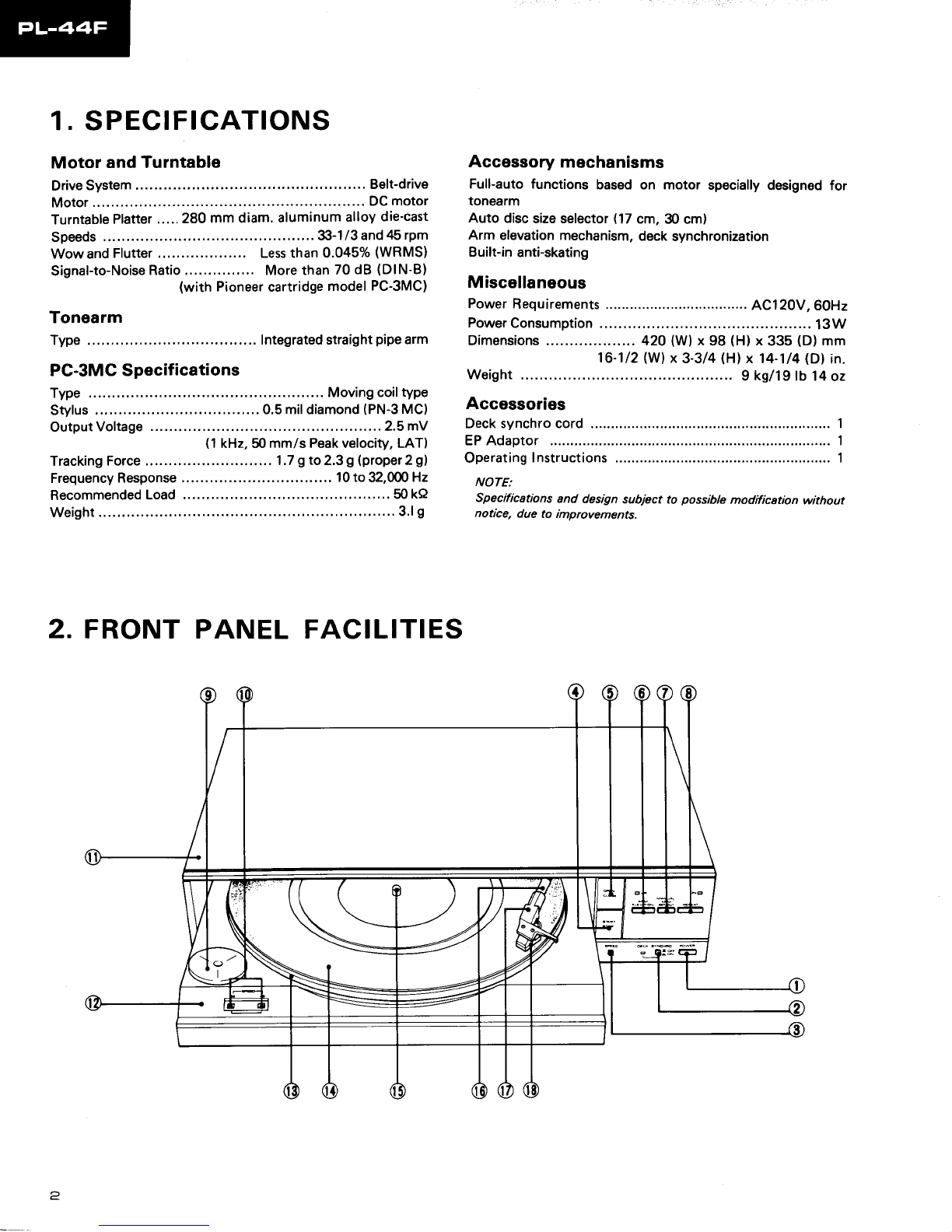
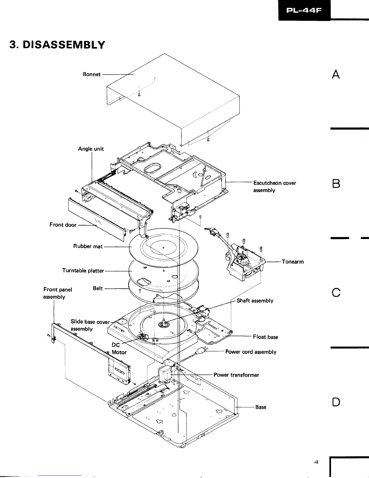
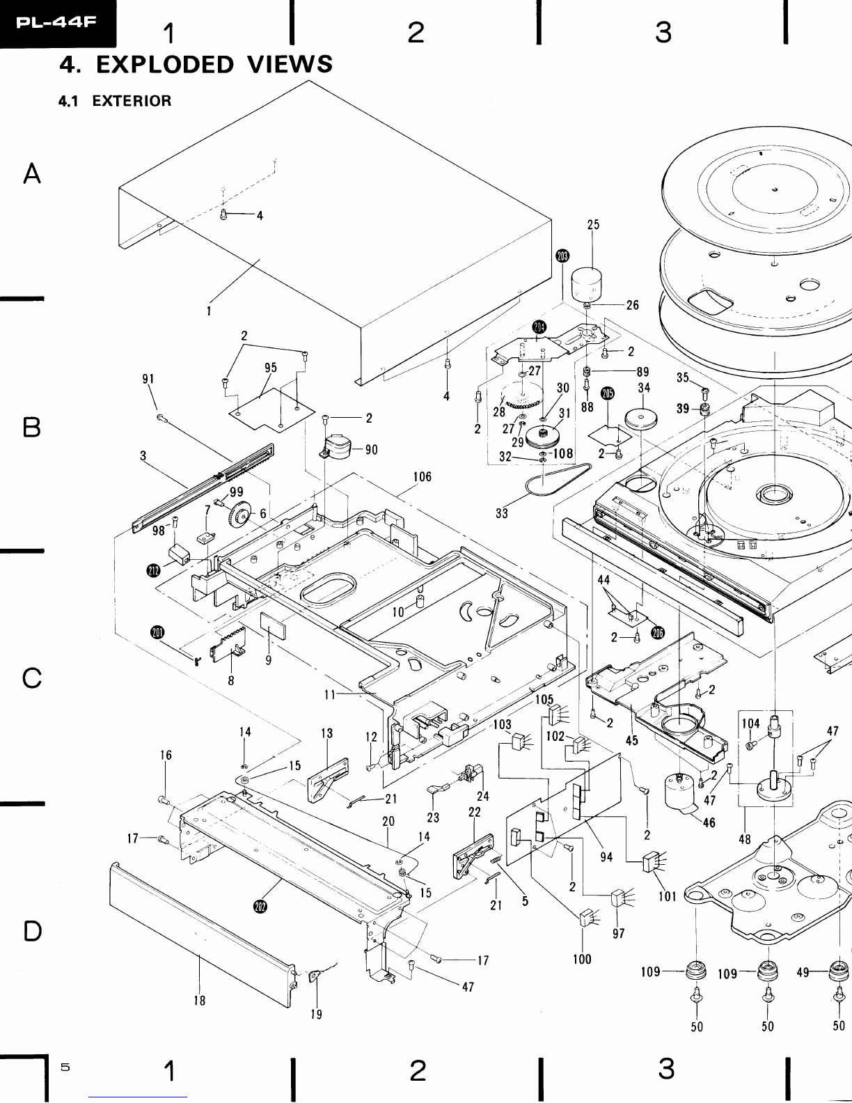
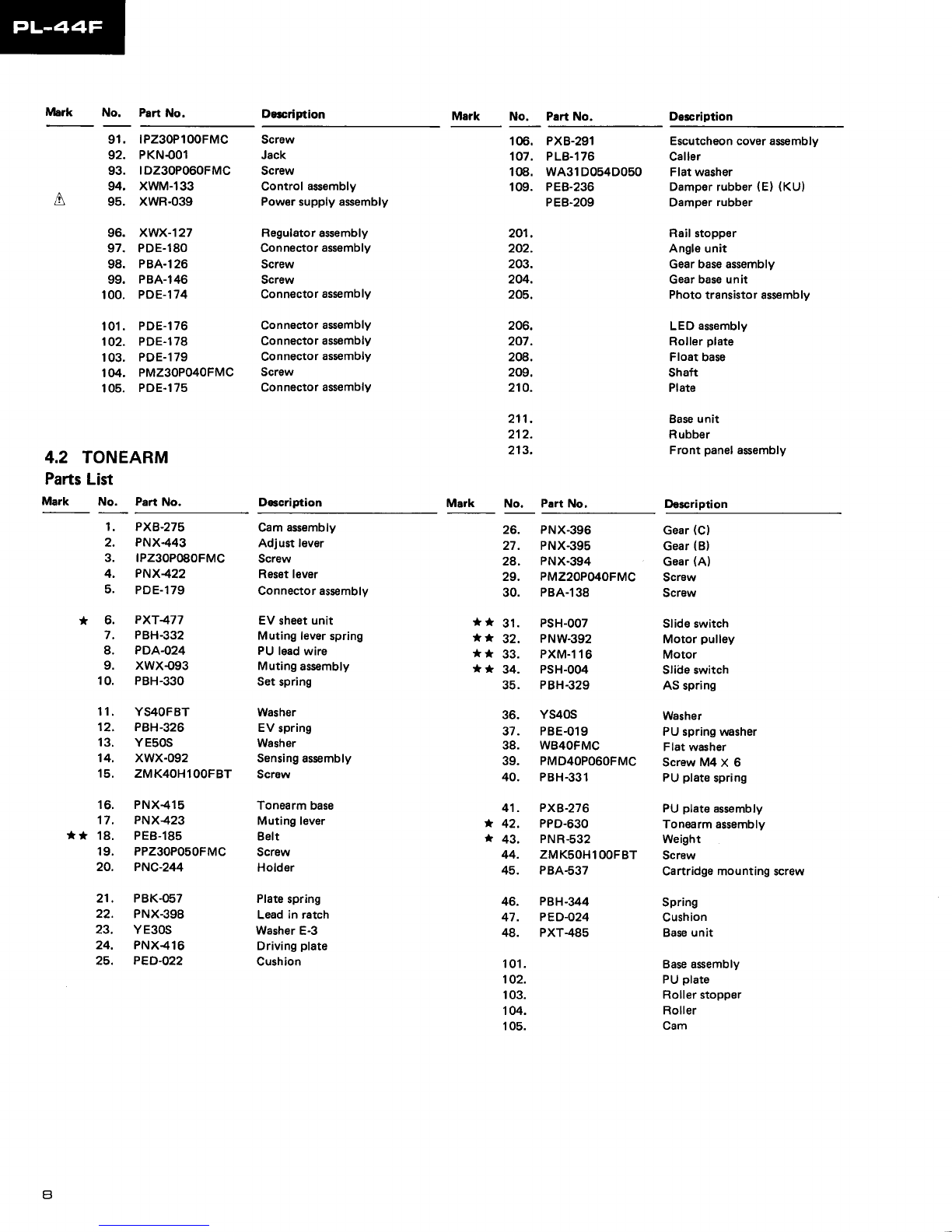
Pioneer PL-44F User manual

()rrloruEER'
ORDER
NO.
ARP-139-O
STEREO
TURNTABLE
PL.44F
MODEL
PL-44F
COMES
IN FOUR
VERSIONSDISTINGUTSHED
AS FOLLOWS:
This isthe servicemanualfor modelPL44F/KU. Forservicing
of the HE,HBandStypes,
please
refer
to the additional
ssrvicemanualon page
25.
For
thecircuit
& mechanismdescription,
please
referto thePL-88F
servicemanual
(ARP-143).
@ manuel
d'instructionserefdre
aumode
der6glage.enfrangais.
Este
manualdeserviciotratadelm6todo
deajusteescritoenespafrol.
a
a
a
PIC,NEEFI ELECTFICINIC CCIFIPG,FIATICIN a .r, Meeu.o 1-chome, MesuFo-ku. Tokyo 1sB, Japan
PIC,NEEFI ELECTFIC'NICB [UBAI lNC. '1925 E. Dorninguez Sc., Long Beach, tra fo.nra 9OBIO U.S.A.
PfONEEFf ELECTFICINIC IEUFIG,PEI N.\,. Keerbeng aan 1, 2740 eewe.en, Beig um
PfONEEFI ELECTFIEINICB AUATFIALIA PTY. rrE . 1781e4 Ecundany Foad, B.aeside, V ctona 319s, A,usr.atia
FFO AUG. 1982 Printed
in,apan
Tvpo Voltlge Romerka
KU 1
20Vonly U.S.A.
model
HE 22OVsnd240V {Switchable) Europe
model
HB 220Vand240V {Switchabl€} U.K.modol
l1OV,l2OV,22OV
and240V
(Switchable) Generalexport model
CONTENTS
1.SPECTFTCAT|ONS
........
2.
FRONTPANEL
FACILITIES
3. DISASSEMB
LY
4.EXPLODEDVIEWS.
.. .. ..
5.PACKING
6,ELECTRICAL
PARTSLIST
.
7.P.C.
BOARDS
CONNECTION
8.SCHEMATICDIAGRAM
..,
9.ADJUSTMENTS
REGLAGE
AJUSTE.
DIAGRAM
5
10
'll
13
15
18
20
22
ADDITIONALSERVICE
MANUAL
(for
HE,HB,Stypes)
1.SPECIFICAT|ONS...... ..... ... 25
2.CONTRASTOF MISCELLANEOUSPARTS
.., 26
3.
ELECTRICAL
PARTSLIST ,,,.,,. 27
4.SCHEMATICDIAGRAM .... ... .. . 29
5.P.C.BOARDASSEMBLY ..,...., 33

1. SPECIFICATIONS
Motor andTurntable
Drive
System Belt-drive
Motor......... DC
motor
Turntable
Platter
.....280
mmdiam.
aluminum
alloy
die-cast
Speeds 3-1/3 and
ztS
rPm
Wowand
Flutter........ LessthanO.O4SY>
(WRMS)
Signal-to-Noise
Ratio More
than
70dB (DlN-B)
(withPioneercartridge
model
PC-3MC)
Tonearm
Type.......... ........Integratedstraightpipearm
PC-3MCSpecifications
Type
.......... ....Movingcoil
type
Stylus
........ 0.5mildiamond
(PN-3
MC)
OutputVoltage............... 2.5mV
(1
kHz,50
mm/s Peakvelocity,LAT)
Tracking
Force,......... 1.7
gto2.3g
(proper2g)
Frequency
Response 101o32,000Hz
Recommended
Load ........50
kA
Weight .........3.lS
2. FRONTPANELFACILITIES
Accessorymechanisms
Full-autofunctions basedon motor speciallydesigned
for
tonearm
Auto disc
sizeselector
(17cm,30 cm)
Arm elevation
mechanism,
deck
synchronization
Built-in
anti-skating
Miscellaneous
Power
Requirements AC120V,60Hz
Power
Consumption .........
13W
Dimensions . 420 (W)
x 98 (H)
x 335(D)
mm
16-1/2
(W)
x 3-3/4
(Hl
x 14-1/4
(D)
in.
Weight 9 kg/tg lb14
oz
Accessories
Decksynchrocord............ ...........................1
EPAdaptor .........1
Operating
Instructions .............
1
NOTE:
Specifications
anddesign
subjecttopossible
modification
without
notice,duetoimprovements.

o poweR
switch
Pressthis switch to turn the power on and off.
Depressed
( -a I position:
Power
isswitched
ON.
Released( I )position:
Power
is
switched
OFF.
Whenthe POWER
switchissetto ON, thefollowing
swit-
ches
areset
automatically.
ARMELEVATIONswitch
* UP,
MANUAL
ARMSET/CUT
switch
* OFF,
REPEAT
switchr OFF
@ oecr sYNcHRoswitch/indicator
Thisswitch isusedwhenatapedeckhas
beenconnectedto
thisunit using
theaccessorycord.
Depressed
( r ) position:
Foroperations
whicharesynchronizedwith the tape
deck.
Released( .1 )position:
Foroperationswhich are
notsynchronizedwith the
tapedeck.
@ SPeeOselector
switch
Thisispressed
sothatthespeedindicatorlightsin line
with
the ratedspeedof the recordwhich is to be played.
"(s|)" lights:
For
playing
33-1/3
rpmrecords.
"(45)" tights:
For
playing
45 rpm records.
@ sranr/sToP switch
o Pressthis switch to start auto play.
r Pressthis switch to stop auto play.
@ operulclosEswitch
o Thisis pressed
to open
andclosethedoorandto bring
out andretracttheslidebase.
r lt isalso
pressed
to stopautoplay.
@ ARM ELEVATIONswitch/indicator(UPl
o Pressthisswitchto startmanual
play.
. Usetheswitchto suspend
record
play
temporarily.
. Usethe switchwhen changingthe tracks
(with manual
playl
duringactual
play.
"UP" indicatorIights:
Thetonearmrises
(the
stylusmoves
away
from the
record).
"UP" indicator
goes
off:
Thetonearm
descends
(the
stylusislowered
ontothe
record).
o rtleruuAL
ARM
SET/CUTswitch
r Pressthisswitchfor manual
play.
o Press
thisswitchto stopmanual
play.
@ nePgnT
switch/indicator
Pressthisswitch
sothattheindicatorlights
for repeat
play.
@ gPadaptor/EP
adaptorholder
Slide
the EPadaptoroverthe platter
shaft
whentherecord
youwant to play
does
not have
a "middle".
Keep
theadaptor
onthe
holderwhen
it isnotinuse.
NOTE:
Make surethat you use the EPadaptor which is supplied with this
unit. Using any other adaptor may invite contact with the
with the result that the stylusmay be damaged.
@ Speedindicators
{frt,45}
Theseindicate
theplatter
speed.
"(33)" lights:
Platteris
rotatingat33-1/3rpm.
"(45)" lights:
Platteris
rotatingat45rpm.
@ Bonnet
@ stidebase
@ Platter
@ nubber
mat
NOTE:
Always use the rubber mat which is supplied with this unit. lJsing
a different rubber mat will change the stylus height and may cause
malfunctions.
@ Plattershaft
@ Tonearm
@ Headshell
@ Cartridge
(PG-3MC)

3. DISASSEMBLY
Rubber
mat
Turntable
platter
Front
panel Belt
Escutcheon
cover
assembly B
- -
Shaft
assembly
D
A

3
2
EXPLODEDVIEWS
EXTERIOR
A
B
C
DI
roe-9
I
&
I
50
12
4
=gd"
-l5
o,-9
t

65
4
,47 A
63 9l
/ / eg
d/,/
62
73---{ l
tul
tllry
,
)"ll -\6: B
72
8-6
- - --J
l',1,Nir
\
C
75
[--*
I
&
I
50
D
,on-@o*$E- s2
t @_53
6
5
4
4l
+o\
A\
t*-d-'
)'b,l |
)'
'o | 19fl
./go \
-/ 8.3 \

PartsList
Mark No. PartNo.
NOTES:
o Parts without part number cannot besupplied,
o The I marh found on some component parts indicates the importance of the
cafety factor of the part. Therefore, when replacing, be sure to use
parts of identical
designation.
o For your Parts Stoch Control, the fast mouing iteme are indicated with the
marhs ** and *
** GENERALLY MOVES FASTER THAN *
This clusification shall be adiusted by each distributor becauseit depends on model
number, temperature, humiditY, etc.
Description Mark No, Part
No. Description
1.
2.
3.
4.
5.
6.
** 7.
8.
9.
10.
11.
12.
13.
14.
15.
16.
17.
18.
19.
20.
21.
22.
23.
24.
25.
PNA-l70
PP23OPOSOFMC
PNX437
PDZ3OPO6OFZK
PBH-342
PNX436
PSH-007
PNX435
PED.O23
PEB.2O7
PXB-291
PMA3OPOSOFMC
PNX-438
YE25S
PNX44O
PPZ26PO5OFZK
PDZ3OPOSOFMC
PNX.378
PYY.1
15
PBLOOl
PBK-058
PNX439
PNX.387
PSG-024
PXM.I17
PNX449
wA41D065D25
PNX43O
YE3OS
wA31
D054D025
PNX429
YE2OS
PE8-206
PNX442
PBA.I
12
PEB.205
PNR-174
PEB-183
PEB-172
PDZ3OPOSOFMC
PNX.45O
PXB.263
PNX424
GL-gPG12
PNY.O26
PNX.441
Bonnet
Screw
Driving
leverrack
Screw
Spring
Gear
(F)
Slide
switch
Slider
Rubbercushion
Rubber
Escutcheoncoverassembly
Screw
Doorholder
(L)
Washer
Pulley
Screw
Screw
Front
door
Door
holder
assembly
Wire
Spring
Door
holder
(R)
Pknob
Power
switch
Motor
Motor
pulley
Flatwasher
Gear
(E)
Washer
Flatwasher
Gear
(D)
Washer
Belt
45adaptor
Screw
Rubber
matassembly
Turntable
platter
Belt
Rubber
cushion
Screw
Wire
guide
Slidebasecoverassembly
Roller
LED
Cover
(KU Typel
Cover
(HE.HB,S
Typesl
61
.
62'
63.
64.
[, 6s.
66.
67.
68.
69.
** 70.
PEB.2O8
PBH.335
PBA.140
PNX.434
PNX-433
PNX432
PNX431
PNC-251
PNX.428
PNX.426
PNX-231
PNC-253
PDGO4O
PXB-294
PMZ3OPlSOFMC
PEC-048
PBA.138
PSHOO9
* * 46. PYY-I14
47. PDZ3oPo8oFMC
48. PXB274
49. PE8-209
50. PBA-141
Motorassembly
Screw
Shaft
assembly
Damperrubber
Screw
(B)
Damper
rubber
Spring
(A)
Screw
(A)
Lockleverroller
Locklever
Lockplate
Lowering
rack
Slide
rail
Sliderail
rack
Retainer
Steel40
Steel60
Gear
Railcover
Power
cordasembly
PUcord
assembly
Screw
Strainrelief
(Power
cord)
Screw
Slideswitch
Strain
relief
(PU
cord)
Stopper
(Rubber)
Screw
Power
transformer
(
120V)
Functionassembly
Screw
Screw
Rollerangle
assembly
Front
panel
(B)
Lens
(A)
DSknob
EVknob
Knob
spring
O/C
knob
unit
S/Sknobunit
Operation
panel
Panel
holder
Screw
Rubbercushion
Lamp
cover
51.
52.
53.
54.
55.
56.
57.
58.
59.
60.
**
**
** 26.
27.
24.
29.
30.
31.
32.
33.
34.
35.
**
36.
37.
** 38.
39.
40.
41
.
42.
43.
* 44.
45.
A
71. PECOs1
72. PECO73
73. PMA4OPO6OFMC
* 74. PTT-154
75. PNX-076
76. PDZ30P100FMC
77. PDZ30P060FMC
78. PXB-278
79. PNX-402
80. PNX-413
81. PNX-386
42. PNX410
83. .
PBH-328
84. PAD-105
85. PAD-I06
86. PNX404
47. PNX407
88. PBA-125
89. PEB-184
90. PNX-425

Mark No. Part No. Dorcription Mark No, Part
No. Description
,A
4.2 TONEARM
Parts
List
Mark No. Part No.
Screw
Jack
Screw
Control
assembly
Powersupplyassembly
Regulator
assembly
Connector
assembly
Screw
Screw
Connector
assembly
Connector
assembly
Connector
assembly
Connector
assembly
Screw
Connector
assembly
D6cription
106. PXB-291
107. PLB-l76
108. WA31D054D050
109. PEB-236
PEB.2O9
201.
202.
203.
204.
205,
206.
207.
2@.
209,
210.
211.
212.
213.
No. PartNo,
Escutcheoncoverasembly
Caller
Flatwasher
Damperrubber
(E)(KU)
Damper
rubber
Railstopper
Angle
unit
Gearbaseassembly
Gear
baseunit
Photo
transistorassembly
LED
assembly
Roller
plate
Floatbase
Shaft
Plate
Baseunit
Rubber
Frontpanel
assembly
Description
91. tPZ30P100FMC
92. PKNOo1
93. tDZ30P060FMC
94. XWM-133
95. XWR-039
96. XWX-127
97. PDE-l80
98. PBA-126
99. PBA-146
100. PDE-174
101. PDE-I76
102. PDE-178
103. PDE-179
104. PMZ30P040FMC
105. PDE-I75
Mark
1. PXB-275
2. PNX443
3. tPZ30P0B0FMC
4. PNX-422
5. PDE-179
* 6. PXT477
7. PBH-332
8. PDA-O24
9. XWXOg3
10. PBH-330
11. YS4OFBT
12. PBH-326
13. YE50S
14. XWX-092
15. ZMK4OHlOOFBT
16. PNX415
17. PNX423
** 18. PEB-185
19. PPZ30P050FMC
20. PNC-244
21. PBK-057
22. PNX-398
23, YE30S
24. PNX-416
25. PED-O22
Cam
assembly
Adjustlever
Screw
Resetlever
Connectorassembly
EV
sheet
unit
Mutinglever
spring
PU
leadwire
Muting
assembly
Set
spring
Washer
EV
spring
Washer
Sensingassembly
Screw
Tonearmbase
Mutinglever
Belt
Screw
Holder
Plate
spring
Lead
in ratch
Washer
E-3
Driving
plate
Cushion
PNX.396
PNX.395
PNX.394
PMZ2OPOIOFMC
PBA.138
PSH-OO7
PNW.392
PXM.116
PSH-004
PBH-329
YS4OS
PBE-019
WB4OFMC
PMD4OP06OFMC
PBH-331
PXB-276
PPD.630
PNR.532
ZMKSOHl
OOFBT
PBA-537
PBH.344
PEO-O24
PXT.485
Gear
(C)
Gear
(8)
Gear
(A)
Screw
Screw
Slideswitch
Motor
pulley
Motor
Slideswitch
ASspring
Washer
PUspringwasher
Flatwasher
ScrewM4X 6
PU
plate
spring
PU
plate
assembly
Tonearmassembly
Weight
Screw
Cartridgemountingscrew
Spring
Cushion
Baseunit
Baseassembly
PU
plate
Rollerstopper
Roller
Cam
26.
27.
28.
29.
30.
** 31.
** 32.
** 33.
** 34.
35.
36.
37.
38.
39.
40.
41,
* 42.
* 43.
44.
45.
46.
47.
48.
101.
102.
103.
104.
105.

fr'
fll tI
t4 l5
S-et !'
30
I
8
.L
3t_p
t9_g
,*4
g
32\

5. PACKING
PartsList
M.,k No. P.rt No, D.rc.iption
6. PNX45I Tonearmholder
7. PNX452 Spacer
8. PBA-'141 Screw
(Bl
9. |PZ40P250FMC Screw
10. PMZ4e160FMC Screw
1. PNX442
2. PRB-219
3. PHHO14
4. PHA-146
5. PHA-147
45 adaptor
Operating
instructions
Packingcas6
Protector
(F)
Protsctor
{R)
Screw
Tapedecksynchrocord
Spac€r
(A)
Notopaper
Notepaper
Not€paper
11. tPZ3oP120FMC
12. PDE-I57
13. PNX4?4
14. PRW-O96
15. PRW-098
16. PRW-I03
n-'-v
la=
-.-\-{'
<7

6. ELECTRICALPARTS LIST
NO?ES:
o When ordeing resistors, first convert resistance ualues into code form asshown in
the following examples.
Ex. 1 When there are 2 effectiue digits (any digit apart from O),such u 560 ohm
and 47h ohm (tolerance
is shown by J=ift, and K=10%).
560fj" 56 x 10t 561. .. . . RD%PS Eltr[n J
47kn 47x103 473..... RD%PSEAE],trj
J
0.5a 0R5 . . . .. . RN2H @IBE, K
Isl 010 .. . . .. Rs.lP nEJ,@K
Er. 2 lllhen there are 3 effective digits (such u in high precision metal film
resistots).
5.62h{r 562 x lot 5621 . . . . RN%SR 6@AA F
c The f mark found on some cotnponent parts indicates the importance of the
safety factor of the part. Therefore, when replacing, be sure to use parts of
identical designation.
o For your Parts Stoch Control, the fast moving items are indicated with the
marks ** and *
** GENERALLY MOVES FASTER THAN *
This clasification shall be adjwted by each distributor because it depends on
model number, temperature, humidity, etc.
Miscellaneous
Parts
P.C.BOARD ASSEMBLY
Mark Part No. Symbol & Description
CONTROL
ASSEMBLY
(XWM-llB)
CAPACITORS
Mark Part
No, Symbol& Description
XWM-133 Controlassembly
A XWR-039 Power
supply
assembly
XWX-127 Regulator
assembly
PWX-076 Functionasembly
LED
assembly
LEDassemblyA
XWX-092 Sensing
assembly
XWX-093 Mutingassembly
*LED assemblyiscomposedof LEDassemblyA, Phototransistor Mark PartNo'
cEA 100M
16L C6,C't1
,C14
cEA1RoM50L C8.Cl0,C15
CKDYF104250 C13
cKDYF 1032
50 C7,C16,C17
cszA 6R8K16 c12
RESISTORS
PhotoTransistorassembly NOTE:When ordering resistors, conuert the resistanceualue
into code form, and then rewrite the part no. as before.
Symbol& Description
assembly.
SWITCH,SEMICONDUCTOR
Mark PartNo.
* PCP-075
* PCP-069
* PCP-067
VR'l Semi-f
ixed
VR2 Semi-fixed
VR3 Semi-fixed
Symbol& Description RS1PF151J R1O
RS2HSFB33OJL R15
RGSD8X472J R23
RN%PRl5O3F R7
RD',/4PMntrtrJ B3-R6, R9, Rl1-R14, R16-R22,
R30,
R31,
R33-R43
RNz+PR
1503F R7
RN74PR
4R7F 832
a * * PSG-024
* * PSH-oog
* * PSH-OO7
* * PSH-004
MOTORS,
OTHERS
Mark Part No.
Power switch
Slideswitch
Slide
switch
Slide switch
Symbol& Description
* GL-9PG12 LED
* * PYY-I14 Motorassembly
(Phono)
* * PXM-116 Motor
(Tonearm)
* * PXM-117 Motor
(Slide
base)
A * PTT-154 Power
transformer
A PDG-040 Power
cordassembly

SEMICONDUCTORS
Mark Part No. Symbol& Dercription REGULATORASSEMBLY
(XWX-127)
Mark Part No. Symbol & D$ctiption
** 846109
** 8A6208
** PD2003
** M884001B
*t 2SC1815
(2SC2458)
(2SC945)
** 2SC945-P
** 2SC1959
r* 2sc1815-Y
82-061
RD3.6EB
152473
{1S1555)
1S1885
152473
vD1222
rc3
tel
tc5
rc6
01,04,05.07,08,ol 0,011
D2
D3
D4,D5
D6
07
D12,Dl3
Symbol& Description
t r PsG-038
i r PsG-039
RD%PM
NDtrJ
s
1-s5
s6,s7
R25-R27
Symbol
& DGcription
02
o3
09
* NJM7815A
PDE.177 lc1 Connector
(3P)
OPERATION
ASSEMBLY
(PWX.O76}
SWITCHES,
RESISTORS
NOTE:When ordertng resisfors,conuert the resistance
ualue
into codeform, and then rewrite thepart no. as
before.
Mark PartNo. Symbol& Description
t
*
*
*
*
*
SEMI
CONDUCTORS,OTHERS
Mark PartNo.
OTHER
Mark Pan No,
t GL.gPR2
* GL.9NG12
PNX454
PNX-446
PDB.181
LED ASSEMBLY
Mark PartNo.
D9,Dl 1
Dl0 LED
holder
(C)
LEDholder
{B}
Connectorassembly
(14P)
Symbol& Dercription
PKN.OOl
POWER
SUPPLYASSEMBLY
(XWR-039}
CAPACITORS
Mark Part No. Symbol & Description
PDE.182
LED ASSEMBLY
A
Mark PartNo.
Connector
assen{oly
Symbol& Deccription
PCL-O40
CEA471M35L
CEA1
ROM
sOL
CEA
R47M
sOL
RESISTORS
Mark PartNo.
c1
c2
c3
c4,c5
Symbol& Description
-
RD1/1PM271J
PHOTO
TRANSISTOR
Mark Part No.
R28,R29
ASSEMBLY
Symbol& Description
RSlHSFB22OJL
RS2PF151
J
SEMICONDUCTORS
Mark PartNo.
R1
R2
Symbol& Description
** PH101 06
*LED assemblyis composedof LED assembly
A, Photo transistor
assembly.
SENSINGASSEMBLY
(XWX.Ogz}
Mark PartNo. Symbol& Description
** NJM78MOsA
r Pcx-010
(wL{2)
LAMP,
OTHER
Mark Part
No. Symbol& Description
tc2
D1
* * PEL-051
PNY{ff) L1 Lamp
Lamp
holder
* pcx€3t
* * PEL-0/IB
PNX-302
PDE.176
MUTINGASSEMBLY
Mark PartNo.
Cds
Lamp
Lamp
holder
Connectorassembly
(xwx-093)
Symbol & Deccription
* * PSG-043
PDF.145 513 Push
switch
GNDwire

E17. P.C. BOARDSCONNECTION
S IZI:POWER
st4
3
2I
DIAGRAM
APOWER SUPPLY Ass'y
(xwR-o3e)
AC t20V
6OHz
CONTROL Ass'y
(xwM- t33)
tc8 0ro Q9 Qil
REGULATOR
Ass'y (XWX- |27) PHOTO
TRANSISTOR Ass'y
LOADING
MOTOR
L---------J
END
(xw
I32
LED Ass'y

*'f 6
5
4
MUTING Ass'y
58:UP 59:RESET
tc5
A
B
Ct
FUNCTION Ass'y
ARM MOTOR
NO
------o
st2:
Ncl
fl
(l
ll
5
END SENSOR Ass'y
(xwx-o92)

3
2
1
8. SCHEMATICDIAGRAM
PHOTO
TRANSISTOR
Ass'y
(2/21
r{c No r{c NO
sil : PsH-oo9
Sl2:
PSH-OO? stl
cLosE0
3-3
si2
OPEN
IC6, Q9-ll
STO
P
33r
R33 09
r5l -
l--- s14:
PowER
- st4 PSG-O24
Y0l
R35r50k
I
I
-
B
LOAOING
MOTOR
PXM-il7
L_________i
t-
END
SENSER
4."'y L
xwx-092
iiF-r
2{r, "rr-
rse
f--------1
ACPOWER
CORD
P0G-040
A
ACr20V
60Ht
I
DEC
K
SYNCHRO
L___j
il(
"f
t
RES
PSH
ON
ON
ON
ON
ON
D__ _-J
ct
I
pcL-o4o Dl PCX-OtOorWL-O2
Ll: PEL-05t IC2 NJM78MOSA
EV 55nA
FORDISC
DETECTOR
POWER
SUPPLYAss'y XwR-O39 A
SWITCHES
SI
s3
s4
5C
OPEN CLOSE
START STOP
ARM ELEVATION
REPEAT
MANUALARM sET
132
3''1" LEAO LEAD
z ,,H,, rN ,,L,. our
MOTORDRIVER
rc4
I
t{c
2
INPUTA
3
INPUT
B
4
NC
GiID
7
OUTPUT A
I
OUTPUT
B
9
NC
I
GNO
2
Vu I
4
F
IN
6
RIN
7
8
vcc 2
9
Vzz
to
V@r 2
IC3
s"L" LoAo{rG 1i" LoADt}rG
OUT IN
Q7,8
DECKSYNCHRO
Ril too Rrz
3.91
QI,2 END DETECTOR
I ,.,t1
;NJM78r5a
REGULATOR
Ass'v
7.2 xwx-127
REGULATOR ! D

5
4I
I
t^l
OI NOTE:
:#":Hji{nii
FUNCTION
Ass'y
i
I
ICoNTROL
Ass'y XwM
-
133 A
t2
vRI
vR 2
vR 3
PCP-O75
PCP-O69
PCP
-
067
D2 82-06i
D
3 RD3.6EB
D4,5,7 152473
a
vR3
2t- B
II
PU
coR0
D6 tSr885
Dt?,i3 VDt222 IC
3 BA6rO9
IC4 8A6208
IC 5 PO2003
IC 6 M884001B
Q
r,4,5,7,
I,tO,r1
2SCt8r5
Q2 25C945
Q3 zSCl959
Q9 2SCr815
R39
It
t5
/50 !-
LOAOING
IN
s6 : oEcK
SYNCHRO
57 : SPEEo
|'1"r.u
..o*
l t3ro",
.ro"
I ti"" .rruo.o*
l'l."ro,
I'lo"ro.-
o.,
,r,
D9,
t1
GL-
9PR2
Dro
GL.9NG12
vR
2 : SPEEo AOJ
(33rpm
)
vR3: SPEE0 AoJ(45rpo)
PXM-il6
ARM
MOTOR
ilo
s8
UP
PS
H
-OO4
I
I
L-
pse'occ
1-
L"-t"b:" _j PHIOl R
L-t't-t]rr-:i
sr-5 PsG-038
s6,7 PSG-O39
1.
RESISTORS:
lndicated
in a,%W,'/aW,t5%
toleranceun16 otheMi$
M :
M',, (F)
:
: l%,
(G)
:
x2%,
lKl :
1
10%
(Ml; t20%t,
2.CAPACITORS:
Indicatedincapacity
(!F)/voltage
{V) unless
otheMis n
Indication
without voltage
is 50V exceptelctrolytic
3.
VOLTAGE
I rDCvoltage
(V)atnoinputsignal
4.OTHERS:
@ :
Adiusting
point.
The I markfound
on somecomponent
pans
indica
portance
of the
$tety factor
oI the
part.
Therefore,
whel
besre touse
pafts
of identicaldesignation.
X marked
capacitors
andresistoF
have
parts
numbe6,
Thisisthebasicshematicdiagram,but theactualcircui
dueto improvementsin
design.
270
LEDAss'y PHOTO
S6 : OECK SYNCHRO ON - OFF
s 7 : SPEED 33/3 rpm
- 45 rpm
58: UP ON-OFF
59 ; RESET ON
- OFF
TRANSISTOR
Ass'y
(1/21
SII : CLOSED ON - OFF
SI2 : OPEN ON
- OFF
Si3 : MUTING ON
- oFF
st4 : PowER(STAND-BY)
Onr-Orr
Theunderlined
indicatestheswitch
position.
MUTINGAss'y L clatnloeE m
l
CLOSE ON - OFF
T STOP ON - OFF
ELEVATION ON - OFF
AT ON - OFF
IAL ARM SET ON - OFF
46
5
-lI
| ,. s CoNTROL
IOPENSW
cLosED sw
UP
SW
4REST
SW
5ARM CW
6ARM CCW
7
LOAo CW
ILOAo CCW
9
SYNCHRO
to
PHONO
12 EV UP
LED
tf,
MANUAL
t4
GNO
2A
xrt
25
O/C KEY
24
S/S KEY
23
EV KEY
22
REP KEY
2l
MAI{ KEY
20
SPEEO
t9
ENO
IN
t8
otsK tN
t7
INT
_ t6
RST
t5
REPLEO
t-12 | | llsT
i'ii"
I-

T
I
I
t7l
NOTE:
The indicatedsemiconductors
are repre*ntative ones
only. Otheralternative
semiconductots
maybe
used
and
arelisted
in the
partslist.
I
8I
External
and
lCs
2SC945
2SCl815
2SC1959
Appearance
of Transistors
l0NAss'y
NJUfrSll,l05A
NJruTrSlSA
2*24F4
8A6109
8A6208
PD2003
PHlOl
R
M8840018
OPEN
CLOSE
l tSro*t
,ro"
f tiru ..ruo'o*
l'lr".o,
I tionro.
o"u
,.,
D9,r1
GL-
9PR2
Dro
GL-9NG12
OFF s6 : oEcx
SYNCHRO
57 : SPEED
E
-
-5 PSG
i,7 PS
Go38
o39 I
4W,15% lolerance unle$ otheruise noted k: ko,
j) : r2%, {K} : i l0% (M); t20% tolerance
(!F)/voltage (V) unless
otherwisenoted p I pF
/oltage is 50V except elstrolytic capacitor.
i
l at no input signal
i on some component pans indicates the im-
/ tactor of the part. Theretore,
when replacing,
identical
designation.
sand resastoF
have parts numbers.
natic
daagram,
but the actual circuit may vary
n
desrqn.
€
n
/\
v
tl
ll D
I
8
7
#;.j,""
A
,rO"*.S
*']ffi"'""
ililil B
'il!il"
-

9.ADJUSTMENTS
9.1STYLUS LOWERING POSITION ADJUST.
MENT
1. hess the OPEN/CLOSE key, pull the slidebase
out forwards, place a 30cm record on the tun-
table platter, and set the correct Revolution by
the speedselector.
2. Pressthe START key to start play. Check the
direction and degree of stylus displacement at
this time.
(Estimate the approximate distance in mm that
the stylus lands from the lead-in gtoove).
3. Depending on the direction and degree of dis-
placement, adjust the adjustment screw indicat-
edin Fig. 9.1with a small screwdriver.
* TUm the screwclockwise (asseen
fromabove)
if the stylus lowers outside the lead-in gfoove.
* T\rrn the screw counter clockwise (as seen
from above) if the stylus lowers inside the
lead-in gloove.
* One half-tum of the screw corresponds to a
shift of about 9mm in the lowering position.
4. When using the PLS-2001Stest record, adjust
the screw to obtain a count in the 305 to 317
range for lowering onto a 30cm record. And if
the GGF-021 test record is used, adjust to a
count between 6 and 30 for a 30cm record.
Nofes.'
* Remornl of the bonnet simplifbs adjustment oper-
ations.
In thb case,djuetmentE canbe
performed from
the top of the eecutcleon couer.
* Do not hcline the turntable ouer too far, not apply
excesiue prcesuve
to the adjustment acrewduring the
ad,jtstment operatio
n.
9.2 END DETECTOR ADJUSTMENT
1. Remove the bonnet, svyitchthe power on, press
the OPEN/CLOSE key, and pull the slide base
out forwards.
2. Press the MANUAL key to put the turntable
into manud play mode, and then switch the
power off.
3. Disconnect the CN2 and CN4 connectors on the
common circuit board, and connect a DC volt-
meter to pin l ard pin 3 (GND) of TP1.
4. Switch the power back on, move the stylus to a
position 47.5mm from the center spindle, and
readthe voltage.
5. Then move the stylus to a position 57.5mm
away from the center spindle and read the
meter again. The difference between the two
voltage readings should be 5.6V t 0.2V. Adjust
VRl to obtain this difference.
Adjustmenthole
(in
thebase
plate)
Fig.
9.1 Stylus
LoweringPosition
Adjustment
Fig.
9.3 End
Detector
Adjustment2
Screwdriver
Centerspindle
Fig.9.2 End
detectorAdjustment
1
fl
-l- g
flrt"ifl
.Ufl
1
1A
Fig.9.4 Adiustment
Position

6. The voltage difference is decreasedby ttuning
VR1 clockwise, and increasedbyturning counter
clockwise(see
Fig. 9.4).
Note:
Shade the sensor section from erternal light during this
adjustment.
9.3 PHONO MOTOR SPEED ADJUSTMENT
1. Remove the bonnet and switch the power on.
Place a stroboscope on the turntable platter,
and press the MANUAL key to put the ttun-
table into manual play mode.
2. Switch the speed selector to 33-1/3rpm, and
adjust VR2 to obtain the "stationaxy" strobo
effect.
3. Then switch the speed selector to 45rpm, and
adjwt VR3 to again obtain the ,,stationary,'
strobo effect.
4. Turntable speed is increased by turning the
adjustment controls (VR2 and VR3) clockwise,
and decreased
by turning counter clockwise.
9.4 STYLUS HEIGHT ADJUSTMENT
1. Remove the bonnet, switch the power on, press
the OPEN/CLOSE key, and pull the slidebase
out forwards.
2.Place a record on the turntable platter, and press
the MANUAL key to movethe tonearm forwards.
3. While holding the tonearm in the left hand,
adjust the adjustment screw with a wrench
(1.5mm) passd through the adjustment hole as
shown in Fig. 9.6.
4. Adjust the stylus to a height 5 to gmm above
the reeord.
Fig.
9.5 Phono
Motor
SpeedAdjustment
Wrench
(1.Smml
Tonearm
Height
adjustrnent
screw
fl
rill U
flrufl
Ufl
vnzffg
ypj VRl
B
-
b
Fig.9.6 Stylus
Height
Adjustment
_i 19

9.REGLAGE
9.1 REGLAGEDE L'EMPLACEMENT
D'ABAISSEMENT
DE L'AIGUILLE.
1.Presserla ci6 OPEN/COLSE, tirer la basecoulis-
santeversI'avant, mettre un disque de 30cm. sur
le plateau et positionner le s6lecteur de vitesse
sur le nombre Rdvolution correct.
2. Presser la ci6 START pour faire marcher Ie
tourne-disques. V6rifier la direction et le degr6
de d6placement de I'aiguille d ce moment.
(Estimer la distanceen mm. del'6loignement de
l'aiguille du premier sillon.)
3. Selon la direction et le degr6 de d6placement,
r6gler la vis de r6glage avec un petit tournevis
commeil estindiqu6 Fig. 9.1.
x Toumer la vis vers la droite (en regardant
du dessus) si I'aiguille s'abaissei I'int6rieur
du premiersillon.
* Tourner la vis vers la gauche (en regardant
du dessus)
si l'aiguille s'abaissei I'ext6rieur
du premier sillon.
* Un demi tour de la vis correspond i un d6-
placement de la position d'abaissement de
9mm environ.
4. Lorsque le disque d'essai
PLS-2001Sest utilis6,
r6gler la vis pour obtenir une lecture entre 305
et 3I7 pour I'abaissement
surundisque
de30cm.
Pour le disque d'essai GGF-021, r6gler pour
obtenir une lecture entre 3 et 30 pour un disque
de30cm.
Remarques:
* Enleuer le capot facilite l'opdration de riglage. Dans
ce coa,Ie riglage s'opire par le haut, sous le couuercle
d blason.
* Ne pas incliner Ie tourne-disques exag6riment, ne pas
appuyer trop fortement sur la uis de rdglage pendant
lbpiration.
9.2 REGLAGE
DU DETECTEURDE FIN
1. Enlever le capot, mettre I'appareil soustension,
presser la cl6 OPEN/CLOSE et tirer la base
coulissanteversI'avant.
2. Presser
la cl6 MANUAL pour mettre I'appareil
en mode manuel, puis couper I'alimentation.
3. D6brancher les prises CN2 et CN4 de la plaque
de circuits commune et brancher un voltmdtre
DC surlesergots1 et 3 (GND) de TP1.
4. Remettre sous tension et amener I'aiguille i
une position 47,5mm du pignon central. Lire
levoltage.
Fig.
9-1 R6glage
d'abaissement
de
position
deI'aiguille
FiS.9-2 R6glage1dud6tecteur
def
in
Fig.9-3 R6glage2dud6tecteur
de
fin
Tournevis
Pignoncentral
e
o
R57,5 R47,5
20
Fig.9-4 R6glage
de
position
Other manuals for PL-44F
1
Table of contents
Other Pioneer Turntable manuals

Pioneer
Pioneer PL-12D User manual

Pioneer
Pioneer PL-200 User manual

Pioneer
Pioneer PL-707 User manual

Pioneer
Pioneer QuartzPLL PL-540 User manual

Pioneer
Pioneer PZ-115D User manual

Pioneer
Pioneer PL-7 User manual

Pioneer
Pioneer PL-990 User manual

Pioneer
Pioneer PL-51 User manual

Pioneer
Pioneer PL-L70 User manual

Pioneer
Pioneer PL-560 User manual

Pioneer
Pioneer PL-225 User manual

Pioneer
Pioneer PL-41 User manual

Pioneer
Pioneer PL-530 User manual

Pioneer
Pioneer PL-71 User manual

Pioneer
Pioneer PL-530 User manual

Pioneer
Pioneer DC-Z93 User manual

Pioneer
Pioneer PL-J2500 User manual

Pioneer
Pioneer PL-516 KUT User manual

Pioneer
Pioneer PL-Z93 User manual

Pioneer
Pioneer PL-630 User manual