manuals.online logo
Brands
  1. Home
  2. •
  3. Brands
  4. •
  5. Pioneer
  6. •
  7. Turntable
  8. •
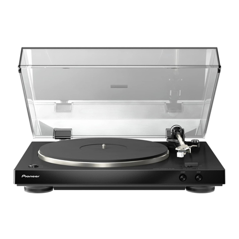
  9. Pioneer PL-110 User manual

Pioneer PL-110 User manual

Deze download wordt u gratis aangeboden door Pick-upnaalden.nl
Web : www.pickupnaalden.com
Email : [email protected]
Facebook : www.facebook.com/pickupnaalden
Twitter : twitter.com/Pickupnaalden
Google+ : https://plus.google.com/+FCaris_pickupnaalden
C)rlloNeeR'
\
{--
STEREO
TURNTABLE
PL-ll o
o Thisservice
manual
is
applicable
to theZE
type.
. Ce
manueld'instruction
serefdre
aumodede
r6glage,
enfrangais.
. Este
manual
de
servicio
tratadelm6todode
ajuste
escrito
enespafiol.
ORDER
NO.
ARP
-217
-O
7. P.C.
BOARD
CONNECTIONDIAGRAM 9
8. SCHEMATICDIAGRAM 10
9. ADJUSTMENTS
. 11
REGLAGE 12
AJUSTE 13
CONTENTS
SPECIFICATIONS
FRONT
PANEL
FACILITIES
.
DISASSEMBLY
EXPLODED
VIEWS
ELECTRICAL
PARTS
LIST.
1.
2.
3.
4.
5.
6. PACKING
2
2
3
5
I
8
PICINEEFI ELECTFICINIC CCIF|PCIFIATICIN 4-1 , Mesuno 1-Chome, Mesuno-ku, Tokyo 1ss, Japan
PIGINEEFI ELECTFICINICCi IUSAI lNC. '1925 E. Dorninguez St., Long Beach, Califonnia gO81O U.S.A.
PfONEEFI ELEcrFlctNtc [EUFloPEl N,v. t<eerbengtaan 1, p74o Bevenen, E]etgium
PIONEEFI ELECTFICINTC€! AUEITFIALIA PTY, LTEI. 17A-1A4 Boundany Fload, Bnaeside, Victotria 3195, Ausrnatia
FZ @ AUG.
1982 Printed
in J
aPan
1. SPECIFICATIONS
Motor andTurntable
Drive
System Belt-drive
Motor......... DCmotor
Turntable
Platter
.....
280mm
diam.
aluminum
alloydiecast
Speeds 3-1/3 and
45rpm
WowandFlutter
.
.
...... Lessthan
0.057o
(WRMS)
Signal-to-Noise-Ratio More
than68
dB
(DlN-B)
(with
Pioneercartridge
modelPC-K65)
Tonearm
Type
.......... Static-balancetype,
Straight
pipe
arm
Effective
ArmLength .... 190
mm
Overhang 9.3mm
Subfunctions
Auto-return
mechanism,
Free
stop
hinges
Miscellaneous
Power
Requirements ..D.C.
20V
Power
Consumption
.......... .................2.4W
Dimensions 422
(Wl
x 108
(H)
x 345
(D)
mm
16-3/8
lWl
x4-1/4
(H)
x 13-5/8
(D)
in.
Weight 3.2kg/7tb
1oz
PC-K65
Specifications
Type
......... Moving
Magnet
type
Stylus
......... 0.5mitdiamond
(pN-K6S)
Output
Voltage 3.5mV
(1
kHz,
50
mm/sPeakvelocity,
LAT)
Tracking
Force
.......... 2.1
g
to2.9
g(proper
2.5
g)
Frequency
Response 20- 2O,OOOHz
Recommended
Load ..... 47kO
Weight ........
3.4
g
Accessories
EPAdapter ........1
Instructions
note............. .......
1
NOTE:
Specifications and design subject to possible modification without
notice, due to improvements.
O PLATTER
@ PLATTEBMOUNTINGSHAFT
O RUBBERMAT
(D EPADAPTER
This is used when playing recordswithout a "middle."
(l cABrNEr
ti?ousr covER
2. FRONT
PANELFACILITIES
O speeo
swrrcH
Set this switch in accordancewith the speed of the record
which is to be played.
Depr6 "3" for playing3-1/3 rpm records.
Depres "45" lor playing45 rpm records.
@
cur swrrcH
Depressthisswitchto stopplay.
@ CARTRIDGE
(Pc.K65)
@ HEADSHELL
O ToNEARM
@ ARM REST
This serves to hold and clamp the tonearm. When moving
the tonearm, release the clamp.
e
3. DISASSEMBLY
Rubber
mat
assembly
Tonearm
assembly
PU
plate
(B)
assembly
@
A
n
14
I
3.1REMOVAL AND INSTALLATION OF
DETECTOR LEVER UNIT
1. Hold the detector lever unit with yourrighthand
as shown in Flg. 3-1, open the PU plate (A) and
PU plate (B) of the PU plate (B) assembly with
your left hand, and careftdly pull out the
detector lever unit upward.
2. Install the detector lever unit in reverse
sequence
of the removal. lt this case,however, note that
the detector lever unit will be bent when the pin
portion (A) is in contact with the detector lever
unit and the detector lever unit is pushed hard.
3.2REMOVAL AND INSTALLATION OF PU
PLATE (B} ASSEMBLY
1. Remove the base
plate and remove the PU board
plate.
2. Insert a slightly Iong screwdriver into the turn-
table through the opening on the back of
the turntable as shown in Fig. 3-3, and remove
the screwused
to fix the PU plate (B) assembly.
3. Install the PU plate (B) assembly in reverse
sequenceof the removal. In this case,however,
install the PU plate (B) assembly
sothatthe mark
on the panel is on tJre line extended from the
side
panel
of thePU plate
(B) (Fig.3-a).
PU
plate(B)-
plate(A)
Screwdriver
etector
leverunit
Fig.
3-1 lever
unit
(
Fi9.
33 RemovePU
plate
(B)
Fig.
3-4 AttachPU
plate(B)
Tonearm
assembly
PU
plate
(B)
wq/
-v/
Removedetector
PU
board PU
plate
(B)
PU
plate(B)
Panel
Green
Fig.
3-2 Attach detector
lever
unit
Fig.
3-5 Disconnect
thetonearm
lead
wires
3
2
I
VIEWS
4. EXPLODED
Exterior
9
6
A3
3
37
-8
U
t2@
ca
tg^f rK---]
-'1
$,J'l
i
h'i
ofr
B
r9
tu4
C
0 "A
i-g
lr9
26
't4
$
D
3
2
1
['--f
lR6 l
2,ff#
7---^@''
iilft"--*;"
8iffil/,
ll
f"
*---1"
\2
6
5
4
A
B
C
D
*l 6
4
Parts
List
Mark No. Part No.
NO?8S:
o Partswithout part numbercannot besupplied.
c The I marh found on some component parts indicatesthe importance of the
safetyfactor of thepart. Therefore,whenreplacing,
beeurcto uee
parts
of identical
designation.
o For your Parts Stock Control, the fast mouing items are indicated with the
marks** and,*
.
** GENEEALLY MOVES FASTERTHAN *
This clasification shallbeadjueted
by eachdistributor becauseit dependeon model
number,temperaturc,humidity, etc.
Description Mark No. Part No. Description
1. PXB-177
2. PDZ30P080FMC
3.
4.
5. PBA-I26
6. YE40S
7. PYY-100
8. PDZ30P050FMC
9. PP230P080FMC
10. PNX-035
11. PBH-225
12. PNX-465
13. PNX-031
14. tPZ30P100FMc
15. XWR-038
16. PBA-112
't7. PEB-172
18. PNY-O25
19. PMS-019
20. PYY-1
13
21
. PAC-I
18
22. PBH-340
23. PX8-283
24.
25. PSF-020
26. YE70S
27. PBK-059
24. PX8-285
29, YS4OFBT
30. wc40FMc
31. PNC-227
32. PNX-467
33. PNX-464
34. PMD4OPOSOFMC
35. PBH-308
36. PBH-224
37. PBA-I45
38. PMZ26P100FMC
39. PNX-304
40. PNC-220
Shaft assembly
Screw
Screw
E-type washer
Cam assembly
Screw
Screw
Lock plate
Lock plate
spring
Switch lever
Switch locker
Screw
Power supply assembly
Screw
Rubberbush
Panel
Cover
Motor assembly
Pushbutton
Spring
Cut poleassembly
Micro switch
E-type washer
R springwasher
PU plate (B) assembly
E-type washer
Flat washer
PU springwasher
PU plate (A)
PU
plate
(B)
Screw
PU plate
spring
Spring
Screw
Screw
EV cam
Start plate
41. PXT496
42. PXB-192
43. XWS-020
44. PNX466
t 45. PXB-284
Detector leverunit
Tonearm restassembly
Switch assembly
Cover
Tonearm assembly
EV assembly
Screw
EV spring
PU cord
Hingeassembly
Dust cover
Rubber mat assembly
Turntable platter
Belt
Damper
cushion
Screw
Protector
Shaft unit
Shaft
Sub-panelunit
Driving
plate
assembly
EV shaft
holder
PU board plate
lndex cam
Base
plate
GND leadunit
**
46.
47.
48,
49.
* 50.
51
.
52.
53.
54.
55.
56.
101.
102.
103.
1(x.
1
05.
106.
107.
1
08.
109.
110.
PXB-296
ZMK4OMOSOFZK
PBH.237
POE-212
PXB-155
PNV-034
PEA.O61
PNR-177
PEB-224
PEB.21O
PBA-143
L\
A
*t
**
5. PACKING
Parts
List
Mark No. PartNo. Description No. Part No. Description
6.
7.
8.
1.
2.
3.
4.
5.
N93€O3
PRHOOl
PE4.061
PHA-144
PHA-145
45 adaptor
Instructions
note
Rubbermat
assembly
Protector
(
L)
Protector
(R
)
PHH.026
PNX.294
PBA.144
Packing
case
Turntable
platterprotector
Screw
MiscellaneousParts
Mark PartNo.
6. ELECTRICALPARTS LIST
NOTES:
c Parts
withoutpart numbelcannotbe
supplied.
c The A marh found, on some component partc ind,icates
the importance of the
safetyfactor of thepart. Therefore,whenreplacing,
besureto uee
parts
of identical
d.esignation,
c For your Parts Stoch Control, the fast moving items are indicated with the
marhs** and,*.
** CENEEALLY MOVES FASTENTHAN *
This classificationehallbeadjustedby eachdistributor becauseit dependson model
number,
temperature,humid,ity,etc.
S,vitchAssembly(XWS-020)
Symbol & D$cription Mark PartNo. Symbol& De*ription
A XWR.O38
XWS-O2O
** PYY-I
13
* * PSF-020
PowerSupply
Assembly
Mark PartNo,
Power supply assembly
Switch assembly
Motor assembly
Micro switch
(xwR-038)
Symbol & DescriPtion
* * PSG-042 Push
switch
r 1s1885
CEA
221M35L
CEA221M
25L
A RTIoBTsoK
RS3PF18lJ
A PDN-oo2
a
Diode
Capacitor
Capacitor
Besistor
Resistor
Ceramic
tube
D1
c1
c2
R1
R2
4trBswj'qP&sT.ff{qr-r.1 I I
llzl
7. P.C. BOARDCONNECTION
DIAGRAM 8.
Aa
rt0 o
I
t.
)
x
;ia
o
I
B
I -
c
E€
og
$s
.ii
QQ
fif;
$$
3
2
.
9
|r,
G,
q
Cr
N
6
5
4
R13
:B
-li
PB
€3
$t
PS
$g
rS
B"tJ
rE
€F
€ B";
E
s€
.9s.8
$E$
tsES
q) -*
E
b.s
fiS',:
.-rio$
Ft'- ..3
! ot h-
PSE P
<Fr o B
E
.=
;
.Y C)
:!
:
=P
(JC
.,n o)
crE
6 V
ct
-oO
-'-^
.2 o)
l-E
;
,F
IA
-c.
.=
3
th
c)
ta
(J
o)
L
c
-c
F
c
: u-i
-v
., l:.9 .E
g
-o P-E 93 EE
6 ;.q po F c
3>e 6
v@ Ep =E E;
d: €'-r CE !€
d <.> ai 5 o .o o,
= , += frE ='f
at slR Eg E:E
a3 Ee :6 gE€
$x E :> Etp
Z 0)^ arQ o='8
P -eY E: e:!
rr i:>R' ;'e E'-
6j T?
N is eE!
\J .+
=.1 qE' EEE
{o :E z "i;;
=_-.tss<ucfdo
{5 gE g a€IE
.. c : "; E-i -t.r ^r Y '
E=t S;; -i fiEig
EEs
itf; 3- fi==.*E
6e' d.e,s !l | - d,i:e
HE; $EE 9ts bN_se
- c.i c'i s
|r)
@
@
@
|r)
N.(\I
oI(\l
N
|r,
ro
o
-N
() (\,
=
9
()
F
E
3
n
sf
ul I
lll el
ol trl
,ol
L-l
r nl
>t
z nl
O lol
E-\
t! tJ
S ttl
oo-
(La
Q
L!
IFN
9to|g].
=
a
SCHEMATIC DIAGRAM
__J
o
lrJ
lrJ
o-
(n
(v
6
rl
rl
fil
-oo
9 crl
-o
TI
()(r)
t=
3x
a
-
-
>ro
-., rF
O-
F
tro.
o
=
EE
cL cl
lo ro
$ro
--
OO
oo
trJ lrl
lrJ trJ
o- o-
ur (n
- -'l
-J
1
G
o
(ts61
9o
5r
OL
O. cD
.. o-
a
lo -1 1
>-{
CI
)>-{
!a
65
4
J
9
E,
N
J
9
(\I
(E
a
10
t-
9. ADJUSTMENTS
9.1AUTO.RETURN
l.Insert a small flat-head screwdriver into the
player through the opening asshown in Fig. 9-1,
and turn the index cam counterclockwise until
it stops.
2. Hold ttre tone arm with your hand and move it
slowly toward the center spindle. When the
needle
point of the tonearm reaches
at aposition
45 to 35 mm from the center of the spindle, the
tonealm will no longer move.
3. Insert the screwdriver once againinto the player
through the opening, tum the index can clock-
wise slowly. The tonearm will move gradually
to the center spindle. Adjust gap between the
center spindle and needle point of the tonearm
to about 32 mm.
Note; When this gap cannot be adjusted to 32 mrn, the
PU plate (B) ae*mbly b not installed correctly.
Reinstall the PU plate (B) assembly, and readjust
thie gap.
9.2 ARM-ELEVATION ADJUSTMENT
The height of the stylus tip from the record sur-
faceis 8 t 3mm (Fig. 9-2).
9.3 MOTOR ADJUSTMENT
1. Turn the power on and start the turntable
platter rotating.
2. Adjust VRl and VR2 in the motor assembly
so that the stroboscope appears to be station-
ary. Again this adjustment is performed from
below.
3. Adjust VR1 for 45 rpm speed, and VR2 for
33 rpm.
4. Always adjust at 33 rpm.
Screwdriver
B
Fig.9-1 Auto-returnadjustment
Fig.9-2 Arm-elevationadjustment
- I
Fig.
9-3 Motor
adjustment
9. REGLAGE
9.1 RETOUR AUTOMATIOUE
1. Ins6rer un petit toumevis plat dansI'ouverture
du tourne-disques. (voir Fig. 9-1) Tourner la
cameversla gauche
jusqu'i I'arr€t.
2. Prendre le bras de pick-up et le d6placerlente-
ment vers le pivot central. Lorsque I'aiguille
du bras de pick-up atteint une position entre
45 et 35mm du pivot central, le bras ne bou-
geraplus.
3. Ins6rer i nouveau le tournevis dansI'ouverture
et toumer lentement la came vers la droite. Le
bras de pick-up se d6placera lentement vers le
centre. R6gler Ia position de I'aiguille du
bras de pick-up i une distance de 32mm du
pivot central.
Remarque:
Si la distance ne peut pas 6tre regl6e d 32mm, c'est que la
plaque du bras de pich-up (B) n'est pasen position conecte.
Rdinstaller la plaque de l'eraemble de bros de pich-up, et
refaire le rdglage de la distance.
9,2 REGLAGEDEL'ELEVATIONDUBRAS
Le bout de I'aiguille doit se trouver d une
hauteurde 8 t 3mm au-dessus
du disque(Fig.9-2).
9.3 REGLAGE
DU MOTEUR
1. Brancher le courant et faire tourner la platine.
2. R6gler VR1 et VR2 dansl'ensemble du moteur
pour que le stroboscope paraisse stationnaire.
De nouveau, ce r6glage se fait par dessous.
3. Le r6glage de 45 tpm se fait sur VR1; le 16-
glage
de33 tpm sefait sur VR2.
4. Toujours r6gler sur 33 tpm.
Tournevis
Fig.
9-1 R6glage
de
retour
automatique
Fig.
9-2 R6glagede
lahauteurdu brasde
pick-up
G)
12
Fig.
9-3 R6glagedumoteur
9.AJUSTE
9.1 RETORNO AUTOMATICO
1. Insertar un destomillador pequefro de cabeza
plana en el reproductor a trav6s de la abertura
tal y como se muestra en la figura g-1, y girar
la leva de referencia hacia la izquierda hasta
que sedetenga.
2. Sostener el brazo fonocaptor con la mano y
moverlo lentamente hacia el pivote central.
Cuando la punta de la aguja en el brazo fono-
captor llegue a la posici6n de 45 a 35mm desde
el centro del pivote, el brazo fonocaptor dejar6
de moverse.
3. Insertar de nuevo el destomillador en el re-
productor a trav6s de la abertura, girar la leva
de referencia lentamente hacia la derecha.
El brazo fonocaptor se mover6 gradualmente
hacia el pivote central. Ajustar el huelgo entre
el pivote central y la punta de la aguja del
btazo fonocaptor a unos 32mm.
NOTA;
Cuando este huelgo no pueda ajustarse a 32mm, significa
que el ensamble de la placa PU (B) no estd conectamente
instalado. Voluer a instalar el ensamble de la plnca PU (B)
y reajustar el huelgo.
9,2 AJUSTE
DE LA ELEVACION
DEL
BRAZO
La altura de la punta de la agujaa la super-
ficie
del
discoes
de8 t 3mm
(Fig.9-2).
9.3 AJUSTE
DEL MOTOR
1. Conectar la alimentaci6n e iniciar la rotaci6n
del plato del giradiscos.
Ajustar los VR1 y VP-2 del ensamble del
motor de modo que el estroboscopio parezca
est6r est6tico. Este ajuste se efect(ra de nuevo
desdedebajo.
Ajustar el VR1 para la velocidad de 45 rpm, y
VR2 parala de33 rpm.
Ajustar siempre
a 33 rpm.
tornillador
2.
Fig.
9-1 Ajuste
delretorno
autom5tico
Fig.
9-2 Ajuste
de
la
elevaci6n
delbrazo
3.
4.
Fig.
9-3 Ajustedelmotor
13

Other Pioneer Turntable manuals

Pioneer PL-600 User manual

Pioneer

Pioneer PL-600 User manual

Pioneer PL-12D User manual

Pioneer

Pioneer PL-12D User manual

Pioneer PL-55DX User manual

Pioneer

Pioneer PL-55DX User manual

Pioneer pl-930 User manual

Pioneer

Pioneer pl-930 User manual

Pioneer PL-51 User manual

Pioneer

Pioneer PL-51 User manual

Pioneer PLX-1000 User manual

Pioneer

Pioneer PLX-1000 User manual

Pioneer PL-500 User manual

Pioneer

Pioneer PL-500 User manual

Pioneer PL-430 WE User manual

Pioneer

Pioneer PL-430 WE User manual

Pioneer PL-55X User manual

Pioneer

Pioneer PL-55X User manual

Pioneer PL-100 User manual

Pioneer

Pioneer PL-100 User manual

Pioneer C-5600DFV User manual

Pioneer

Pioneer C-5600DFV User manual

Pioneer PL-44F User manual

Pioneer

Pioneer PL-44F User manual

Pioneer PL-71 User manual

Pioneer

Pioneer PL-71 User manual

Pioneer PL-V70 User manual

Pioneer

Pioneer PL-V70 User manual

Pioneer PL-3000/HB User manual

Pioneer

Pioneer PL-3000/HB User manual

Pioneer DEH-2790MP User manual

Pioneer

Pioneer DEH-2790MP User manual

Pioneer PL-L1000 User manual

Pioneer

Pioneer PL-L1000 User manual

Pioneer PZ-115D User manual

Pioneer

Pioneer PZ-115D User manual

Pioneer PL-51 User manual

Pioneer

Pioneer PL-51 User manual

Pioneer DEH-P7550MP User manual

Pioneer

Pioneer DEH-P7550MP User manual

Pioneer PL-510 User manual

Pioneer

Pioneer PL-510 User manual

Pioneer PL-L70 User manual

Pioneer

Pioneer PL-L70 User manual
Pioneer PL-514 User manual

Pioneer

Pioneer PL-514 User manual

Pioneer PL-560 User manual

Pioneer

Pioneer PL-560 User manual

Popular Turntable manuals by other brands

Bush CTT61 instruction manual

Bush

Bush CTT61 instruction manual

Sony DD-10EX user guide

Sony

Sony DD-10EX user guide

Denon DP-200USB owner's manual

Denon

Denon DP-200USB owner's manual

Jensen JTA-220A user manual

Jensen

Jensen JTA-220A user manual

ardenGB VENICE quick start guide

ardenGB

ardenGB VENICE quick start guide

Samsung SBB-MT user manual

Samsung

Samsung SBB-MT user manual

IMG STAGE LINE DJP-400/SI instruction manual

IMG STAGE LINE

IMG STAGE LINE DJP-400/SI instruction manual

AVID HIFI Ingenium Series instruction manual

AVID HIFI

AVID HIFI Ingenium Series instruction manual

i-box Midwest user guide

i-box

i-box Midwest user guide

1 BY ONE MD-920 instruction manual

1 BY ONE

1 BY ONE MD-920 instruction manual

1 BY ONE 471NA-0009 instruction manual

1 BY ONE

1 BY ONE 471NA-0009 instruction manual

Tone CE 20 manual

Tone

Tone CE 20 manual

Groov-e GV-PS733 instruction manual

Groov-e

Groov-e GV-PS733 instruction manual

1 BY ONE Nostalgic Wooden Turntable 471NA-0007 instruction manual

1 BY ONE

1 BY ONE Nostalgic Wooden Turntable 471NA-0007 instruction manual

IMG STAGE LINE DJP-102/SI instruction manual

IMG STAGE LINE

IMG STAGE LINE DJP-102/SI instruction manual

Ariston RD 40 instruction manual

Ariston

Ariston RD 40 instruction manual

Technics SL-1200GR operating instructions

Technics

Technics SL-1200GR operating instructions

Roadstar TT-260SPK user manual

Roadstar

Roadstar TT-260SPK user manual

manuals.online logo
manuals.online logoBrands
  • About & Mission
  • Contact us
  • Privacy Policy
  • Terms and Conditions

Copyright 2025 Manuals.Online. All Rights Reserved.