CONTENTS
FEATURES··
HANDLING PRECAUTIONS ····
PLAYER
INSTALLATION
PRECAUTIONS·
LASERDISC
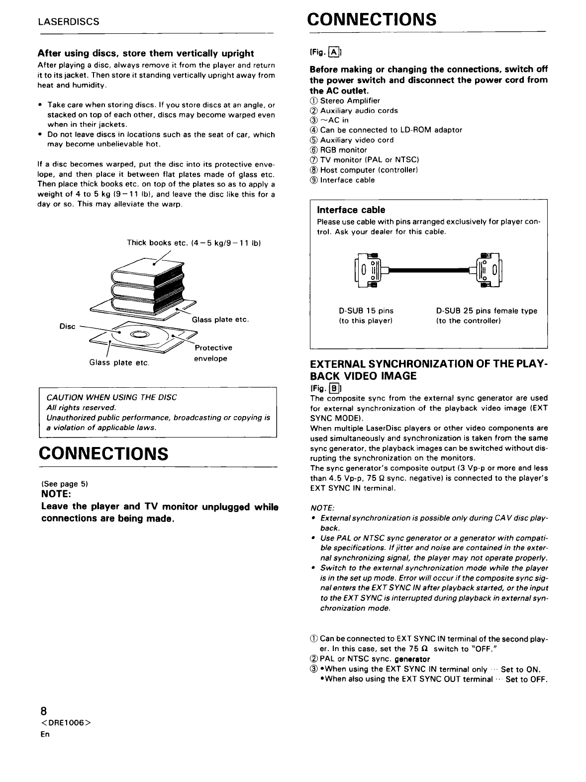
CONNECTIONS
PANEL FACILITIES ·
························6
........
6
. 7
············
7
8
.....................
9
OPERATION ·
..
····················
......
·....······················....····..
16
OPERATION
WITH
THE OPTIONAL REMOTE
CONTROL
UNIT·······························································
17
OPERATION
WITH
THE OPTIONAL VIDEO DISC
BAR-CODE
READER·························································
20
TROUBLESHOOTING
······················································
21
INTERFACE CONNECTOR
TERMINALS·····
··
····· · · ······· ··
12
SPECIFICATIONS
............................................................
23
FUNCTION SWITCHES ·
FEATURES
PLAYBACK
OF
BOTH
PAL
AND NTSC DISC
POSSIBLE
The
format
(PAL/NTSC)
of
the
loaded disc is
identified
and
output
of
PAL signal
or
NTSC signal is
selected
automatically.
EQUIPPED WITH RS-232C
The
RS-232C,
which
is
the
most
common
computer
interface,
is
provided. There are
no
conventional,
complicated
interfaces. Con-
trol
programs
can be
developed
in a
short
time
through
easy
mnemonic
commands.
HIGH-SPEED RANDOM ACCESS
High-speed search is realized
with
a linear slider
mechanism.
BUil
T-IN CHARACTER DISPLAY FUNCTION
Up
to
12
lines
of
20
characters
can be displayed
at
the
same
time.
HANDLING PRECAUTIONS
DEW CONDENSATION
If
this
player
is carried
into
a
heated
room
from
outside
during
the
winter,
or
if
the
temperature
of
the
room
where
the
player
is loca-
ted
is rapidly increased
by
a heater,
etc.,
the
lens or
the
operation
section
becomes
covered
with
dew.
When
this
occurs,
signal read
out
playback
cannot
be
performed
by
the
laser beam.
Depending on
the
degree
of
dew
condensation,
leave
it
for
1-2
hours
at
room
temperature
to
eliminate
dew
condensation
and
allow
playback
to
be
performed.
Also,
increase
the
room
temperature
gradually
during
winter
so
that
dew
condensation
does
not
occur,
then
turn
the
power
on.
Dew
condensation
sometimes
occurs
during
summer
when
air
from
an air
conditioner
hits
this
player.
If
this
occurs,
change
the
installation
location.
6
<DRE1006>
En
13
RGB
DECODER
BUil
T
IN
Direct
connection
can be made
to
an
RGB
monitor.
EXTERNAL SYNCHRONIZATION (During
CAV
disc
playback)
Horizontal/Vertical
lock
in
composite
signal
from
an
external
source
is possible because
the
unit
is equipped
with
a
sync
signal
input
terminal.
Also
possible is
synchronous
playback
such as
multi-display.
TRANSPORTATION
Precautions
should
be
taken
when
this
player
is
transported
so
that
no
vibration
or
impacts
are applied or
that
it
is
not
dropped.
Keep
heat
or
water
away
from
this
player
when
it
is
transported.
Also, be sure to remove all discs when this player
is
transported since the disc might be scratched
or
the
player might be damaged.
~--
Items With Specific Precautions
--~
Do
not move the player during playback.
Since
the
disc
rotates
at
high
speed
during
playback,
the
disc
will
be
scratched
if
the
player
is
lifted
or
moved
during
play-
back.
When
the
player is
moved,
stop
playback
and
remove
the
disc
first.
Also,
when
the
player
is carried,
the
disc
should
be
removed
first.