PIONEERPOS CYPRUS Core Pentium-Series User manual

Manual for CYPRUS (V1.0) (Core Pentium & Core i-Series) Page 1
User Manual
CYPRUS
Core Pentium & Core i-Series
For further assistance, contact us:
Tel : 909-468-9757 option 2
Web : www.pioneerpos.com
Email : support@pioneerpos.com
Drivers : http://www.pioneerposftp.com

Manual for CYPRUS (V1.0) (Core Pentium & Core i-Series) Page 2
Important Note
This manual is ONLY intended for Cyprus system with Part Number below:
QCxxxxxxxxxx
SCxxxxxxxxxx
UCxxxxxxxxxx
WCxxxxxxxxxx
Disclaimer
Information in this document is subject to change without notice. PioneerPOS shall not be liable for technical or editorial
errors in this document.
This manual contains proprietary information which is protected by copyright. No parts of this document may be
photocopied, reproduced, or translated to another language without prior written consent of Pioneer POS Solutions Inc.
Trademarks used in this manual:
PioneerPOS and PioneerPOS Logo are trademarks of Pioneer POS Solutions Inc.
Microsoft Windows, Windows are trademarks of Microsoft Corporation.
© 2015 PioneerPOS Solutions Inc. All rights reserved.
Target Audience
This Manual is written for technically qualified personnel. It is not intended for general audiences.
Warranty Exclusions
The warranty will NOT apply to damages caused by:
Unauthorized modification or abuse.
Improper or inadequate maintenance by customer.
Conventions
The following conventions are used in this manual:
[Warning]
A WARNING message indicates a potential for personal injury or death.
[Caution]
A CAUTION message indicates potential damage to hardware or loss of data
[Note]
A NOTE contains additional important information to help you in servicing the system.

Manual for CYPRUS (V1.0) (Core Pentium & Core i-Series) Page 3
Table of Content
Table of Content....................................................................................................................................................................3
Introduction ...........................................................................................................................................................................4
About this guide....................................................................................................................................................................4
System specification ............................................................................................................................................................5
Section A: Getting started....................................................................................................................................................6
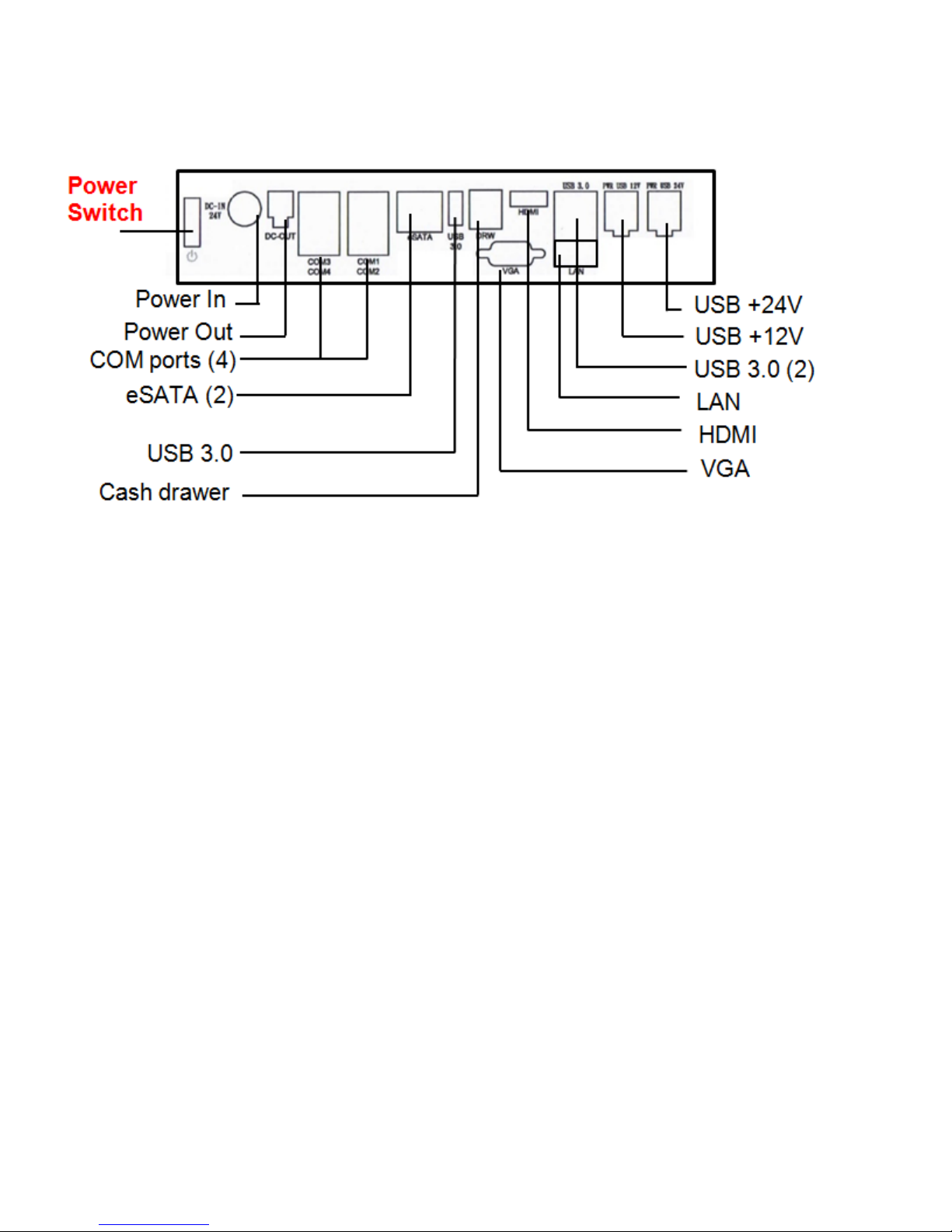
Chapter 1: Terminal overview, communication ports, and peripherals............................................................................. 6
Chapter 2: Setting Up Terminal........................................................................................................................................... 9
Section B: Using Touchscreen Terminal ..........................................................................................................................12
Chapter 3: Touch screen calibration (if needed) .............................................................................................................. 12
Chapter 4: Network........................................................................................................................................................... 15
Chapter 5: Serial port (RS232, COM ports) ....................................................................................................................... 17
Section C: Using Accessories ...........................................................................................................................................20
Chapter 6: Using Customer Display/Rear Display............................................................................................................. 20
Section D: Solving problems .............................................................................................................................................22
Chapter 7: Before working on your system ...................................................................................................................... 22
Chapter 8: Common Problems.......................................................................................................................................... 23
Chapter 9: Troubleshooting Accessories .......................................................................................................................... 29
Section E: System Board description...............................................................................................................................30
Chapter 10: System Board Layout..................................................................................................................................... 30
Chapter 11: System Board Jumper Settings...................................................................................................................... 31

Manual for CYPRUS (V1.0) (Core Pentium & Core i-Series) Page 4
Introduction
PioneerPOS CYPRUS terminal is an AIO touch screen computer system that is perfect fit for space-constrained
applications such as restaurant, hospitality, information service, medical, and the likes. PioneerPOS manufactures All-in-
One touch screen systems with built-in PC, as well as touch monitor with different sizes.
About this guide
This manual is intended to be use as a reference for field service as well as workshop repair. It is prepared to our best to
represent the current version of our production. In our effort to continuously our product, there may be changes that are
not represented in this manual. Please contact us directly if further assistance is required.
Please have the Serial Number and Part Number Ready before contacting our support line so they can assist you
efficiently.

Manual for CYPRUS (V1.0) (Core Pentium & Core i-Series) Page 5
System specification
Display
15” LED-backlit LCD, 1024 x 768 (optimal resolution)
Touch Screen Option
Resistive, PCAP Multitouch
Processor
Intel 4th Generation (Haswell) Core Pentium / i3 / i5 / i7
Memory
up to 8GB (depending on processor type)
Storage
SATA, 2.5” Hard Drive, Solid-state Disk
Operating System
Windows 7, Pos Ready 7, Windows 8.1 Industry Pro, Windows 8.1 Industry Pro for
Retail, Linux
Network/Ethernet
10/100/1000 BaseT
Wi-Fi (wireless)
RF 802.11 a/g/n (optional)
Serial Port
4
USB Port
2 x USB 2.0, 3 x USB 3.0
PoweredUSB, +12 volts
1
PoweredUSB, +24 volts
1
Parallel Port
Optional
Cash Drawer Port
1 (can be connected to 2 cash drawers with adapter cable)
Speakers
2 Watts, Stereo (optional)
Mounting Options
Desktop Base (power supply adapter built-in)
V-base
Wall mount
VESA 100 mount (built-in)
Security Lock
Bolted , or Kensington MicroSaver
Bezel Color
Standard: Silver
Option: Black
Operating Temperature
0C to 40C
Operating Humidity
20% to 80%
Power Supply
External, 150W, AC 100-240V
Agency Approvals
FCC A, CE, CCC
Integrated Add-ons
(optional)
Magnetic stripe or Barcode slot reader
Fingerprint /Biometric reader (DigitalPersona)
Rear customer display or 10" LCD
Barcode scanner/Imager
Proximity RFID reader
Privacy Filter

Manual for CYPRUS (V1.0) (Core Pentium & Core i-Series) Page 6
Section A: Getting started
Chapter 1: Terminal overview, communication ports, and peripherals
1.1 Identifying controls and ports

Manual for CYPRUS (V1.0) (Core Pentium & Core i-Series) Page 7
1.2 Communication ports

Manual for CYPRUS (V1.0) (Core Pentium & Core i-Series) Page 8
1.3 Optional peripherals
Magnetic strip reader Biometric (fingerprint) reader
Part number: 4GB-U39 Part number: 49-FP-URU4S-U2
Second display monitor (10-inch) 2D Imager (Barcode scanner)
Part number: 1H000002A1 Part number:
4G-B1-DS457DLU1 (Driver’s license parsing)
4G-B1-DS457SRU1 (Short range)
Customer Display (2x20 VFD Line display) Wall-mounting Plate
Part number: 46B-RCRJ-XXX Part number: 1GB-WALL01
(XXX: Emulation type, call support for part number)
Image
not available

Manual for CYPRUS (V1.0) (Core Pentium & Core i-Series) Page 9
Chapter 2: Setting Up Terminal
2.1 Standard base model

Manual for CYPRUS (V1.0) (Core Pentium & Core i-Series) Page 10
2.2 V-base model

Manual for CYPRUS (V1.0) (Core Pentium & Core i-Series) Page 11
2.3 Connecting network
The LAN network port is located on the I/O Panel. Cyprus also comes with optional build-in wireless card.

Manual for CYPRUS (V1.0) (Core Pentium & Core i-Series) Page 12
Section B: Using Touchscreen Terminal
Chapter 3: Touch screen calibration (if needed)
[NOTE]
Following instructions are only applicable to RESISTIVE type touch panel. PCAT (projective capacitive) type touch panel
will NOT require calibration in either Windows 7 or Windows 8.1 operating environment.
3.1 Calibration on Windows 7 or POS Ready 7
Cyprus’s Touch Screen can be operated with finger or soft stylus. If you have re-installed the driver software, you need to
open TouchKit to re-calibrate the touch screen:
1. Go to Start -> All Programs -> eGalaxTouch -> Configure Utility.
2. Click on “Tools” when you need to calibrate.
3. Perform 4 point calibration when you see the calibration screen. Use a touch screen stylus pen or your finger to
touch each point for about 1-2 seconds until you hear a “beep” sound.
[Note] Linearization is not needed for regular use.

Manual for CYPRUS (V1.0) (Core Pentium & Core i-Series) Page 13
3.2 Calibration on Windows Pro 8.1 or Windows Embedded Industry Pro 8.1 or Windows
Embedded Industry Pro Retail 8.1
1. On desktop top, hit the Windows Icon either on keyboard or lower left corner.
2. Type out “Tablet PC Settings”
3. Click on the Icon for Tablet PC Settings
4. Here you will be given the option to run calibration:

Manual for CYPRUS (V1.0) (Core Pentium & Core i-Series) Page 14
5. Tap the center (DO NOT Press and HOLD) of cross hair as it moves around the screen.

Manual for CYPRUS (V1.0) (Core Pentium & Core i-Series) Page 15
Chapter 4: Network
4.1 Wired network
Standard Cyprus comes with on-board Intel Network controller. For regular network usage, you just need to plug in the
network cable and it should work. In case you need to check your network setting, you can follow the instruction below:
1. Start -> Control Panel -> System
2. Under “Hardware Tab”, select “Device Manager”
3. Expand “Network adapters” selection.
4. In “Intel 82567M Gigabit Network Connection Properties”, you can check items such as: MAC Address, IP
Address, Link Status.
5. To perform Network Test and Diagnostic under the table “Link Speed”. Then, click on “Diagnostics”.

Manual for CYPRUS (V1.0) (Core Pentium & Core i-Series) Page 16
4.2 Wireless network
4.2.1 For system installed with Intel MiniPCI/MiniPCI-E wireless card
1. Go to Start -> Program -> Intel PROset Wireless.
2. Click on “Intel PROset Wireless” to setup wireless utility.

Manual for CYPRUS (V1.0) (Core Pentium & Core i-Series) Page 17
Chapter 5: Serial port (RS232, COM ports)
5.1 Serial port location and pin assignment
Cyprus comes with four RS232 Serial port on I/O Panel. The serial ports are using 8-Pin RJ45 connector.
Picture: Serial Port (RS232) Location highlighted in RED rectangular box.
Table: Pin Assignment for RS232 Serial Port
PIN
Serial Port Signal
Description
1
DCD
Data Carrier detect
2
RX
Receive data
3
TX
Transmit data
4
DTR
Data Terminal
Ready
5
GND
Signal Ground
6
DSR
Data Set Ready
7
RTS
Request to send
8
CTS
Clear to send

Manual for CYPRUS (V1.0) (Core Pentium & Core i-Series) Page 18
5.2 Using RJ45 to DB9 adapter with serial port/COM port
If you are using devices with DB9 Connector, you can use RJ45 to DB9 adapter. Please see picture below:
Picture: RJ45 Male to DB9 Male adapter (P/N: 30-326F)
Table: Pin assignment for RJ45 Male to DB9 Male adapter (P/N: 30-326F)
RJ45 Male
DB 9 Male
Pin 1
Pin 1 (Data carrier detect)
Pin 2
Pin 2 (Receive data)
Pin 3
Pin 3 (Transmit data)
Pin 4
Pin 4 (Data Terminal Ready)
Pin 5
Pin 5 (Signal ground)
Pin 6
Pin 6 (Data set ready)
Pin 7
Pin 7 (Request to send)
Pin 8
Pin 8 (Clear to send)
Pin 9
---

Manual for CYPRUS (V1.0) (Core Pentium & Core i-Series) Page 19
5.3 Power supplied by serial port/COM port
By default, COM Port 2 does not supply power. It can be set to supply +5V or +12V power by modifying jumper setting on
Jumper COM2_DCD and COM2_RI on the System Board. Please see table below for setting of these two jumpers. Power
will be available on Pin 1.
[Warning] If COM Port 2 is set with power, users shall not plug in other devices to that port. Failure to do so may result in
damages on connected devices.
COM2_DCD: COM2 DCD Jump setting
Connector: HEADER 2X3P G/F 2.0MM BLK S/T
Jumper: MINI JUMPER 2P,2.0MM,F,SMT
COM2_ RI: COM2 RI Jump setting
Connector: HEADER 2X4P S/T,2.0mm,DIP
Jumper: MINI JUMPER 2P,2.0MM,F,SMT
1-2
12V
3-4
5V
5-6
RI2#
7-8
GND
(default)
[Note] Call PioneerPOS tech support at 909-468-9757 or email support@pioneerpos.com for detail info on how to make
changes.
1-2
12V
3-4
5V
5-6
DCD
(default)
Pin 1
Pin 1
Pin 2

Manual for CYPRUS (V1.0) (Core Pentium & Core i-Series) Page 20
Section C: Using Accessories
Chapter 6: Using Customer Display/Rear Display
(optional, part number: 46B-RCRJ-XXX)
Unless specified, standard Rear Display/Customer Display shipped from PioneerPOS is set to AEDEX protocol by default.
6.1 Protocol/emulation supported
Pioneer POS rear display/customer display supports a few different protocols. The supported protocols are:
General
AEDEX
UTC standard
UTC Enhanced
Epson
CD7220 (CD5220-II)
PD3000
6.2 Reprogram rear display protocol/emulation
Please obtain the utility to reprogram Rear Display Protocol by contacting PioneerPOS Technical Support.
If you need to re-program the rear display firmware, you may connect the display to COM1/COM2/COM3/COM4 or COM5.
After that, run the “PPOSx.EXE” (x stands for version number, for example: “PPOS4.exe”) utility. Please follow the steps
below when after PPOS program is loaded:
1. Enter the Com port that is connected to your rear display (You can choose COM1, COM2, COM3, COM4, or
COM5).
2. Please input Command code number for the protocol that you wish to change to at the text filed after the line
“Please Input Command Code Number”.
This manual suits for next models
1
Table of contents
Other PIONEERPOS Payment Terminal manuals
Popular Payment Terminal manuals by other brands

First Data
First Data RP10 Quick setup guide

VeriFone
VeriFone V240m Installation and user guide

Coinco
Coinco Vantage Series Installation & operation guide

Spire
Spire SPw60 Quick reference guide

SIX Payment Services
SIX Payment Services Worldline YOMANI AUTONOM quick guide

Innovative Control Systems
Innovative Control Systems Auto Sentry Petro installation guide