3
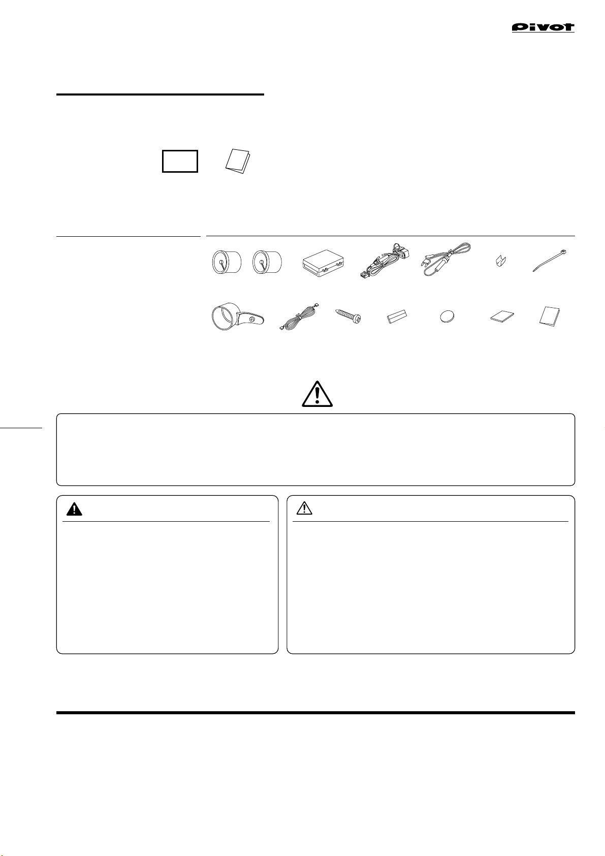
1-pin Connector Fuse Power Cable
OBD Cable Diagnostic Monitoring
Connector
Yellow Red
Red
①Remove the standard tachometer
Remove the screw from the hole at the
back of the tachometer.
*Put the bolt store in a safe place.
Line up the screw holes on the original
tachometer with the screw holes on
the meter holder and lightly fasten with
the double-sided tape.
*Do not press to strongly on the tape;
it may become difficult to remove.
When installing the 52X-MN please
make adjustments to line up the
meters on each side.
Unscrew the two screws (torque screw T30 x 2) from the base at the back of the tachom-
eter and remove it by pulling it forward. (As the wiring for the tachometer is connected to
inside the steering column it cannot be removed. Carry out all operations with the wiring
pulled out but connected.)
*Make sure not to lose any removed parts.
Affix the supplied meter holder to the back
of the standard tachometer.
Remove
②Unscrew the screws at the
back of the tachometer
⑥Return the tachometer
to its original position
Return the tachometer to its original
place by going in the reverse order
from ①above, and securely fasten
with the two screws.
Tachometer
(Backside)
Two screws
(torque screw
T30 x 2) Cable
Cable
Installing without
removing tachometer
Tachometer
(Backside)
Hole
Two screws
①Locate the Diagnostic Monitoring
Connector Position
①Remove the Cover of the Fuse Box
④Lightly Fasten the Meter
Holder
Affix the provided double-sided tape
(round) to the two places as shown in the
figure to the right.
③Affix Double-sided Tape to
the Stay on the Meter Holder
Use the provided tap screws to fasten.
Meter Holder (Backside)
Tachometer (Backside)
Tap screw
(included)
⑤Fix the meter holder with
the screws
⑦Fasten the meter to the
meter holder
Affix the provided cushion tape to two
places on the sides of the meter. Pull
the meter cable through the hole at the
back of the meter holder and insert it
into the 5-pin connector at the back of
the meter. After having decided the
angle press the meter into the holder
at finish the installation.
Double-sided Tape
(round)
Diagnostic Monitoring
Connector
Diagnostic Monitoring
Connector
Diagnostic Monitoring
Connector
Diagnostic Monitoring
Connector
Diagnostic Monitoring
Connector
Diagnostic Monitoring
Connector
Open
Open
Cover
Cover
②Open the Cover ③Completely insert the OBD
Connector
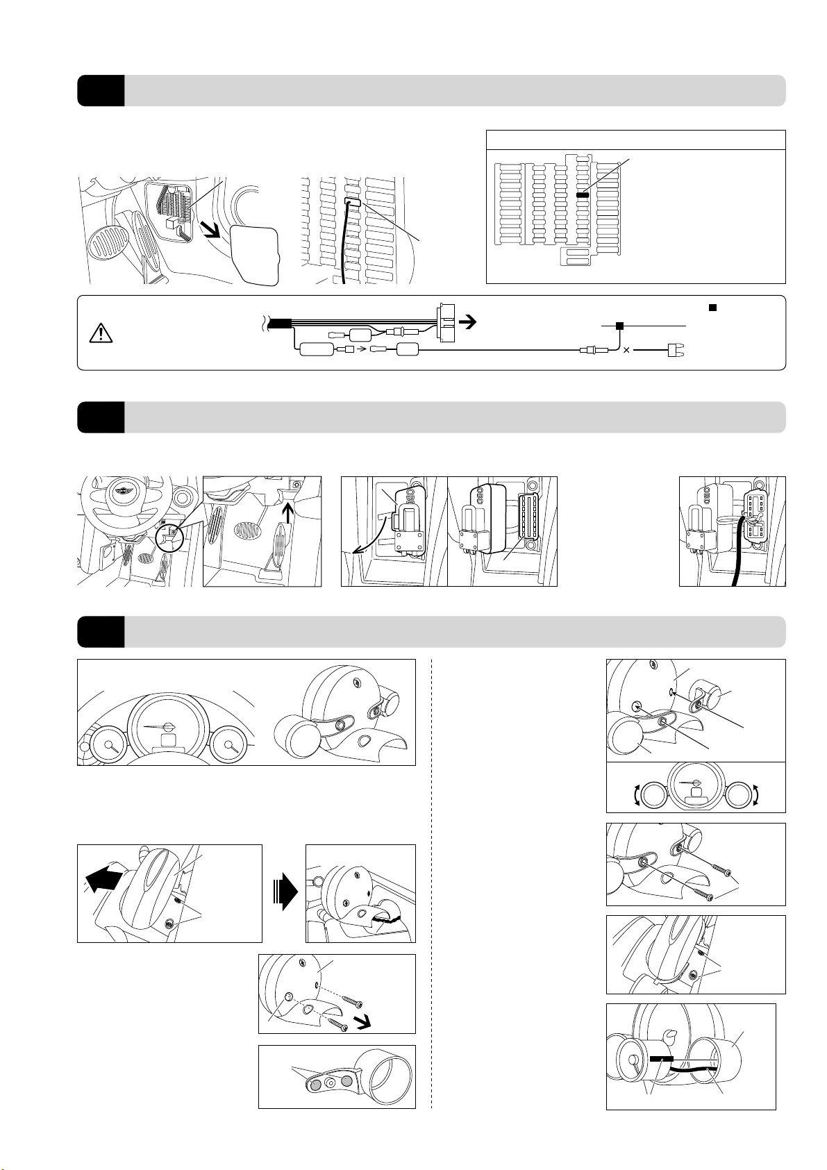
②Insert the Fuse
Fuse Box
Fuse Box
Cover
Remove the fuse for IGN (12 V with key
switch ON), and insert the 7.5 A mini-
fuse from the fuse power cable.
Use a flathead screwdriver or such tool to remove
the cover of the fuse box found on the side of the
panel to the right of the steering wheel.
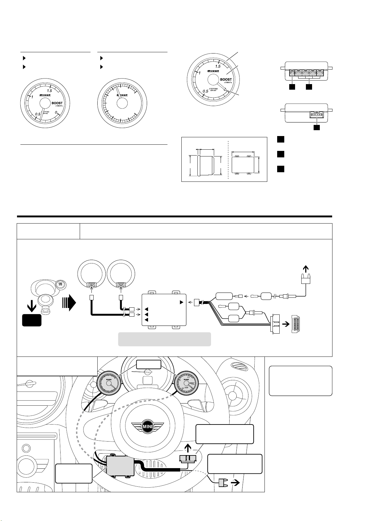
Connecting the OBD Connector
2
Fastening The Meter
3
Connecting to a Power Source
1
IGN
Cut Fuse
=Cut connector
(or soldering)
If you are unable to get power
from the fuse box, please
wire directly to IGN (12V with
key in ON position).
Insert the OBD connec-
tor to the diagnostic
monitoring connector
from the Unit.
Meter Holder
(Backside)
Cushion tape (two places)
Meter Holder
Meter Cable
(Front of the fuse box)
Position = 4th column from the left
and 5th row from the top
Number = 32 or 34
Capacity = 7.5A
Ex: BMW MINI COOPER S SV16 (steering wheel on right, 2010 MODEL)
*If you wish to get power from a fuse
other than the 7.5A mini-fuse, please
purchase separately.
Example of a place of specific fuse
Fuse
(included)
Fuse
(included)
(Not as normal
power source)
The following is just one example of wiring to the fuse box of a BMW MINI COOPER S SV16 (steering
wheel on right). If your model is different and you are unsure of how to connect please contact your dealer.