4PIVOT CORPORATION 87-3, Shimookada Okada, Matsumoto-shi, Nagano, 390-0313 JAPAN
BOOST
DUAL GAUGE
-0.8
-0.4
0
0.5
1.5
1.0
x100 kPa
BOOST
DUAL GAUGE
-0.8
-0.4
0
0.5
1.5
1.0
x100 kPaDUAL GAUGE
●When the key is turned ON the needle will move to the extreme left several times
for searching position. Then it will move to the maximum value and finally to
reading for current measurement item.
●Due to analyzation time for the car data transmission it may take up to a few
seconds from engine start before opening demo.
14523
Troubleshooting
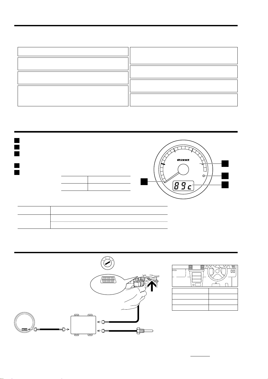
This product’ s boost meter reads absolute pressure and may differ from a meter using relative pressure.
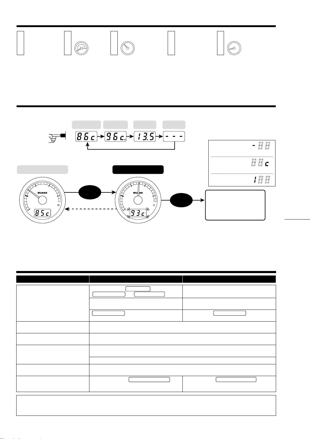
Switching The Display
Switching The Digital Display
Display and Reset the Peak Value
Boost Auto Peak Display
Basic Operation
Opening Demo
●Due to analyzation time for the car data transmission, the
illumination may remain on for up to 3 minutes even after the
engine has been turned off; this is normal and no effect on
the vehicle performance.
Turning off the Display
Display Each Mode Meter OFF
*1. Not displayed without temperature sensor.
*2. For some car models the voltage cannot be
displayed or “
--
.
-
” will appear. For details,
see the Fitting List.
Water Temp Oil Temp*1Voltage*2Boost
Auto Peak
(Lighting)
(Lighting) (Blinking)
(Blinking)
(decimal point is lightning)
Real-time Display Peak Value Display
Reset the Peak Value
Only the peak value on display
will be reset. This will return to
the Real-time Display for the
currently displayed mode.
Press
Switch Press
Switch
Water Temperature / Oil Temperature
Reading the Display
-
35 〜
-
1°C
0〜99 °C
100 〜150 °C
The key switch is set to ON, Needle of
Boost shows minus value.
Absolute pressure sensor shows the value which subtracted atmospheric pressure.
(Example : 700m above sea level = Minus 8kPa)
Trouble Possible Causes Possible Solutions
Does not work with Engine start.
Please check the “Fitting List” .
This is due to a special characteristic of the meter and is not a malfunction.
Because after changing displays, if the car’ s engine is turned off within 3 seconds, the new setting will not be
stored, make sure to wait at least 3 seconds before turning the engine off.
Please reconfirm whether wiring and connections
are correct or not.
Please reconfirm Temperature sensor whether
wiring and connections are correct or not.
The unit has been installed into an incompatible car
model.
Due to the ECU information received, the displayed values on this product may differ from those of standard
or other meters.
The displayed values are different from
the standard meter.
Before the opening demo starts the
needle briefly moves.
OBD Connector was connected when the key
switch was set to OFF, or car battery was changed.
Connect again OBD Connector when the key
switch is set to ON (engine start).
※Our products have already been recognized as our Industrial Property or are in the process of receiving Industrial Property status.
※We plan in the near future to take all possible legal measures to protect against unfair competition from look-alike products using similar designs,
regulating characteristics, circuitry and circuitry layout.
※We strictly prohibit the unlicensed use of the PIVOT trademark and the unauthorized use of PIVOT User’s Manual.
Key Switch ON
(Engine start)
Opening Demo Key Switch OFF
(Engine stop)
for 3Seconds
for 3Seconds
The needle stops
in the vicinity of
lowest value.
With no operation
5Seconds
*Peak readings are reset when the key is turned OFF.
*For Boost, Vacuum, RPM, Water Temperature and Oil
Temperature the high will be shown and for Voltage the low
will be displayed.
*If you wish to check the loss of voltage upon operation of
the starter, turn the key to the ON position and after the
digital display comes on, operate the starter.
The first place on the left
shows“
-
” (minus).
The third place from
the left shows “c” (Celsius).
Numerical Value Only.
Poor connection of Temperature sensor or
breaking of wire.
Poor connection of Gauge cable ,
7-pin Connector and OBD Connector .
The Oil Temperature displays do not
change from
---
. , or do not show the
value with connecting the sensor.
Upon starting up, the unit will start in
the newly changed display.
●Display ”
---
” on the multi-digital display when the value in negative pressure
range.
●Display peak value on the multi-digital display if the value in positive pressure
range. Display ”
---
” if the value in negative pressure range more than 3 seconds .
Press switch to change
the multi-digital display
in operation