1
SET
rpm
PEAK
REV COUNTER
Zip Ties
× 5
Allen
Wrench
Double-sided
Tape
REV COUNTER
SHIFT LAMP & REV COUNTER for Pros
OBD2
Power Cable
with fuse 3A
Shift Lamp
User’s guide
ECU wiring
diagram list
Controller
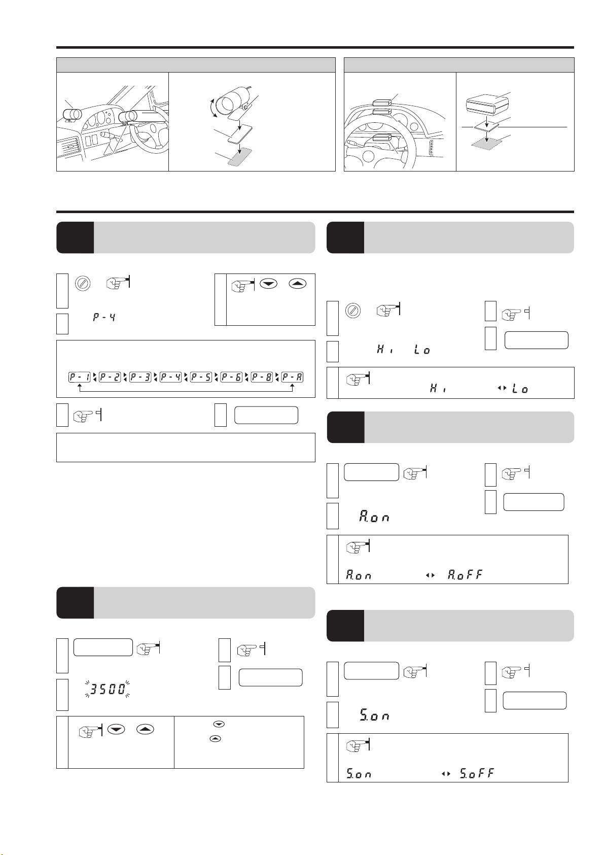
■ Shift Lamp
Shift lamp lights up when the set rpm is reached.
・Ultra bright LED is easy to see even in full daylight.
・For night driving select auto low lighting or synchronize with parking lights.
・High quality aluminum machined body with swivel neck.
■ Digital Tachometer
High precision display for setting shift lamp and viewing rpm.
・High precision display of engine rpm up to 9999 in 1 rpm units.
・Shift lamp settings can be made in units of 100 rpm.
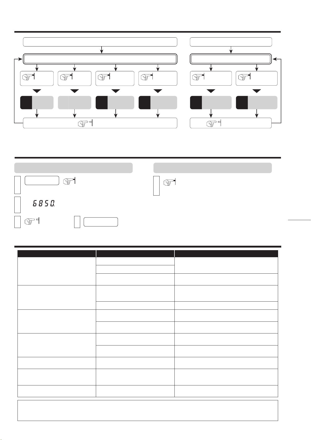
・View real time and peak engine rpm.
・Compact design needs no space.
■ Alarm
Alarm sounds at shift point for 0.5 seconds.
■ Easy Installation
Can be easily installed in some model TOYOTA and DAIHATSU cars
directly by connecting to the diagnostics connector. Other models can be
connected to the ECU.
■ Compatible Vehicles
12 V Gasoline Engine Cars (some diesel engine models)
For 1・2・3・4・5・6・8 cylinder models.
REV COUNTER RCX
■ Size
50
32
46
60
(Front) (Backside)
SET( ) switch
PEAK( ) switch
Display RPM and each setting display
Change each setting
Peak and change each setting
For Automatically low lighting
1
12 6
34 5
2
3
5-pin Connector Connect to the 5-pin Connector of Power cable
2-pin Connector Connect to the 2-pin Connector of Shift Lamp
Light sensor
4
5
6
Part Names of the Controller
20
(Shift Lamp) (Controller)
[Unit:mm]
●Do not work in areas where there is excessive exhaust.
Due to vehicle exhaust emission poisoning or fire may result in a damage to
humans.
●Please securely fasten the product to a stable place.
It is very dangerous if, while in use, the product falls off and interferes with braking.
●Do not crush the cable.
Please be careful that the cable does not get crushed by the seat rail or car door
steel plate, nor cut by any sharp steel plate as this may cause a poor connection or
an electric short leading to fire or other danger.
●Do not operate while driving.
Operating or checking the display during driving may cause an accident; please use
with the utmost consideration for safety.
●Please be sure to store bundle away all wires with tape, etc...
It is very dangerous to pull tangled wires by force or allow tangled wires to interfere
with driving.
●This product is for DC12V cars;
Installation cannot be carried out on cars with other voltage batteries.
●Just after installation do not exert any strong force on the product.
When double-sided tape is used for an installation be warned that when hot the
tape temporarily losses adhesiveness.
●Do Not Use Chemical Cleansers.
If the unit gets dirty please wipe with a soft cloth to remove any dirt. Do not use
chemical cleansers such as thinner, benzene, or alcohol.
●Do not install the product in any place subject to high temperature
or any place where water may be splashed.
●Make sure to replace all screws and parts to their original place.
●Do not install the product in a place where it will cause distraction.
●Do not, in any manner, process, take apart, or make changes to
this product.
WARNING Improper use or disregard of these warnings may
result in the injury or death of people. CAUTION Improper use or disregard of these warnings may
cause injury to persons, damage the product and
other things.
USER’S MANUAL
(RCX As of October, 2013 No.1)
Contents Please check the contents of the package
Product +
●If this product is given to
another user, make sure to
include this User’s Manual.
Thank you for purchasing this PIVOT product.
Please read this manual carefully and keep it for future
reference.
Contents / WARNING / CAUTION ……… 1
Features …………………………………… 1
Connecting The Wires …………………… 2
Installing The Product …………………… 3
Settings……………………………………… 3
Basic Operation …………………………… 4
Display The Peak Value and Reset …… 4
Troubleshooting …………………………… 4
Features
Cut Connectors
× 4
White
extension
cord
Earth
terminal