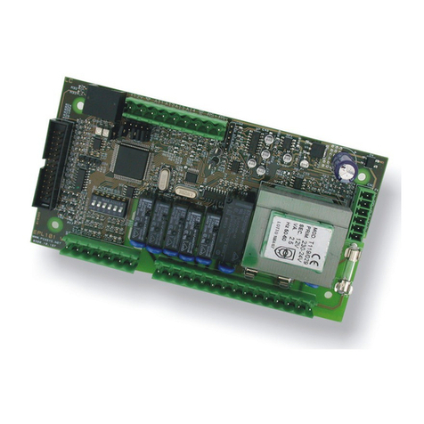
Pixsys MCM260X User manual

MCM260X
Modbus RTU - CANopen expansion module
User manual - Manuale d'uso


Table of contents
1 Safety guidelines.......................................................................................................................................................... 7
1.1 Organization of safety notices.................................................................................................................. 7
1.2 Safety Precautions ....................................................................................................................................... 7
1.3 Precautions for safe use.............................................................................................................................. 8
1.4 Environmental policy / WEEE .................................................................................................................... 8
2 Composition of acronym ........................................................................................................................................... 9
3 Technical data............................................................................................................................................................... 9
3.1 General characteristics ............................................................................................................................... 9
3.2 Hardware characteristics ........................................................................................................................... 9
3.3 Software features....................................................................................................................................... 12
4 Dimension and installation..................................................................................................................................... 12
4.1 Electric connections................................................................................................................................... 13
4.2 Connection to the communication line................................................................................................ 18
5 Device SET-UP ............................................................................................................................................................. 18
5.1 Numeric indicators (internal display).................................................................................................... 18
5.2 Meaning of the status lights (LED) ......................................................................................................... 19
5.3 Changing the configuration parameters from the terminal........................................................... 19
5.4 Changing to the configuration parameters from the MyPixsys app.............................................20
5.5 Table of the configuration parameters that can be accessible from the terminal and via the
MyPixsys app............................................................................................................................................... 21
5.6 Restore to factory settings........................................................................................................................22
6 Table of the configuration parameters for the models MCM260X-1/2/3/4AD ............................................22
6.1 UNIT A - GENERAL CONFIGURATION .....................................................................................................23
6.2 UNIT B - ANALOG INPUTS .........................................................................................................................24
6.3 UNIT C - DIGITAL INPUTS...........................................................................................................................25
7 Table of the configuration parameters for the model MCM260X-5AD.........................................................26
7.1 UNIT A - GENERAL CONFIGURATION .....................................................................................................26
7.2 UNIT B - ANALOG INPUTS .........................................................................................................................27
7.3 UNIT C - ANALOG OUTPUTS.....................................................................................................................29
8 Table of the configuration parameters for the model MCM260X-9AD.........................................................30
8.1 UNIT A - GENERAL CONFIGURATION .....................................................................................................30
8.2 UNIT B - ANALOG INPUTS ......................................................................................................................... 31
8.3 UNIT C - ANALOG OUTPUTS.....................................................................................................................33
8.4 UNIT D - DIGITAL INPUTS ..........................................................................................................................34
9 Modbus RTU ................................................................................................................................................................35
9.1 Characteristics of the Modbus RTU slave protocol.............................................................................35
9.2 Modbus RTU communication areas......................................................................................................35
10 CANopen ......................................................................................................................................................................44
10.1 SET-UP of slave CANopen node ..............................................................................................................44
10.2 Slave CANopen node operation .............................................................................................................44
10.3 EDS Files........................................................................................................................................................44
11 CANopen in detail......................................................................................................................................................44
11.1 Object Dictionary.......................................................................................................................................45
11.1.1 CANopen communication model ...................................................................................................46
11.1.2 CANopen Pre-defined Connection Set ........................................................................................... 47
11.1.3 CANopen identifier distribution.......................................................................................................48
11.1.4 CANopen boot-up procedure ...........................................................................................................48
11.1.5 Communication profile: initialization............................................................................................48
11.1 Communication Profile Area...................................................................................................................49
11.1.1 Device Type ...........................................................................................................................................50
11.1.2 Error Register.........................................................................................................................................50
11.1.3 Pre-defined Error Field........................................................................................................................50
11.1.4 COB-ID SYNC message....................................................................................................................... 51
11.1.5 Communication Cycle Period ........................................................................................................... 51

11.1.6 Manufacturer Device Name.............................................................................................................. 51
11.1.7 Manufacturer Hardware Version..................................................................................................... 51
11.1.8 Manufacturer Software Version.......................................................................................................51
11.1.9 Node ID .................................................................................................................................................. 51
11.1.10 Guard Time............................................................................................................................................ 51
11.1.11 Life Time Factor.................................................................................................................................... 52
11.1.12 Store Parameters .................................................................................................................................52
11.1.13 Restore Default Parameters ..............................................................................................................52
11.1.14 COB-ID Emergency Object ................................................................................................................52
11.1.15 Inhibit Time Emergency Object........................................................................................................ 52
11.1.16 Producer Heartbeat Time ..................................................................................................................52
11.1.17 Identity Object...................................................................................................................................... 53
11.1.18 Error Behaviour ....................................................................................................................................53
11.1.19 Receive PDO Communication Parameter......................................................................................53
11.1.20 Receive PDO Mapping Parameter ...................................................................................................54
11.1.21 Transmit PDO Communication Parameter ................................................................................... 55
11.1.22 Transmit PDO Mapping .....................................................................................................................56
11.2 Manufacturer Specific Parameter Area.................................................................................................56
11.2.1 Device specification ............................................................................................................................56
11.2.2 MCM260X parameters........................................................................................................................57
11.2.3 Encoder/Counter calculations ..........................................................................................................58
11.2.4 Encoder/Counter preset .....................................................................................................................58
11.2.5 Encoder/Counter commands............................................................................................................58
11.2.6 Encoder counter calculations 1s ......................................................................................................59
11.2.7 Encoder/Counter calculations 100ms............................................................................................. 59
11.2.8 Status/error flags .................................................................................................................................59
11.3 Standard Device Profile Area...................................................................................................................60
11.3.1 Digital Input.......................................................................................................................................... 61
11.3.2 Global interrupt Enable Digital 8 bit............................................................................................... 61
11.3.3 Interrupt Mask Any Change 8 bit..................................................................................................... 61
11.3.4 Interrupt Mask Low-to-High 8 bit.................................................................................................... 61
11.3.5 Interrupt Mask High-to-Low 8 bit....................................................................................................62
11.3.6 Digital Output ......................................................................................................................................62
11.3.7 Error Mode Output 8bit......................................................................................................................62
11.3.8 Error Value Output 8bit ......................................................................................................................63
11.3.9 Analogue Input 16bit.......................................................................................................................... 63
11.3.10 Analogue Output 16bit ......................................................................................................................63
11.3.11 Analogue Input Interrupt Trigger Selection ..................................................................................64
11.3.12 Analogue Input Global Interrupt Enable.......................................................................................64
11.3.13 Analogue Input Interrupt Upper Limit Integer .............................................................................64
11.3.14 Analogue Input Interrupt Lower Limit Integer .............................................................................65
11.3.15 Analogue Input Interrupt Delta Unsigned..................................................................................... 65
11.3.16 Analogue Input Interrupt Negative Delta Unsigned...................................................................65
11.3.17 Analogue Input Interrupt Positive Delta Unsigned .....................................................................66
11.3.18 Analogue Output Error Mode...........................................................................................................66
11.3.19 Analogue Output Error Value Integer.............................................................................................66
11.3.20 Error Behaviour ....................................................................................................................................66
11.4 PDO transmission....................................................................................................................................... 67
11.4.1 PDO Mapping.......................................................................................................................................67
11.5 Monitoring via SYNC ................................................................................................................................. 67
11.6 Node Guarding ...........................................................................................................................................67
11.7 Monitoring via Heartbeat ........................................................................................................................68
11.8 Emergency ...................................................................................................................................................68
12 Error messages............................................................................................................................................................69

Indice dei contenuti
1 Norme di sicurezza ....................................................................................................................................................71
1.1 Organizzazione delle note di sicurezza ................................................................................................ 71
1.2 Note di sicurezza.........................................................................................................................................71
1.3 Precauzioni per l’uso sicuro .....................................................................................................................72
1.4 Tutela ambientale e smaltimento dei rifiuti / Direttiva WEEE .........................................................73
2 Composizione della sigla .........................................................................................................................................73
3 Dati tecnici...................................................................................................................................................................73
3.1 Caratteristiche generali ............................................................................................................................73
3.2 Caratteristiche Hardware......................................................................................................................... 74
3.3 Caratteristiche software ...........................................................................................................................76
4 Dimensioni e installazione ...................................................................................................................................... 76
4.1 Collegamenti elettrici................................................................................................................................77
4.2 Collegamento alla linea di comunicazione.........................................................................................82
5 SET-UP del dispositivo...............................................................................................................................................82
5.1 Indicatori numerici (display interno).....................................................................................................82
5.2 Significato delle spie di stato (Led).........................................................................................................83
5.3 Modifica parametri di configurazione da terminale.........................................................................83
5.4 Modifica parametri di configurazione da app MyPixsys..................................................................84
5.5 Tabella dei parametri di configurazione accessibili da terminale e tramite app MyPixsys .....85
5.6 Ripristino dei parametri di fabbrica.......................................................................................................86
6 Tabella parametri di configurazione per i modelli MCM260X-1/2/3/4AD....................................................86
6.1 GRUPPO A - CONFIGURAZIONE GENERALE..........................................................................................87
6.2 GRUPPO B - INGRESSI ANALOGICI ..........................................................................................................88
6.3 GRUPPO C - INGRESSI DIGITALI ...............................................................................................................89
7 Tabella parametri di configurazione per il modello MCM260X-5AD ............................................................89
7.1 GRUPPO A - CONFIGURAZIONE GENERALE..........................................................................................89
7.2 GRUPPO B - INGRESSI ANALOGICI ..........................................................................................................90
7.3 GRUPPO C - USCITE ANALOGICHE..........................................................................................................93
8 Tabella parametri di configurazione per il modello MCM260X-9AD ............................................................94
8.1 GRUPPO A - CONFIGURAZIONE GENERALE..........................................................................................94
8.2 GRUPPO B - INGRESSI ANALOGICI ..........................................................................................................95
8.3 GRUPPO C - USCITE ANALOGICHE.......................................................................................................... 97
8.4 GRUPPO D - INGRESSI DIGITALI...............................................................................................................98
9 Modbus RTU ................................................................................................................................................................98
9.1 Caratteristiche protocollo Modbus RTU slave.....................................................................................99
9.2 Aree di comunicazione Modbus RTU.....................................................................................................99
10 CANopen ....................................................................................................................................................................108
10.1 SET-UP nodo CANopen slave.................................................................................................................108
10.2 Funzionamento nodo CANopen slave................................................................................................108
10.3 EDS Files......................................................................................................................................................108
11 CANopen nel dettaglio ...........................................................................................................................................108
11.1 Object Dictionary.....................................................................................................................................109
11.1.1 CANopen communication model ................................................................................................. 110
11.1.2 CANopen Pre-defined Connection Set ..........................................................................................111
11.1.3 CANopen identifier distribution..................................................................................................... 112
11.1.4 Procedura di boot-up CANopen .................................................................................................... 112
11.1.5 Communication profile: inizializzazione..................................................................................... 112
11.1 Communication Profile Area................................................................................................................. 113
11.1.1 Device Type ......................................................................................................................................... 113
11.1.2 Error Register....................................................................................................................................... 114
11.1.3 Pre-defined Error Field...................................................................................................................... 114
11.1.4 COB-ID SYNC message..................................................................................................................... 114
11.1.5 Communication Cycle Period ......................................................................................................... 115
11.1.6 Manufacturer Device Name............................................................................................................ 115

11.1.7 Manufacturer Hardware Version................................................................................................... 115
11.1.8 Manufacturer Software Version..................................................................................................... 115
11.1.9 Node ID ................................................................................................................................................ 115
11.1.10 Guard Time.......................................................................................................................................... 115
11.1.11 Life Time Factor.................................................................................................................................. 115
11.1.12 Store Parameters ............................................................................................................................... 115
11.1.13 Restore Default Parameters ............................................................................................................ 116
11.1.14 COB-ID Emergency Object .............................................................................................................. 116
11.1.15 Inhibit Time Emergency Object...................................................................................................... 116
11.1.16 Producer Heartbeat Time ................................................................................................................ 116
11.1.17 Identity Object.................................................................................................................................... 116
11.1.18 Error Behaviour .................................................................................................................................. 117
11.1.19 Receive PDO Communication Parameter.................................................................................... 117
11.1.20 Receive PDO Mapping Parameter ................................................................................................. 118
11.1.21 Transmit PDO Communication Parameter ................................................................................. 119
11.1.22 Transmit PDO Mapping ...................................................................................................................120
11.2 Manufacturer Specific Parameter Area...............................................................................................120
11.2.1 Device specification .......................................................................................................................... 121
11.2.2 Parametri MCM260X......................................................................................................................... 121
11.2.3 Conteggi encoder/Contatori ...........................................................................................................122
11.2.4 Preset encoder/Contatori.................................................................................................................122
11.2.5 Comandi encoder/contatori ...........................................................................................................122
11.2.6 Conteggi 1s encoder contatori .......................................................................................................123
11.2.7 Conteggi 100ms encoder/contatori ..............................................................................................123
11.2.8 Flags stato/errore...............................................................................................................................123
11.3 Standard Device Profile Area.................................................................................................................124
11.3.1 Digital Input........................................................................................................................................ 124
11.3.2 Global interrupt Enable Digital 8 bit.............................................................................................125
11.3.3 Interrupt Mask Any Change 8 bit...................................................................................................125
11.3.4 Interrupt Mask Low-to-High 8 bit..................................................................................................125
11.3.5 Interrupt Mask High-to-Low 8 bit..................................................................................................125
11.3.6 Digital Output ....................................................................................................................................126
11.3.7 Error Mode Output 8bit....................................................................................................................126
11.3.8 Error Value Output 8bit ....................................................................................................................126
11.3.9 Analogue Input 16bit........................................................................................................................ 127
11.3.10 Analogue Output 16bit ....................................................................................................................127
11.3.11 Analogue Input Interrupt Trigger Selection ................................................................................127
11.3.12 Analogue Input Global Interrupt Enable.....................................................................................127
11.3.13 Analogue Input Interrupt Upper Limit Integer ...........................................................................128
11.3.14 Analogue Input Interrupt Lower Limit Integer ...........................................................................128
11.3.15 Analogue Input Interrupt Delta Unsigned...................................................................................128
11.3.16 Analogue Input Interrupt Negative Delta Unsigned.................................................................129
11.3.17 Analogue Input Interrupt Positive Delta Unsigned ...................................................................129
11.3.18 Analogue Output Error Mode.........................................................................................................129
11.3.19 Analogue Output Error Value Integer...........................................................................................129
11.3.20 Error Behaviour ..................................................................................................................................130
11.4 Trasmissione PDO.....................................................................................................................................130
11.4.1 PDO Mapping.....................................................................................................................................130
11.5 Monitoraggio tramite SYNC ..................................................................................................................130
11.6 Node Guarding ......................................................................................................................................... 131
11.7 Monitoraggio tramite Heartbeat ......................................................................................................... 131
11.8 Emergency .................................................................................................................................................132
12 Messaggi di errore....................................................................................................................................................133

Manuale d’uso - MCM260X - 7
Introduction
Thank you for choosing a Pixsys instrument.
The MCM260X modules are a series of digital/analog expansions for PLC that implement the Modbus
RTU protocol with RS485 interface or the CANopen protocol.
There are 6 versions of the expansion module, in continuous voltage for the models MCM260X-1AD,
MCM260X-2AD, MCM260X-3AD, MCM260X-9AD, while for the models with relay outputs or analog
inputs/outputs MCM260X-4AD, MCM260X-5AD operation is required in low continuous and alternating
voltage.
1 Safety guidelines
Read carefully the safety guidelines and programming instructions contained in this manual before
connecting/using the device.
Disconnect power supply before proceeding to hardware settings or electrical wirings to avoid risk of
electric shock, fire, malfunction.
Do not install/operate the device in environments with flammable/explosive gases.
This device has been designed and conceived for industrial environments and applications that rely
on proper safety conditions in accordance with national and international regulations on labour
and personal safety. Any application that might lead to serious physical dama ge/ life risk or involve
medical life support devices should be avoided.
Device is not conceived for applications related to nuclear power plants, weapon systems, flight
control, mass transportation systems.
Only qualified personnel should be allowed to use device and/or service it and only in accordance to
technical data listed in this manual.
Do not dismantle/modify/repair any internal component.
Device must be installed and can operate only within the allowed environmental conditions.
Overheating may lead to risk of fire and can shorten the lifecycle of electronic components.
1.1 Organization of safety notices
Safety notices in this manual are organized as follows:
Safety notice Description
Danger! Disregarding these safety guidelines and notices can be life-threatening.
Warning! Disregarding these safety guidelines and notices can result in severe injury or
substantial damage to property.
Information! This information is important for preventing errors.
1.2 Safety Precautions
Danger!
CAUTION - Risk of Fire and Electric Shock
This product is UL listed as DIN-rail mounting process control equipment. It must be
mounted in an enclosure that does not allow fire to escape externally.
Danger!
If the output relays are used past their life expectancy, contact fusing or burning may
occasionally occur.
Always consider the application conditions and use the output relays within their
rated load and electrical life expectancy. The life expectancy of output relays varies
considerably with the output load and switching conditions.
Warning!
Devices shall be supplied with limited energy according to UL 61010-1 3rd Ed, section
9.4 or LPS in conformance with UL 60950-1 or SELV in conformance with UL 60950-1
or Class 2 in compliance with UL 1310 or UL 1585.
Warning!
Loose screws may occasionally result in fire.
For screw terminals, tighten screws to tightening torque is 0.5 Nm for 5 mm Pitch
terminal blocks or 0.25 Nm for 3.81 mm Pitch terminal blocks.

8 - MCM260X - Manuale d’uso
Warning!
A malfunction in the Digital Controller may occasionally make control operations
impossible or prevent alarm outputs, resulting in property damage. To maintain
safety in the event of malfunction of the Digital Controller, take appropriate safety
measures, such as installing a monitoring device on a separate line.
1.3 Precautions for safe use
Be sure to observe the following precautions to prevent operation failure, malfunction, or adverse
affects on the performance and functions of the product. Not doing so may occasionally result in
unexpected events. Do not handle the Digital Controller in ways that exceed the ratings.
• The product is designed for indoor use only. Do not use or store the product outdoors or in any of
the following places.
- Places directly subject to heat radiated from heating equipment.
- Places subject to splashing liquid or oil atmosphere.
- Places subject to direct sunlight.
- Places subject to dust or corrosive gas (in particular, sulfide gas and ammonia gas).
- Places subject to intense temperature change.
- Places subject to icing and condensation.
- Places subject to vibration and large shocks.
• Installing two or more controllers in close proximity might lead to increased internal temperature
and this might shorten the life cycle of electronic components. It is strongly recommended to
install cooling fans or other air-conditioning devices inside the control cabinet.
• Always check the terminal names and polarity and be sure to wire properly. Do not wire the
terminals that are not used.
• To avoid inductive noise, keep the controller wiring away from power cables that carry high voltages
or large currents. Also, do not wire power lines together with or parallel to Digital Controller
wiring. Using shielded cables and using separate conduits or ducts is recommended. Attach a
surge suppressor or noise filter to peripheral devices that generate noise (in particular motors,
transformers, solenoids, magnetic coils or other equipment that have an inductance component).
When a noise filter is used at the power supply, first check the voltage or current, and attach the
noise filter as close as possible to the Digital Controller. Allow as much space as possible between
the Digital Controller and devices that generate powerful high frequencies (high-frequency
welders, high-frequency sewing machines, etc.) or surge.
• A switch or circuit breaker must be provided close to device. The switch or circuit breaker must be
within easy reach of the operator, and must be marked as a disconnecting means for the controller.
• Wipe off any dirt from the Digital Controller with a soft dry cloth. Never use thinners, benzine,
alcohol, or any cleaners that contain these or other organic solvents. Deformation or discoloration
may occur.
• The number of non-volatile memory write operations is limited. Therefore, use EEprom write mode
when frequently overwriting data, e.g.: through communications.
• The device must be protected by:
MCM260X-1AD: 4A Fast Fuse (F)
MCM260X-2AD: 1A Fast Fuse (F)
MCM260X-3AD: 4A Fast Fuse (F)
MCM260X-4AD: 1A Fast Fuse (F)
MCM260X-5AD: 1A Fast Fuse (F)
MCM260X-9AD: 5A Fast Fuse (F)
• The MCM260X series does not require ventilation.
1.4 Environmental policy / WEEE
Do not dispose electric tools together with household waste material.
According to European Directive 2012/19/EU on waste electrical and electronic equipment and its
implementation in accordance with national law, electric tools that have reached the end of their life
must be collected separately and returned to an environmentally compatible recycling facility.

Manuale d’uso - MCM260X - 9
2 Composition of acronym
The MCM260X series includes the following models:
MCM260X-
MCM260X-1AD Power supply 12..24 Vdc
16 Static Outputs 12..24Vdc
MCM260X-2AD
Power supply 12..24 Vdc
16 Digital inputs PNP 12..24Vdc
2 Analog inputs 0...10V
3 Encoders/Counters
MCM260X-3AD
Power supply 12..24 Vdc
8 Digital inputs PNP 12..24Vdc
8 Static Outputs 12..24Vdc
3 Encoders/Counters
MCM260X-4AD
Power supply 12..24 Vdc/Vac
8 Digital inputs PNP 12..24Vdc
8 Relay outputs
2 Analog inputs 0...10V
3 Encoders/Counters
MCM260X-5AD
Power supply 12..24 Vdc/Vac
4 Universal analog inputs
2 Analog outputs 0..10V / 4..20mA
MCM260X-9AD
Power supply 12..24 Vdc
4 Universal analog inputs
2 Analog outputs 0..10V / 4..20mA
16 Static outputs 12..24Vdc / Digital inputs PNP 12..24Vdc
4 Encoders/Counters
3 Technical data
3.1 General characteristics
Displays 4 0.52 inch displays
RUN, COM LEDs and I/O status LEDs
Operating
conditions
Temperature: 0-50 °C -Humidity 35..95 Rh%
Max. altitude: 2000m
Protection IP30 container
Materials Container: Self-extinguishing polycarbonate
Front: Self-extinguishing polyamide
Weight Approximately 250 g
3.2 Hardware characteristics
3.2.a MCM260X-1AD
Power supply 12..24 Vdc ± 15% Consumption 100VA max
Digital outputs 16 static outputs 12-24Vdc Max 700mA per output
Max 3A in total for all the outputs
Communication
port
2 modes to select:
- RS485 with Modbus RTU protocol
- CAN with CANopen protocol
Galvanically isolated
Up to 115200 baud
Up to 1Mbit

10 - MCM260X - Manuale d’uso
3.2.b MCM260X-2AD
Power supply 12..24 Vdc ±15% Consumption 10VA max
Digital inputs 16 inputs PNP 12-24Vdc VIL = 4.3V
VIL = 8.0V
Encoder/Counter
inputs
3 encoders/counters superimposed on
the PNP digital inputs
32 bit resolution
Maximum frequency 80KHz
Analog inputs 2 inputs 0..10V superimposed on the
digital inputs 45000 points resolution
Communication
port
2 modes to select:
- RS485 with Modbus RTU protocol
- CAN with CANopen protocol
Galvanically isolated
Up to 115200 baud
Up to 1Mbit
3.2.c MCM260X-3AD
Power supply 12..24 Vdc ±15% Consumption 50VA max
Digital inputs 8 inputs PNP 12-24Vdc VIL = 4.3V
VIL = 8.0V
Encoder/Counter
inputs
3 encoders/counters superimposed on
the PNP digital inputs
32 bit resolution
Maximum frequency 80KHz
Digital outputs 8 static outputs 12-24Vdc Max 700mA per output
Max 3A in total for all the outputs
Communication
port
2 modes to select:
- RS485 with Modbus RTU protocol
- CAN with CANopen protocol
Galvanically isolated
Up to 115200 baud
Up to 1Mbit
3.2.d MCM260X-4AD
Power supply 12..24 Vdc/Vac ±15% Consumption 20VA max
Digital inputs 8 inputs PNP 12-24Vdc VIL = 4.3V
VIL = 8.0V
Encoder/Counter
inputs
3 encoders/counters superimposed on
the PNP digital inputs
32 bit resolution
Maximum frequency 80KHz
Analog inputs 2 inputs 0..10V superimposed on the
digital inputs 45000 points resolution
Relay outputs 8 relay outputs with single in common
Contact data:
5A at 250Vac, 30Vdc resistive load
2A at 250Vac, 30Vdc inductive load
Max exchange power
1250 VA, 150W resistive load
500 VA, 60W inductive load
Max 10A in total
Communication
port
2 modes to select:
- RS485 with Modbus RTU protocol
- CAN with CANopen protocol
Galvanically isolated
Up to 115200 baud
Up to 1Mbit

Manuale d’uso - MCM260X - 11
3.2.e MCM260X-5AD
Power supply 12..24 Vdc/Vac ±15% Consumption 20VA max
Analog inputs
4 inputs that can be configured via
software
Thermocouples: type K, S, R, J, T, E,
N, B; automatic compensation of cold
junction at 0..50°C.
Resistance thermometers: PT100,
PT500, PT1000, Ni100, PTC1K, NTC10K
(ß 3435K)
V/I input: 0-10V, 0-20 or 4-20mA,
0-60mV, 0-1V, 0-5V.
Potentiometer: 1..150KΩ
Galvanically insulated from power
supply and communication port
16 bit resolution
Tolerance (25 °C)
+/-0.2% ±1 digit (on F.s.)
Analog outputs
2 outputs that can be configured via
software:
0-10V or 4-20mA
16 bit resolution
Sensor power
supply output
Output to power supply 0-10V or
4-20mA normalized sensors to be
connected to analog inputs
Galvanically insulated from power
supply and communication port
24 Vdc, 100mA max
Communication
port
2 modes to select:
- RS485 with Modbus RTU protocol
- CAN with CANopen protocol
Galvanically isolated
Up to 115200 baud
Up to 1Mbit
3.2.f MCM260X-9AD
Power supply 12..24 Vdc ±15% Consumption 100VA max
Digital inputs 16 inputs PNP 12-24Vdc
(Superimposed on the digital outputs)
VIL = 4.3V
VIL = 8.0V
Encoder/Counter
inputs
4 encoders/counters superimposed on
the PNP digital inputs
32 bit resolution
Maximum frequency 80KHz
Analog inputs
4 inputs that can be configured via
software
Thermocouples: type K, S, R, J, T, E,
N, B; automatic compensation of cold
junction at 0..50°C.
Resistance thermometers: PT100,
PT500, PT1000, Ni100, PTC1K, NTC10K
(ß 3435K)
V/I input: 0-10V, 0-20 or 4-20mA,
0-60mV, 0-1V, 0-5V.
Potentiometer: 1..150KΩ
Galvanically insulated from power
supply and communication port
16 bit resolution
Tolerance (25 °C)
+/-0.2% ±1 digit (on F.s.)
Digital outputs 16 static outputs 12-24Vdc
(superimposed on the digital inputs)
Max 700mA per output
Max 2A in total for each group of 8
outputs (Q.1-Q.8 and Q.9-Q.16)
Analog outputs
2 outputs that can be configured via
software:
0-10V or 4-20mA
16 bit resolution
Sensor power
supply output
Output to power supply 0-10V or
4-20mA normalized sensors to be
connected to analog inputs
Galvanically insulated from power
supply and communication port
24 Vdc, 100mA max
Communication
port
2 modes to select:
- RS485 with Modbus RTU protocol
- CAN with CANopen protocol
Galvanically isolated
Up to 115200 baud
Up to 1Mbit

12 - MCM260X - Manuale d’uso
3.3 Software features
Manual
configuration via
terminal
It is possible to manually configure the parameters related to the communication
of each device using the terminal with display and buttons present on the inside
of the top cover of the instrument, accessible through the opening towards the
bottom of the cover itself
Configuration via
app
MyPixsys via NFC
It is possible to configure the parameters relating to the communication of each
device using the MyPixsys app and transferring the data via NFC. Simply move
your smartphone close to the antenna present on the cover of the instrument, in
the point marked by the symbol .
Configuration via the MyPixsys app is possible with the instrument both on and
off.
When activated by a reader/interrogator supporting NFC-V protocol, the
controller is to be considered a VICC (Vicinity Inductively Coupled Card)
according to ISO/IEC 15693 and it operates at a frequency of 13.56 MHz.
The device does not intentionally emit radio waves.
Termination
resistance
You can automatically activate a termination resistance of the communication
line by setting a specific parameter
Communication
protocol
The device can operate in two communication modes. The mode is selected
in the configuration phase, via terminal or using the MyPixsys app. Only the
selected mode will be active
4 Dimension and installation
13 14 15 16 17 201918 21 22 23 24 25
CANH
(B)
CANL
(A)
(C)
Q-ID
I-ID
Q.9
Q.10
Q.12
Q.13
Q.14
Q.15
Q.16
+
1 2 354 6 987
10 11 12
B-T
+V
VDC
12...24V
Q.1
Q.2
Q.3
Q.4
Q.5
Q.6
Q.7
Q.8
MCM260X
1AD
.16
.15
.14
.13
.12
.11
.10
.9
.8
.7
.6
.5
.4
.3
.2
.1
RUN
COM
72 mm 64 mm
90 mm
Attacco a guida DIN EN50022
Din rail mounting guide EN50022
Morsettiere Estraibili
Extractable terminal blocks
.16
.8
.15
.7
.14
.6
.13
.5
.12
.4
.11
.3
.10
.2
.9
.1
RUN
COM
AO1
AO2
AI1
AI2
AI3
AI4
22 23 24 25 26 27 28 29 30 31 32 33 34 35 36 37 38 39 40 41 42
CANH
(B)
CANL
(A)
(C)
120
OHM
+
-
V/I
TC RTD V
mA
+
-
AI3 AO2
+
-
V/I
TC RTD
AI4
+
VDC
1 2 3 4 5 6 7 8 9 10 12
-V
12...24V
+V
+
-
V/I
TC RTD V
mA
+
-
AI1 AO1
+
-
V/I
TC RTD
AI2
MCM260X
9AD
I/Q.16
+VDC
I/Q.15
I/Q.14
I/Q.13
I/Q.12
I/Q.11
I/Q.10
I/Q.9
I/Q.1
I/Q.2
I/Q.3
I/Q.4
I/Q.5
I/Q.6
I/Q.7
I/Q.8
+VDC
13 14 15 16 17 18 19 20 21
108 mm
Morsettiere Estraibili
Extractable terminal blocks

Manuale d’uso - MCM260X - 13
4.1 Electric connections
Caution! This regulator was designed and built in compliance with the Low Voltage 2014/35/UE
(LVD) and Electromagnetic compatibility 2014/30/UE (EMC) Directives. For installation in industrial
environments it is advisable to take the precautions below:
• Distinguish the power supply line from the power lines.
• Avoid proximity with contactor units, electromagnetic contactors, high power motors and use
filters in any event.
• Avoid proximity with power units, particularly if with phase control.
• The use of network filters is recommended on the power supply of the machine in which the
instrument will be installed, particular in case of 230Vac power supply.
The regulator is devised to be assembled with other machines. Therefore, the EC marking of
the regulator does not exempt the manufacturer of the system from the safety and conformity
obligations imposed for the machine as a whole.
• Wiring of 3.81 mm terminal block: use crimped tube terminals or flexible/rigid copper wire with
diameter up to 1.5 mm² / 16 AWG. Cable stripping lenght max 7 mm. Operating temperature: -40°C
÷ +130°C.
• Wiring of 5 mm terminal block: use crimped tube terminals or flexible/rigid copper wire with
diameter up to 2.5 mm² / 14 AWG. Cable stripping lenght max 9 mm. Operating temperature: -40°C
÷ +130°C.
• It is possible to connect on a single terminal two wires with same diameter comprised between 0.14
and 0.75mm2.
4.1.a MCM260X-1/2/3AD
1
+
–
12..24 VDC
2
Power supply 12..24Vdc ±15%
• 1: +Vdc
• 2: -Vdc
3
B-T
+ VDC
Power supply of the logic part of the device only. If the +Vdc voltage is taken
to clip 3 and not to clip 1, the outputs are not active.
4
+V
Common clip for digital inputs 12..24Vdc
+V I.1 I.2 I.7 I.8
5 6 11.. 12
MCM260X-2AD, MCM260X-3AD
Digital inputs PNP 24Vdc
5: Input 1
6: Input 2
7: Input 3
8: Input 4
9: Input 5
10:Input 6
11: Input 7
12:Input 8
5 6 11.. 12
Q.1 Q.2 Q.7 Q.8
MCM260X-1AD
Static Outputs 24Vdc
5: Output 1
6: Output 2
7: Output 3
8: Output 4
9: Output 5
10:Output 6
11: Output 7
12:Output 8

14 - MCM260X - Manuale d’uso
+V I.9 I.10 I.15 I.16
18 19 24.. 25
MCM260X-2AD
Digital inputs PNP 24Vdc
18:Input 9
19:Input 10
20:Input 11
21:Input 12
22:Input 13
23:Input 14
24:Input 15
25:Input 16
18 19 24.. 25
Q.9 Q.10 Q.15 Q.16
MCM260X-1AD
Static Outputs 24Vdc
18:Output 9
19:Output 10
20:Output 11
21:Output 12
22:Output 13
23:Output 14
24:Output 15
25:Output 16
18 19 24.. 25
Q.1 Q.2 Q.7 Q.8
MCM260X-3AD
Static Outputs 24Vdc
18:Output 1
19:Output 2
20:Output 3
21:Output 4
22:Output 5
23:Output 6
24:Output 7
25:Output 8
+
–
AI
V
Shield / Schermo
6 7
2 2
I.2 I.3 Analog inputs 0...10V 16bit (MCM260X-2AD only)*
6: Input 1
7: Input 2
2: Input reference
A
B
Z
+
-SUPPLY
ENCODER1 COUNTER1
12
11
5
12
ENCODER
MCM260X-2AD, MCM260X-3AD
Encoder/Counter 1 inputs
12:Encoder 1 phase A / Counter 1 input
11: Encoder 1 phase B
5: Encoder 1 phase Z
A
B
Z
+
-SUPPLY
ENCODER2 COUNTER2
9
8
19
9
ENCODER
MCM260X-2AD, MCM260X-3AD
Encoder/Counter 2 inputs
9: Encoder 2 phase A / Counter 2 input
8: Encoder 2 phase B
19:Encoder 2 phase Z (available on MCM260X-2AD only)
A
B
Z
+
-SUPPLY
ENCODER3 COUNTER3
10
18
20
10
ENCODER
MCM260X-2AD, MCM260X-3AD
Encoder/Counter 3 inputs
10:Encoder 3 phase A / Counter 3 input
18:Encoder 3 phase B (available on MCM260X-2AD only)
20:Encoder 3 phase Z (available on MCM260X-2AD only)
CANH (B)
CAN
RS485
CANL (A)
(C) Shield / Schermo
14
13
15
Field bus:
13:CANH / (B) RS485+
14:CANL / (A) RS485-
15:(C) GND for CANbus and Modbus RTU

Manuale d’uso - MCM260X - 15
16
Q-ID
I-ID 17
Automatic routing clips (Modbus RTU only)
16:Automatic routing output
17: Automatic routing input
4.1.b MCM260X-4AD
1
+
–
12..24 VAC / VDC
2
Power supply 12..24Vac/Vdc ±15%
1: +Vdc
2: -Vdc
3
+V
Common clip for digital inputs 12..24Vdc
4 5 10.. 11 12
Q.1
Q.2
Q.7
Q.8
Relay outputs
4: Output 1
5: Output 2
6: Output 3
7: Output 4
8: Output 5
9: Output 6
10:Output 7
11: Output 8
12:Common relay
+V I.1 I.2 I.7 I.8
18 19 24.. 25
Digital inputs PNP 24Vdc
18:Input 1
19:Input 2
20:Input 3
21:Input 4
22:Input 5
23:Input 6
24:Input 7
25:Input 8
+
–
AI V
Shield / Schermo
19 20
2 2
I.2 I.3
Analog inputs 0..10V / 16bit
19:Input 1
20:Input 2
2: Input reference
A
B
Z
+
-SUPPLY
ENCODER1 COUNTER1
25
24
18
25
ENCODER
Encoder/Counter 1 inputs
25:Encoder 1 phase A / Counter 1 input
24:Encoder 1 phase B
18:Encoder 1 phase Z
A
B
+
-SUPPLY
ENCODER2 COUNTER2
22
21
22
ENCODER
Encoder/Counter 2 inputs
22:Encoder 2 phase A / Counter 2 input
21:Encoder 2 phase B
+
-
SUPPLY
COUNTER3
23
COUNTER
Counter 3 input
23:Counter 3 input
CANH (B)
CAN
RS485
CANL (A)
(C) Shield / Schermo
14
13
15
Field bus:
13:CANH / (B) RS485+
14:CANL / (A) RS485-
15:(C) GND for CANbus and Modbus RTU
16
Q-ID
I-ID 17
Automatic routing clips (Modbus RTU only)
16:Automatic routing output
17: Automatic routing input

16 - MCM260X - Manuale d’uso
4.1.c MCM260X-5AD
1
+
–
12..24 VAC / VDC
2
Power supply 12..24Vac/dc ±15%
1: +Vdc
2: -Vdc
3
-V
4
+V Power supply for normalized sensors
AI1
+
–
AI TC
6
5
AI2
9
8
AI3
19
18
AI4
22
21
Analog inputs for thermocouples K, S, R, J, T, E, N, B.
• Respect the polarity
• To avoid extensions use a compensating cable and clips that suit the
thermocouple used (compensating)
AI1 AI2 AI3 AI4
AI
Rosso
Red
Bianco
White
Rosso
Red
PT/NI100
7
5
6
10
8
9
20
18
19
23
21
22
Analog inputs for resistance thermometers PT100, Ni100.
• For the three wire connection use cables with the same section
• For the two wire connection short circuit clips 6 and 7 (AI1), 9 and 10 (AI2),
19 and 20 (AI3), 22 and 23 (AI4).
RED
ROSSO
RED
ROSSO
WHITE
BIANCO 5
7
6
AI1 AI2
10
8
AI3
20
18
AI4
23
21
AI
PTC/NTC
7
5
Analog inputs for resistance thermometers NTC, PTC, PT500, PT1000 and
linear potentiometers.
AI1 AI2 AI3 AI4
+
–
AI V
mA
6
5
9
8
19
18
22
21
Analog inputs for normalized current and voltage signals.
• Respect the polarity.
11
+
–
V / mA
AO1 AO2
12
24
25
Analog outputs AO1 and AO2
CANH (B)
CAN
RS485
CANL (A)
(C) Shield / Schermo
14
13
15
Field bus:
13:CANH / (B) RS485+
14:CANL / (A) RS485-
15:(C) GND for CANbus and Modbus RTU
16
Q-ID
I-ID 17
Automatic routing terminals (Modbus RTU only)
16:Automatic routing output
17: Automatic routing input

Manuale d’uso - MCM260X - 17
4.1.d MCM260X-9AD
1
+
–
12..24 VDC
2
Power supply 12..24Vdc ±15%
1: +Vdc
2: -Vdc
3
-V
4
+V Power supply for normalized sensors
AI1
+
–
AI TC
6
5
AI2
9
8
AI3
27
26
AI4
30
29
Analog inputs for thermocouples K, S, R, J, T, E, N, B.
• Respect the polarity
• To avoid extensions use a compensating cable and clips that suit the
thermocouple used (compensating)
AI1 AI2 AI3 AI4
AI
Rosso
Red
Bianco
White
Rosso
Red
PT/NI100
7
5
6
10
8
9
28
26
27
31
29
30
Analog inputs for resistance thermometers PT100, Ni100.
• For the three wire connection use cables with the same section
• For the two wire connection short circuit clips 6 and 7 (AI1), 9 and 10 (AI2),
27 and 28 (AI3), 30 and 31 (AI4).
RED
ROSSO
RED
ROSSO
WHITE
BIANCO 5
7
6
AI1 AI2
10
8
AI3
28
26
AI4
31
29
AI
PTC/NTC
7
5
Analog inputs for resistance thermometers NTC, PTC, PT500, PT1000 and
linear potentiometers.
AI1 AI2 AI3 AI4
+
–
AI V
mA
6
5
9
8
27
26
30
29
Analog inputs for normalized current and voltage signals.
• Respect the polarity. Power supply of sensor with clips 3 and 4.
11
+
–
V / mA
AO1 AO2
12
32
33
Analog outputs AO1 and AO2
13 14 19.. 20
I/Q.1
I/Q.2
I/Q.7
I/Q.8
12..24 VDC
Digital inputs PNP 24Vdc / Static outputs 24Vdc
13:Input / Output 1
14:Input / Output 2
15:Input / Output 3
16:Input / Output 4
17: Input / Output 5
18:Input / Output 6
19:Input / Output 7
20:Input / Output 8
21
+VDC
12..24 VDC Positive for power supply of static outputs 1..8
34 35 40.. 41
I/Q.9
I/Q.10
I/Q.15
I/Q.16
12..24 VDC
Digital inputs PNP 24Vdc / Static outputs 24Vdc
34:Input / Output 9
35:Input / Output 10
36:Input / Output 11
37:Input / Output 12
38:Input / Output 13
39:Input / Output 14
40:Input / Output 15
41: Input / Output 16
42
+VDC
12..24 VDC Positive for power supply of static outputs 9..16

18 - MCM260X - Manuale d’uso
ENC2
15
ENC3
17
ENC4
19
A
B
Z
+
-
SUPPLY
ENC1
13
16 18 20
14
35 36 37
34
ENCODER
Use push-pull encoders only
Max frequency 80KHz
CNT2
15
CNT3
17
CNT4
19
+
-SUPPLY
CNT1
13 PNP input
Max frequency 80KHz
CANH (B)
CAN
RS485
CANL (A)
(C) Shield / Schermo
23
22
24
Field bus:
22:CANH / RS485+
23:CANL / RS485-
24:C GND for CANbus and Modbus RTU
23
CANL (A)
120 OHM
25
Terminator of the communication line in manual mode.
To permanently insert the 120 ohm termination resistance through wiring,
connect clip 25 to clip 23 using a wire.
4.2 Connection to the communication line
Below is the diagram for the connection of more than one MCM260X to a RS485 line or CAN network.
.16
.15
.14
.13
.12
.11
.10
.9
.8
.7
.6
.5
.4
.3
.2
.1
RUN
COM
.16
.15
.14
.13
.12
.11
.10
.9
.8
.7
.6
.5
.4
.3
.2
.1
RUN
COM
.16
.15
.14
.13
.12
.11
.10
.9
.8
.7
.6
.5
.4
.3
.2
.1
RUN
COM
13 14 1 5 16 1 7 201918 2 1 22 23 24 25
CAN H
(B)
CAN L
(A)
(C)
Q-I D
I-I D
Q.9
Q.1 0
Q.1 2
Q.1 3
Q.1 4
Q.1 5
Q.1 6
+
1 2 354 6 987 10 11 12
B-T
+V
VDC
12. .. 24V
Q.1
Q.2
Q.3
Q.4
Q.5
Q.6
Q.7
Q.8
MCM260X
1AD
13 14 1 5 16 1 7 201918 2 1 22 23 24 25
CAN H
(B)
CAN L
(A)
(C)
Q-I D
I-I D
Q.9
Q.1 0
Q.1 2
Q.1 3
Q.1 4
Q.1 5
Q.1 6
+
1 2 354 6 987 10 11 12
B-T
+V
VDC
12. .. 24V
Q.1
Q.2
Q.3
Q.4
Q.5
Q.6
Q.7
Q.8
MCM260X
1AD
13 14 1 5 16 1 7 201918 2 1 22 23 24 25
CAN H
(B)
CAN L
(A)
(C)
Q-I D
I-I D
Q.9
Q.1 0
Q.1 2
Q.1 3
Q.1 4
Q.1 5
Q.1 6
+
1 2 354 6 987 10 11 12
B-T
+V
VDC
12. .. 24V
Q.1
Q.2
Q.3
Q.4
Q.5
Q.6
Q.7
Q.8
MCM260X
1AD
RS485+
CANH RS485-
CANL REF
5 Device SET-UP
To be used as I/O module, the MCM260X needs a configuration procedure to set the correct parameters
that manage the communication. This configuration procedure may be run through the terminal
(display and keys) or via the MyPixsys app. Below is the procedure to change the parameters via the
terminal.
5.1 Numeric indicators (internal display)
The internal display, in combination with the pushbuttons §, ¶and |is
used to configure the module. In the power on phase the display shows the
firmware version while in normal operation, in the absence of anomalies, the
display remains off. In case of anomalies it shows the number of the active
error. In the configuration phase it shows the parameter being entered.

Manuale d’uso - MCM260X - 19
5.2 Meaning of the status lights (LED)
RUN LED (green) indicates that the device is on and distinguished the various operating
phases
COM LED (amber) indicates the effective communication of the MCM260X with other devices
MCM260X-1AD .1 .. .16 indicate the status of the outputs Q.1 .. Q.16
MCM260X-2AD .1 .. .16 indicate the status of the inputs I.1 .. I.16
MCM260X-3/4AD .1 .. .8 indicate the status of the inputs I.1 .. I.8
.1 .. .8 indicate the status of the outputs Q.1 .. Q.8
MCM260X-5AD
AI1 .. AI4 indicate the status of the analog inputs AI1..AI4 (on: active input
working correctly, flashing: input in error, off: input not activate.
AO1 .. AO2 indicates the status of the analog outputs AO1 and AO2 (on: active
output).
MCM260X-9AD
.1 .. .16 indicate the status of the inputs/output I/Q.16
AI1 .. AI4 indicate the status of the analog inputs AI...AI4 (on: active input
working correctly, flashing: input in error, off: input not activate.
AO1 .. AO2 indicates the status of the analog outputs AQ1 and AO2 (on: active
output).
5.3 Changing the configuration parameters from the
terminal
Press Effect Execute
1
One of the buttons
when the display
is on
0000 appears on the display with the
first number flashing, to indicate
that the instrument is waiting for the
entry of the password to access the
parameters.
2§or ¶
The flashing number changes and the
next number can now be changed with
|.
Enter the password (default
value 1234)
3|to confirm the
password
The display shows the name of the first
configuration parameter
4§or ¶The available parameters are scrolled
down
5|The display shows the value of the
selected parameter.
6|+ §o ¶The value of the parameter is increased
or decreased
Enter the new data that will be
saved when releasing the keys.
To change another parameter
go back to point 4
7§+ ¶
The configuration procedure is left, the
display will turn off.
The configuration is left automatically
after 20 sec from last pressing a key.

20 - MCM260X - Manuale d’uso
5.4 Changing to the configuration parameters from the
MyPixsys app
Scan the Qr-Code
to download the app
from Google Play Store®
The MCM260X modules are supported by the MyPixsys App and through an Android™ smartphone
with NFC antenna you can configure the instruments without the need for wiring and without the
aid of dedicated hardware. The App allows you to read, view and change the parameters related to
addressing and communication. It can also save them, send them by email, restore them from previous
backups or restore them to factory values.
Procedure:
• Identify the position of the NFC antenna in the phone (usually centrally, behind the rear cover, or at
one of the ends in case of metal chassis). The MCM260X antenna is located at the front, below the
symbol .
• Make sure that the NFC sensor of the phone is enabled and that there are no metal materials
between the telephone and the instrument (e.g. aluminum cover or cover with magnetic stand)
• It may also be useful to enable the system sounds on the phone, since the notification sound
confirms the successful detection of the instrument by the phone.
The initial screen of the App shows a bar with four tabs: SCAN, DATA, WRITE, EXTRA.
Move to the first SCAN tab to read the data already present on the instrument; the phone must be
put into contact with the front of the module, making sure that the position of the phone antenna
coincides with that of the instrument as much as possible.
The App emits a notification sound as soon as the presence of the instrument is detected and then
identifies the model and reads the set of parameters.
The graphic interface shows the progress of the procedure and moves to the second DATA tab.
You can now move the smartphone away from the instrument and make the changes requested more
comfortably. The parameters of the instruments are broken down into collapsible groups and are
displayed with name, current value and index of reference to the manual. Click the row in line with
the parameter to open the relevant setting screen, displaying the available options in detail (in case
of multiple choice parameters) or the minimum/maximum/decimal limits (for numeric parameters),
including the text description. Once the desired value is set, the relevant row is updated and
highlighted in the DATA tab (keep pressed above the row to cancel the changes).
To download the changed modification in the device move to the third WRITE tab, position the phone
again in contact with the instrument as you did for the reading mode and wait for the notification of
operation complete.
After writing the parameters, the MCM260X will run a restart procedure, needed to update the
configuration with the changes just written.
In addition to the operation for read -> change -> write parameters, MyPixsys App also provides
additional functionalities that can be accessed from the EXTRA tab, like saving / uploading and
sending via email of the entire configuration and the reset to factory values of the device.
Table of contents
Languages:
Other Pixsys Network Hardware manuals