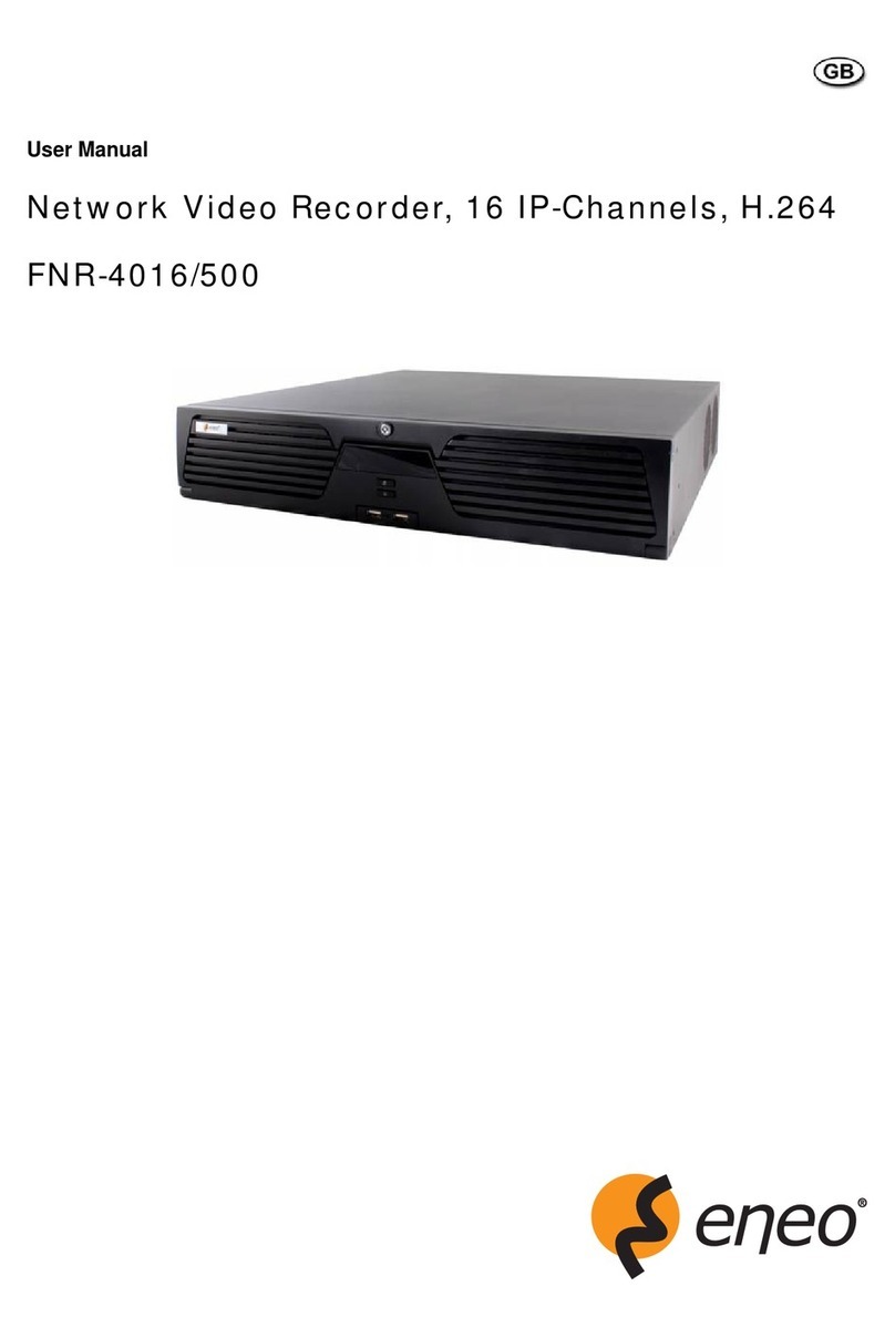
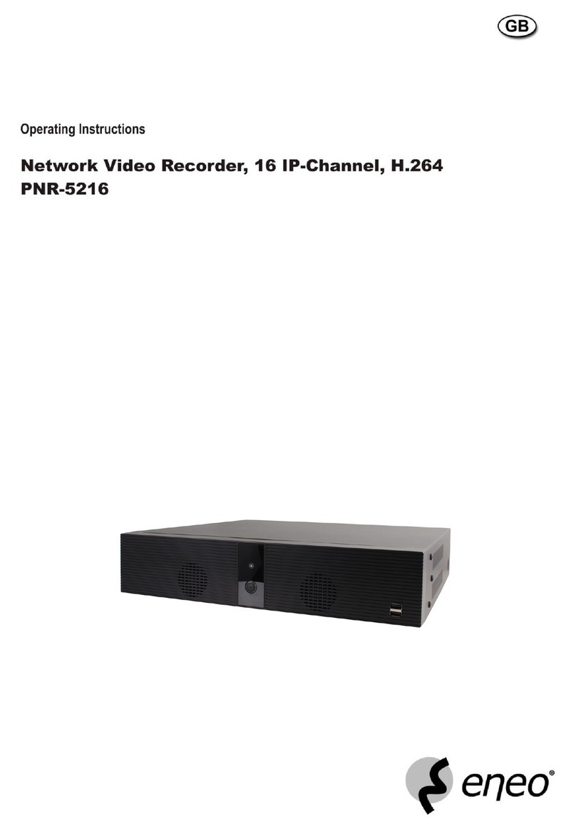
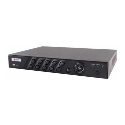
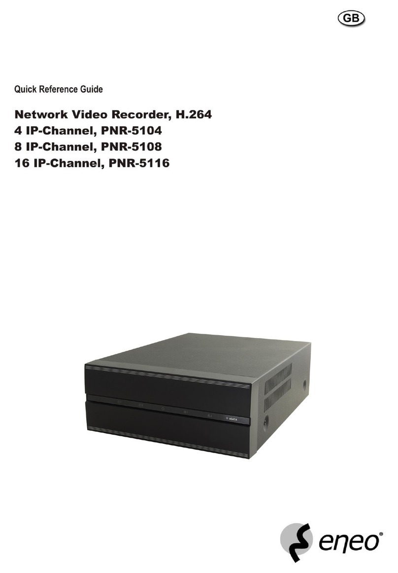
Eneo IER-28R080005A User manual

EN
Quick Installation Guide
Network Video Recorder, H.265,
HDMI, VGA, PoE, w/o HDD
IER-28R040005A
IER-28R080005A
IER-28R160005A
DE
FR
IT

2
Contents
Components...................................................................................................................5
Description ....................................................................................................................6
Front.......................................................................................................................................................................................6
Rear .......................................................................................................................................................................................6
Installation.....................................................................................................................8
Installation...........................................................................................................................................................................8
Installing HDD ...................................................................................................................................................................8
Starting System .................................................................................................................................................................9
Quick Setup ........................................................................................................................................................................9
Account ...........................................................................................................................................................................9
System .........................................................................................................................................................................10
Network ........................................................................................................................................................................11
Time/Date ................................................................................................................................................................... 12
Live Screen Conguration ......................................................................................... 13
Icons in Live screen ....................................................................................................................................................... 14
Live Launcher menu .................................................................................................................................................... 15
Quick menu ..................................................................................................................................................................... 16
Camera registration ..................................................................................................................................................17
Setup menu ................................................................................................................ 18
Further information .................................................................................................. 19

3
EN
Safety instructions
General safety instructions
• Before switching on and operating the system, rst read this safety advice and the operating instructions.
• Keep the operating instructions in a safe place for later use.
• Installation, commissioning and maintenance of the system may only be carried out by authorised
individuals and in accordance with the installation instructions - ensuring that all applicable standards and
guidelines are followed.
• Protect the devices from water penetration and humidity, since these can cause lasting damage.
• Should moisture nevertheless enter the system, under no circumstance switch on the devices under these
conditions, instead send them for examination to an authorised specialist workshop.
• The system must never be used outside of the technical specications, since this can destroy it.
• The device must be protected from excesses of heat, dust, humidity and vibration.
• When separating the system from the voltage supply, only ever use the plug to pull out the cable. Never
pull directly on the cable itself.
• Lay the connecting cables carefully and check that they are not mechanically stressed, kinked or damaged
and that no humidity can penetrate into them.
• In the event of a malfunction, please inform your supplier.
• Maintenance and repairs may only be carried out by authorised specialist personnel.
• The system must be isolated from the power supply before opening the housing.
• The device may only be opened by qualied service personnel. Unauthorised access invalidates any
warranty claim.
• Connection cables should always be exchanged through Videor E. Hartig GmbH.
• Use only original spare parts and accessories from Videor E. Hartig GmbH.
• The housing should only be cleaned using a mild domestic cleaning agent. Never use solvents or petrol as
these can permanently damage the surface.
• During installation, it is essential to ensure that the seals provided are correctly installed and that they are
not displaced during installation. Damaged seals must not be installed and will invalidate any warranty.
• The installer is responsible for the maintenance of the enclosure as per the technical data, e.g. by sealing
the cable outlets with silicone.
• Wire end ferrules should be used when shortening the exible connection cables.
• The devices may only be operated in the temperature range indicated in the data sheet and within the
dened air humidity range.
Product - Specic Safety Instructions
• The camera may never be pointed directly at the Sun with the aperture open (this will destroy the sensor).
• It is unavoidable that during manufacture and to a certain extent during later use, humidity will be present
in the ambient air within the device’s housing. In the event of large temperature uctuations, this humidity
may condense inside the housing.
• To avoid this condensation inside the very tightly sealed housing, the manufacturer has inserted silica gel
sachets in the housing of the various camera types.
• It is however a physical given, that these silica gel bags will reach saturation after a certain amount of time.
They should therefore be replaced with new silica gel sachets.
• During installation, it is essential to ensure that the seals provided are correctly installed and that they are
not displaced during installation. Damaged seals must not be installed and will invalidate any warranty.
• A multipolar, easily accessible isolation device should be installed in the proximity of the IR Spotlight, in
order to disconnect the device from the power supply for service work.
• The earth connection must be made according to the low impedance requirement of DIN VDE 0100.
• Subsequent painting of the equipment surface can impair the function.
• Any warranty claim is invalidated by subsequent painting.
• A safety margin of > 1m from the spotlight must be maintained when viewing directly into the IR Spotlight
in a darkened environment.
• Do not look directly at invisible LED radiation using optical instruments (e.g. a reading glass, magnifying
glass or microscope), since this can endanger the eyes, LED Class 1M.
• Operation of the IR spotlight with a defective cover or during repair is prohibited.
4
Class A device note
This is a Class A device. This device can cause malfunctions in the living area; in such an event, the operator may
need to take appropriate measures to compensate for these.
WEEE (Waste Electronical & Electronic Equipment)
Correct Disposal of This Product (Applicable in the European Union and other European countries with separate
collection systems).
This marking shown on the product or its literature, indicates that it should not be disposed with
other household wastes at the end of its working life. To prevent possible harm to the environment
or human health from uncontrolled waste disposal, please separate this from other types of wastes
and recycle it responsibly to promote the sustainable reuse of material resources. Household users
should contact either the retailer where they purchased this product, or their local government
oce, for details of where and how they can take this item for environmentally safe recycling.
Business users should contact their supplier and check the terms and conditions of the purchase
contract. This product should not be mixed with other commercial wastes for disposal.
Graphical symbols
Please pay attention to the safety instructions, and carefully read through this instruction guide before initial
operation.
Important points of warning are marked with a caution symbol.
iImportant points of advice are marked with a notice symbol.

5
EN
Components
This system comes with the following components;
• NVR
• Installation Guide
• CD
• DC adapter (4/8 ch) & power cord
• Mouse
• SATA cable
• SATA power cable
• HDD xing screw

6
Description
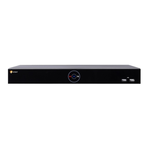
Front
No. Name Function
1Power status LED Pointing out device on/o.
2Recording status LED Pointing out recording in process.
3Network LED With a network viewer, pointing out network in connection.
4USB port USB port is connected for USB mouse or rmware upgrade, and data back-up.
Rear
4 channel model:

7
EN
8 channel model:
16 channel model:
No. Name Function
1IP CAM / PoE IP camera input port, IEEE802.3at PoE support.
2Network Network connector.
3Audio In Audio input port.
4Audio Out Audio output port.
5VGA VGA output port.
6HDMI HDMI output port.
7USB 3.0 USB 3.0 port is connected for data back-up.
8Alarm In/Out Alarm connector.
9RS485 RS-485 communication connector.
10 Power Switch Power On-O.
11 DC48V DC Adapter input port.
12 AC POWER INPUT AC Power cord input port.

8
Installation
Installation
This chapter describes the way to install NVR.
When installing a device, connect rear of the device with each port on the basis of below
connection map.
The device starts rst like below sequences:
1. Installing HDD
2. Connecting with an exterior device
3. Starting a system
4. Setting a quick setup
Installing HDD
How to install HDD in the device:
CAUTION:
• Withdraw the mains plug before installing HDD to reduce
the risk of injury or electrical shock, or device malfunction.
• Make sure to check the compatibility of HDD with the
device.
1. Always switch o and unplug the unit.
2. Unscrew with a screw driver (+) and open the unit cover.

9
EN
3. Install HDD in the bottom case.
4. Connect a data cable and power cable with HDD.
5. Close the cover and tighten screws.
Starting System
Power supply begins with system operation as follows:
1. Switching on initialize with below icons in order.
iNotice: Installing new HDD might take more initialize time.
2. With buzzer sounds, the start screen is presented.
3. In Log in screen, enter the ID, Password and press OK.
iNotice: Default ID & Password is admin/admin. For security reasons, please note in
the event the password is lost the device must be returned to our Service Centre so the
password can be reset.
CAUTION:
Please change password after login due to security.
Quick Setup
Account
Set ID and Password.

10
iNotice: Default ID & Password is admin/admin. Change password for security. Max
character length is 16.
System
How to set the system of Easy Installation:
Set each item in System setting screen.
• Language: Select system language.
• Device Name: Enter the device name.
• Keyboard ID: To identify device usages in controlling NVR with RS485 through a
keyboard

11
EN
• Selecting the device ID. In case of simultaneous use of equipment, set ID with
dierence.
• HD / VGA: Set resolution of a monitor connected to the device.
iNotice: When using many NVRs, set dierent IDs.
iNotice: Video is not displayed through VGA port if set 3840x2160 resolution. If reso-
lution is set to 3840x2160 and a monitor that does not support this resolution is connect-
ed to the HDMI port, it will automatically change to 1024x768 resolution.
Network
How to set the Network of Easy Installation:
Set each item in Network setting screen.
• WAN Port: Select whether to use static IP or dynamic IP.
• IP Address, Subnet Mask, Gateway, DNS, and Port: As for dynamic IP, enter informa-
tion in each space.

12
Time/Date
Set each item in Time/Date setting screen.
• Network Time Sync: Select network for synchronizing with time server.
• System Time: Not for synchronizing with network time server, set the device time;
otherwise (applying for Daylight saving time), select DST.
• Time Zone: Select time zone for the system being installed.
• DST Start/End: For applying Daylight saving time, set the application period.

13
EN
Live Screen Conguration
UI screen is congured like below gure.
No. Item Description
1 Setup menu Setting menu is located in the corner of upper screen.
2 Live screen Show live video of connected cameras.
3 Launcher menu Launcher menu is located in the corner of below screen.
4 Quick menu Clicking the right button of a mouse displays Quick menu.
5 Add to CH Move mouse cursor on the center of window to register IP camera manually. See ”Camera Registra-
tion”to display detailed information about the camera registration.

14
Icons in Live screen
Each icon in the live screen displays a present setting status or a function. UI screen con-
sists of like below.
iNotice: Chosen live screen is marked as a blue frame; mouse-located live screen is
marked as yellow one.
No. Icon Description
1 CH1 CAM1 Channel numbers and camera titles.
2A camera with PTZ function.
PTZ control function in process.
Recording in alarm event mode.
Recording in motion event mode.
Recording in panic recording mode.
Recording in consecutive recording mode.
3Video loss icon.
4Mic on/o.
5Speaker on/o.
6Displaying present time and date.

15
EN
Live Launcher menu
This chapter describes Launcher menu in the bottom of the screen.
No. Item Description
1Log in/out status and logged in ID.
2Date &Time Displaying present date and time.
3 HDD Displaying HDD capacity in use.
4Moving to previous/next partition screen.
5Displaying live screen in order set (toggle).
6Selecting partition mode to mark in live screen (single screen, 4-, 9-, and 16- partition).
7Stopping or replaying selected live screen images (toggle).
8Audio on or mute chosen live screen(toggle).
9 Instant recording for 10 seconds.
10 Make a backup video of users want.
11 Searching recording data (time, event, thumbnail, smart search, text andVCA).
12 Playback recorded data.
13 Starting immediate recording of selected channel.
14 Locking or releasing launcher menu (toggle).

16
Quick menu
This chapter depicts Quick menu when users click the right button of the mouse in live
screen.
No. Item Description
1 Screen Mode Selecting the partition mode of live screen (Full, 2X2, 3X3, and 4x4).
2 Fisheye Filter Selecting Fisheye lter. This menu is shown when sheye camera connected.
3 Zoom in Magnifying selected live screen (Zoom out, 2 times, 4 times, and 8 times).This menu is shown full screen mode
only.
4Freeze Freezes the video selected live screen images (toggle on / o).
5 Speaker Output/Mute Turning on/o a sound speaker.
6 PTZ Control Controlling PTZ function. This menu is shown when PTZ camera connected.
7 Stop Alarm Stopping monitoring alarm output and event.
8 Text Overlay POS text overlayed on the screen.This menu is show when enableText menu.
9 Playback Playing selected live screen images (before 30 sec, 1 min, 5 min, 10 min, 30 min, 1-hour, Go to last play time, and
Go to last record time).
10 Search Searching recording data (time, event, thumbnail, smart search, text andVCA).
11 Backup Backup video to USB drive.
12 Setup Opens the NVRs main set up menu.
13 Warp Monitor and control for remote recorder.
14 Camera Registration Opens a pop-up menu for IP camera registration.
15 Status Opens a pop-up menu showing: device system log, event, and recording status (system log, event, and record).
16 Log in/Log out Log in/Log out.
17 Shutdown Shuts down or restarts the device (shutdown, restart).

17
EN
Camera registration
Users can register the IP cameras.
No. Item Description
1Search the connected IP cameras.
2 Auto Assign Automatically assign the channel windows.
3Port Show the detected camera port (WAN, PoE).
4 Assign Selecting the channel windows manually.
5 Model Show detected camera model number.
6 IP Show detected camera IP address.
7 Status Show connection status.
8 Priority Select IP Address or Zero conf IP. When camera have IP address and zero conf IP, NVR display selected
priority address.
9 Add Manually Select channel and click to open manual add window.

18
Setup menu
This chapter describes Setup menu in the upper side of the screen.
iNotice: Setup screen is available to click Setup in Quick menu by clicking the right
button of the mouse.
No. Item Description
1 SYSTEM Setting the system environment.
2 CAMERA Setting the camera.
3 DEVICE Setting the non-camera devices connected to the NVR.
4 RECORD Setting the recording parameters.
5 EVENT Setting each event.
6 NETWORK Setting the network environment.
iNotice: For more details on each section within the Setup menu, please refer to the
main manual contained on the CD supplied with the NVR.

19
EN
Further information
iNotice: Please download the latest version of our new Management Software
eneo Center from the eneo website: www.eneo-security.com.
Make sure to always upgrade to the latest rmware version available from the eneo web-
site at www.eneo-security.com to receive the latest functionality for your product.
The manual, and other software tools are available on the eneo website at
www.eneo-security.com or on the included CD.
Information on compatible video management software solutions can be found in the
category Videomanagement at www.eneo-security.com.
Open Source Software
The software included in this product contains copyrighted software that is licensed
under open source licenses.
You may obtain the complete corresponding source code from eneo for a period of three
years after the last shipment of this product by sending email to:
If you want to obtain the complete corresponding source code with a physical medium
such as CD-ROM, the cost of physically performing source distribution might be charged.
For more details about Open Source Software, refer to the eneo website at
www.eneo-security.com or an included product CD.

20
Inhaltsverzeichnis
Komponenten ..............................................................................................................23
Beschreibung ..............................................................................................................24
Vorderseite........................................................................................................................................................................ 24
Rückseite .......................................................................................................................................................................... 24
Installation ...................................................................................................................26
Installation ........................................................................................................................................................................ 26
Einrichtung einer Festplatte ...................................................................................................................................... 26
Systemstart ...................................................................................................................................................................... 27
Schnellkonguration ................................................................................................................................................... 28
Konto ............................................................................................................................................................................ 28
System ......................................................................................................................................................................... 28
Netzwerk ..................................................................................................................................................................... 29
Zeit / Datum ............................................................................................................................................................... 31
Konguration der Live-Ansicht .................................................................................32
Symbole in der Live-Ansicht ...................................................................................................................................... 33
Live-Startprogrammmenü ......................................................................................................................................... 34
Schnellmenü ................................................................................................................................................................... 35
Kameraregistrierung ............................................................................................................................................... 36
Kongurationsmenü ..................................................................................................37
Weitere Informationen ...............................................................................................38
This manual suits for next models
5
Table of contents
Languages:
Other Eneo Network Hardware manuals

Eneo
Eneo PNR-5316 User manual

Eneo
Eneo PNR-5216 User manual

Eneo
Eneo IER-38R160005A User manual

Eneo
Eneo MAM-5MM2203M0A User manual

Eneo
Eneo FNR-4016/500 User manual

Eneo
Eneo IER-28R160005A User manual

Eneo
Eneo PSA-2400U User manual

Eneo
Eneo PNR-5316 User manual

Eneo
Eneo IER-25N080004A User manual

Eneo
Eneo PNR-5416 User manual
Popular Network Hardware manuals by other brands

HP
HP IBRIX X9720 System administrator guide

PCB Piezotronics
PCB Piezotronics 498A30 Installation and operating manual

Panasonic
Panasonic WJ-NXF02 operating instructions

3Com
3Com OfficeConnect Remote 510 user guide

Novus
Novus NVR-7308P8-H2 user manual

ZyXEL Communications
ZyXEL Communications PK5000Z How to configure