Planet POE-171A-60 User manual

802.3bt PoE++ Injector
POE-171A-60/POE-171A-95/POE-176-95
User's Manual

Table of Contents
1. Package Contents................................................................................. 3
2. Product Features .................................................................................. 4
3. ProductSpecications ........................................................................... 5
4. Product Outlook ................................................................................... 8
5. Hardware Installation.......................................................................... 12
5.1 Before Installation........................................................................ 12
5.2 POE-171A series/POE-176-95 Installation....................................... 12
6. Customer Support .............................................................................. 14

3
1. Package Contents
Thank you for purchasing PLANET POE-171A and POE-176-95 single-port
multi-Gigabit 802.3bt PoE++ Injector series and their brief product descriptions
are shown in the table below:
Model LAN Port Speed PoE Standard PoE Budget
POE-171A-60 10M/100M/1G/2.5G/5Gbps IEEE 802.3af/at/bt 60 watts
POE-171A-95 10M/100M/1G/2.5G/5Gbps IEEE 802.3af/at/bt 95 watts
POE-176-95 10M/100M/1G/2.5G/
5G/10Gbps IEEE 802.3af/at/bt 95 watts
Please unpack the box of the device carefully, and the box should contain the
following items:
z802.3bt PoE++ injector x 1
zQR code sheet x 1
zPower adaptor x 1
zAC power cord x 1
If any item is found missing or damaged, please contact your local reseller for
replacement.

4
2. Product Features
Interface
2 RJ45 interfaces
1-port Data + Power output
1-port Data input
1 DC 52~56V input power socket (POE-171A-60/POE-171A-95)
1 PoE mode (Standard/Legacy) DIP switch (POE-171A-60/POE-171A-95)
1 DC 52~54V input power socket (POE-176-95)
1 PoE mode (802.3bt/Legacy) DIP switch (POE-176-95)
Power over Ethernet
Complies with IEEE 802.3af/at/bt PoE end-span/mid-span PSE
Supports PoE power up to 60/95 watts for PoE port
Auto-detection of PoE IEEE 802.3af/at/bt equipment and devices from
being damaged by incorrect installation
Monitor the status of the total PoE usage in real time
Remote power feeding up to 100m
Auto-detection of DC input voltage

5
3.ProductSpecications
Product POE-171A-60 POE-171A-95 POE-176-95
HardwareSpecications
Interface
Input
Port
1 x RJ45 STP
Data In
Output
Port
1 x RJ45 STP
PoE (Data + Power) Out
DC
Socket 1 x 52~56V DC input socket 1 x 52~54V DC
input socket
Network Cable
Twisted-pair cable up to 100 meters (328ft)
10BASE-T: 4-pair UTP Cat. 3, 4, 5, 5e, 6, 6A
100BASE-TX: 4-pair UTP Cat. 5, 5e, 6, 6A
1G/2.5G: 4-pair UTP Cat 5e/Cat 6/Cat 6A/Cat 7
5G: 4-pair UTP Cat 6/Cat 6A/Cat 7
10G: 4-pair UTP Cat 6A/Cat 7 (POE-176-95 only)
LED Indicators
System: Power x 1 (Green)
PoE Port: PoE-in-Use x 1 (Amber)
Legacy Mode: Legacy x 1 (Amber)
PoE Usage: PoE Usage x 3 (Amber)
Data Rate 10M/100M/1G/2.5G/5Gbps 10M/100M/1G/
2.5G/5G/10Gbps
Dimensions
(W x D x H) 94 x 70.3 x 26.2 mm
Weight 192g 188g 192g
Unit Output Voltage DC 52~56V
Power
Requirements
DC 52-56V, 1.4A
max.
DC 52-56V, 2.5A
max.
DC 52-54V, 2.5A
max
Power Consumption 72 watts max. 130 watts max. 98 watts max.
No. of Devices that
can be powered 1

6
Power over Ethernet
PoE Standard IEEE 802.3af/at/bt PSE
PoE Power Output
Budget
DC 54V/30-watt
PoE via 2-pair
DC 54V/60-watt
PoE via 4-pair
DC 54V/30-watt
PoE via 2-pair
DC 54V/95-watt
PoE via 4-pair
DC 54V/30-watt
PoE via 2-pair
DC 54V/95-watt
PoE via 4-pair
PoE Power Output
Max. 60W for
1 m cable; max.
52W for 100 m
cable
Max. 89.5W for
1 m cable; max.
72W for 100 m
cable
Max. 80W for
1 m cable; max.
68W for 100 m
cable
PoE Power Supply
Type End-span + Mid-span
Power Pin
Assignment
Pair 1 End-span: 1/2 (-), 3/6 (+)
Pair 2 Mid-span: 4/5 (+), 7/8 (-)
PoE Mode
POE-171A-60/POE-171A-95/POE-176-95:
Standard: To provide power to the PD devices that
follow the IEEE 802.3af/at/bt standard.
Legacy: To provide power to the PD devices that
do not fully follow the IEEE 802.3af/at/bt standard.
Besides, the Legacy mode supports PoH and Ultra PoE.
Force: If the output power of injector is less than 1
watt when it works in Legacy mode; after 20 seconds,
the Force mode will be enabled.
When the Force mode is enabled, it will provide PD
with max. 60~95 watts.
If the output power of injector is less than 1 watt when
it works in Force mode; after 2 seconds, the Legacy
mode will be enabled.
Standards Conformance
Standards
Compliance
IEEE 802.3
10BASE-T
Ethernet
IEEE 802.3u
100BASE-TX Fast
Ethernet
IEEE 802.3
10BASE-T
Ethernet
IEEE 802.3u
100BASE-TX
Fast Ethernet
IEEE 802.3
10BASE-T
Ethernet
IEEE 802.3u
100BASE-TX
Fast Ethernet

7
Standards
Compliance
IEEE 802.3ab
1000BASE-T
Gigabit Ethernet
IEEE 802.3bz
2.5G/5GBASE-T
IEEE 802.3af
Power over
Ethernet
IEEE 802.3at
Power over
Ethernet Plus
IEEE 802.3bt
4-pair Power
over Ethernet
(Type 3)
IEEE 802.3ab
1000BASE-T
Gigabit Ethernet
IEEE 802.3bz
2.5G/5GBASE-T
IEEE 802.3af
Power over
Ethernet
IEEE 802.3at
Power over
Ethernet Plus
IEEE 802.3bt
4-pair Power
over Ethernet
(Type 4)
IEEE 802.3ab
1000BASE-T
Gigabit Ethernet
IEEE 802.3bz
2.5G/5GBASE-T
IEEE 802.3af
Power over
Ethernet
IEEE 802.3at
Power over
Ethernet Plus
IEEE 802.3bt
4-pair Power
over Ethernet
(Type 4)
Regulatory
Compliance FCC Part 15 Class A, CE
Environment
Operating
Temperature 0 ~ 50 degrees C
Storage
Temperature -10 ~ 70 degrees C
Operating Humidity 5 ~ 90%, relative humidity, non-condensing
Storage Humidity 5 ~ 90%, relative humidity, non-condensing
1. As the IEEE 802.3bt device provides high power, please use
high-quality network cable and RJ45 connector.
2. The maximum PoE output power depends on the cable length,
the quality of cable, and DC input voltage.
3. Please power on the device after changing the DIP switch
mode.

8
4. Product Outlook
Standard Legacy
PoE Mode
Ethernet+DC
10/100/1G/2.5G/5G
60W+
40W
20W
PoE Usage
PWR
PoE-in-Use
Legacy
POE-171A-60
802.3bt PoE++ Injector
Ethernet
10/100/1G/2.5G/5G
52-56V , 2.5A max.
IEEE 802.3bt Power over Ethernet Injector
Figure 1: POE-171A-60 Outlook
Standard Legacy
PoE Mode
Ethernet+DC
10/100/1G/2.5G/5G
90W+
60W
30W
PoE Usage
PWR
PoE-in-Use
Legacy
IEEE 802.3bt Power over Ethernet Injector
POE-171A-95
802.3bt PoE++ Injector
Ethernet
10/100/1G/2.5G/5G
52-56V , 2.5A max.
Figure 2: POE-171A-95 Outlook

9
802.3bt Legacy
PoE Mode
PWR
PoE-in-Use
Legacy
IEEE 802.3bt Power over Ethernet Injector
Ethernet+DC
10/100/1G/2.5G/5G/10G
90W+
60W
30W
PoE Usage
POE-176-95
802.3bt PoE++ Injector
Ethernet
10/100/1G/2.5G/5G/10G
52-54V , 2.5A max.
Figure 3: POE-176-95 Outlook
LED Indicators:
LED Color Function
PWR Green Lights to indicate the 802.3bt PoE++ injector has
power.
PoE-in-Use Amber Lights to indicate the device is providing PoE power.
Legacy Amber Lights to indicate the device is working in Legacy
mode.
PoE Usage Amber PoE Usage LED can monitor the DC input voltage or
the status of the power usage.
Detection of DC input voltage of POE-171A series and POE-176-95:
When user powers on the POE-171A injector via the DC adapter, the injector
willdetecttheDCinputvoltageandthenPoEUsageLEDwillashthreetimes.
LED Description
20W/30W Flashing three times means the DC input voltage is 48~51V.
40W/60W Flashing three times means the DC input voltage is 52~54V.
60W+/90W+ Flashing three times means the DC input voltage is 55~56V.

10
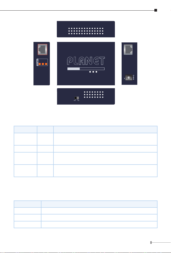
Monitoring of power usage of POE-171A-60:
LED Description
20W
1.OtoindicatethePoEusageislessthan9W.
2. Blinks to indicate that the PoE usage is around 10W to 19W.
3. Lights to indicate the PoE usage is more than 20W.
40W 1. Blinks to indicate that the PoE usage is around 30W to 39W.
2. Lights to indicate the PoE usage is more than 40W.
60W+ 1. Blinks to indicate that the PoE usage is around 50W to 59W.
2. Lights to indicate the PoE usage is at its maximum.
Monitoring of power usage of POE-171A-95 and POE-176-95:
LED Description
30W
1.OtoindicatethePoEusageislessthan14W.
2. Blinks to indicate that the PoE usage is around 15W to 29W.
3. Lights to indicate the PoE usage is more than 30W.
60W 1. Blinks to indicate that the PoE usage is around 45W to 59W.
2. Lights to indicate the PoE usage is more than 60W.
90W+ 1. Blinks to indicate that the PoE usage is around 75W to 89W.
2. Lights to indicate the PoE usage is at its maximum.
PoE Mode:
PoE Mode Description
Standard/
802.3bt Fully conforms to the IEEE 802.3af/at/bt standard.
Legacy
The legacy detection is to identify the valid current signature of
the PDs that do not fully follow the IEEE 802.3af/at/bt standard.
This protects against damage to the PDs as the right PoE mode
is applied.
The PoE++ Injector also supports Force Power Mode in the
Legacy mode. If the output power of the PoE++ Injector in
the Legacy Mode is less than 1 watt for 20 seconds, the Force
Mode will be enabled for 2 seconds. If the loading is still less
than 1 watt, the Legacy Mode will be enabled again.

11
The POE-171A series and POE-176-95 in the Force Mode
will also provide a maximum power to the PD. TO PREVENT
THE DEVICES FROM DAMAGE, please make sure the remote
devices supports either the Legacy or Force Mode before turning
the DIP switch to the Legacy Mode.
1. For safety, power off the device first before adjusting the DIP
switch setting. After the adjustment, turn back on the device.
2. Before connecting the Ethernet+DC port to network device,
please make sure that it accepts PoE input to prevent
damage.

12
5. Hardware Installation
The following section describes the hardware installation of the POE-171A
series and POE-176-95. Before connecting any network device to it, please
read this chapter carefully.
5.1 Before Installation
Before your installation, it is recommended to check your network
environment. If there is any IEEE 802.3bt device that needs to be powered
on and works normally, the POE-171A series/POE-176-95 provides you with
a way out to supply power to this Ethernet device conveniently and easily.
The POE-171A series/POE-176-95 is equipped with a power adaptor which is
100-240V AC input, and can inject DC 52~56V (POE-171A-Series) and DC
52~54V (POE-176-95) power into the pin of the twisted-pair cable (pair 1/2
[-], 3/6 [+] and pair 4/5 [+], 7/8 [-]).
5.2 POE-171A series/POE-176-95 Installation
1. Connect the AC power adaptor to the “52-5xV DC IN” of the POE-171A
series/POE-176-95; the “PWR” LED will be steadily on.
2. Connect a standard Ethernet cable from an Ethernet switch or PC worksta-
tion to the “Ethernet” port of the POE-171A series/POE-176-95
3. Connect the long cable to the “Ethernet+DC” port of the POE-171A series/
POE-176-95 and the IEEE 802.3af/at/bt PD.

13
4. The POE-171A series/POE-176-95, adopting the IEEE 802.3af/at/bt tech-
nology, can directly connect with any IEEE 802.3af/at/bt end-nodes, such
as PTZ (pan, tilt & zoom) network cameras, PTZ speed dome cameras, color
touch screen, Voice over IP (VoIP) telephones and multi-channel wireless
LAN access points as the screen in Figure 3 is shown below.
10G/5G/2.5G/1G/100Mbps Data Rate
AC-to-DC Adapter
110-240V AC
PoE+ IP Camera
PoE+ Wireless AP
5-speed Multi-Gigabit Ethernet Switch
RJ45 UTP Cable
Power
Data
Power
Data
Powered Devices
802.3bt PoE++ Splitter
802.3bt PoE++ Injector
PWR
PoE-in-Use
Legacy
Power over Ethernet Injector
Figure 3: Architecture of Connected IEEE 802.3af/at/bt Devices
Once the POE-171A series/POE-176-95 detects the existence of an IEEE 802.3af/at/bt
device, the PoE-in-Use LED indicator will be steadily on to show it is providing power.
1. The 10Gbps speed is available for the POE 176-95 only.
2. Since the PoE ports of the POE-171A series (52-56V DC) and
POE-176-95 (52-54V DC) support different DC PoE power
output, check whether the PD accepts the DC power range.
Otherwise, it will damage the PD.

14
6. Customer Support
Thank you for purchasing PLANET products. You can browse our online FAQ resource at
the PLANET Web site rst to check if it could solve your issue. If you need more support
information, please contact PLANET support team.
PLANET online FAQs:
http://www.planet.com.tw/en/support/faq.php
Support team mail address:
Copyright © PLANET Technology Corp. 2023.
Contents are subject to revision without prior notice.
PLANET is a registered trademark of PLANET Technology Corp.
All other trademarks belong to their respective owners.

15
FCC Warning
This device has been tested and found to comply with the limits for a Class
A digital device, pursuant to Part 15 of the FCC Rules. These limits are
designed to provide reasonable protection against harmful interference when
the equipment is operated in a commercial environment. This equipment
generates, uses, and can radiate radio frequency energy and, if not installed
and used in accordance with the Instruction manual, may cause harmful
interference to radio communications. Operation of this equipment in a
residential area is likely to cause harmful interference in which case the user
will be required to correct the interference at his own expense.
CE Mark Warning
This device is compliant with Class A of CISPR 32. In a residential environment
this equipment may cause radio interference.
WEEE Warning
To avoid the potential eects on the environment and human health
as a result of the presence of hazardous substances in electrical and
electronic equipment, end users of electrical and electronic
equipment should understand the meaning of the crossed-out
wheeled bin symbol. Do not dispose of WEEE as unsorted municipal waste and
have to collect such WEEE separately.
Other manuals for POE-171A-60
1
This manual suits for next models
2
Table of contents
Other Planet Laboratory Equipment manuals
Popular Laboratory Equipment manuals by other brands

IKA
IKA ULTRA -TURRAX Tube Drive operating instructions

Radleys
Radleys Reactor-Ready Lab Reactor instructions

Miele professional
Miele professional PG 8583 operating instructions

Sigma
Sigma 3-16L operating manual

Light Progress
Light Progress UV-DIRECT E40H-K-NX quick start guide

Labconco
Labconco FreeZone 6 user manual