manuals.online logo
Brands
  1. Home
  2. •
  3. Brands
  4. •
  5. Planika
  6. •
  7. Burner
  8. •
  9. Planika FKE-0683 Instruction sheet

Planika FKE-0683 Instruction sheet

www.planikafires.com i0776#01 30.04.2014 1
Configuration of the module with Wi-Fi and Smart Home System manual
This manual allows to configure the module in order to control the bio fireplace b means of:
1. The device that has access to Wi-Fi (smartphone, tablet) – THE CONFIGURATION OF Wi-Fi
and SMARTPHONE . . . . . . . . . . . . . . . . . . . . . . . . . . . . . . . . . . . . . . . . . . . . . . . . . . . . . . . 1
2. Smart Home S stem – SMART HOME SYSTEM CONNECTION . . . . . . . . . . . . . . . . . . . . 5
1. THE CONFIGURATION OF WiFi and SMARTPHONE
The configured appliance will allow to:
-Turn on the product (if READY message on displa )
-Turn off the product (for COOLING THE DEVICE or READY message on displa )
-Make the flame size lower or higher while the bio fireplace is working
-Turn on/turn off ‘Lock the device’ function (Customer’s Menu, point 1)
-Choose the bio fireplace which is to be controlled.
It will be also possible to check the serial number, program version, website version and total operating
time.
FLA 3 communicates with the exterior appliances b means of Wi-Fi.
Make sure that Wi-Fi network ou have is of 802.11 b/g/n standard and it operates the encr ption of
WPA/WPA2 PSK.
If our Wi-Fi network does not fulfill the above mentioned requirements it has to be adjusted.
Otherwise, remote controlling of the bio fireplace via the appliance will not be possible.
If Wi-Fi network is read , prepare the formatted USB flash drive.
Create a text file on USB flash drive with the name ‘wifi’ and ‘txt’ extension.
Save the name of the network and password in the file in a given format, where:
Instead of ‘Wi-Fi Network name’ – enter the name of the network, e.g. ‘home’
Wi-Fi Network Password – password to the network, e.g. ‘m net’
Example:
www.planikafires.com i0776#01 30.04.2014 2
Make sure that the bio fireplace is disconnected from the mains then put USB flash drive to USB port
on the side part of the product.
Connect the bio fireplace to the mains and wait min. 5 minutes. USB flash drive ma be disconnected
and the product ma be turned on with button.
Hold ‘+’ for 8 seconds and ‘Customer’s menu’ will appear [p. 10 in User’s manual]. Press ‘+’ to go to
point 4 ‘Device IP’ and confirm b pressing ‘-‘.
Product’s IP needed for the operation via the configured appliance will be visible then. Correct IP
format is: 192.168.XXX.XXX .
It ma happen that the displa ed IP is incorrect. In such case follow the instructions below.
0.0.0.1
No communication with the module
at all
It is normal during the
initialization of the
product. If it does not disappear after several
minutes after turning on the bio fireplace,
begin to format USB flash drive again.
0.0.0.2
No connection with the network
(wrong data / IP is bus / no network)
Follow the procedure of giving the network
parameters once more – install USB flash
drive again.
0.0.0.3
Text mode
–
jumper was not
downloaded
Follow the procedure of giving the network
parameters once more – install USB flash
drive again. Call SERVICE.
127.0.0.1
No connection with the network
(wrong data / IP is bus / no network)
Follow the
procedure of giving the network
parameters once more – install USB flash
drive again.
WARNING! There is possibilit to check the reason of configuration failure. To do this read the file
‘wifi.txt’.
Network parameters changed
The change of all the net
work parameters was successful
Error 0x01
Interfaces error (call service)
USB
www.planikafires.com i0776#01 30.04.2014 3
Data changed successfull
The change of network password or
network
name was
successful
Incorrect data format
Data
incorrectl entered
into the file (save data again on
USB
flash drive, if it does not work, format USB flash drive or use a
different one)
If the displa ed IP number is correct one, save it.
The mobile appliance should be connected to the configured Wi-Fi network. The operation of bio
fireplace via website was tested with the following browsers:
Windows: Opera, Firefox, Chrome, IE min 11
Android: Firefox, Chrome, Opera Browser, Opera Classic, Safari
Apple - Safari, Chrome
In the address bar enter the saved IP address and download the webpage.
The displa will appear on the appliance:
Due to SETTINGS function it is possible to determine:
-Serial number
-Displa and microprocessor’s program version
Allows to give an
name of the appliance
to facilitate choosing it
from the list of
different appliances.
Activates ‘Lock the
device’ function (see:
User’s manual -> III
Customer’s menu -> 1.
www.planikafires.com i0776#01 30.04.2014 4
-total time of the product operation
-website version
Thanks to MANAGE function it is possible to control unlimited number of configured bio fireplaces.
If Wi-Fi network has access to the Internet, it is possible to enter www.planikafires.com or
www.fireline.planikafires.com/fla
WARNING!
To control the bio fireplace, it needs to be installed according to the Installation Manual. The user has
to be familiar with the User’s Manual. Onl after the configuration it is permitted to turn on the product
for the first time.
www.planikafires.com i0776#01 30.04.2014 5
2. SMART HOME SYSTEM CONNECTION
When Smart Home S stem driver installed it is possible to control the bio fireplace when it comes to:
-Turning on the product (if READY message on displa )
-Turning off the product (if COOLING THE DEVICE or READY message on displa )
-Making the flame size lower or higher while the bio fireplace is working
It is possible to see the current mode of the product on the Smart Home S stem control panel:
-read to start (message READY)
-working (message WORKING)
-lack of fuel (message NO FUEL)
-waiting for an occurrence (message WAITING or COOLING THE DEVICE)
-ERROR XX.
The description of Smart Home S stem ports
Description of electrical connectors
GND – COM DC -V
STA T – 12 DC +V input initializing the bio fireplace, signal as an impulse lasting 100ms up to 1s
STOP – 12 DC +V input turning off the bio fireplace, signal as an impulse lasting 100ms up to 1s
UP – 12 DC +V input increasing the flame, signal as an impulse lasting 100ms up to 1s
DOWN – 12 DC +V input decreasing the flame, signal as an impulse lasting 100ms up to 1s
A – EADY – transmitter output signaling that the device is read
information
control
GND COM DC
-
V
START
STOP
UP
DOWN
INPUT
12-24
VDC
A
B
C
D
www.planikafires.com i0776#01 30.04.2014 6
B – WO KING - transmitter output signaling that the device is working
C – FUEL – transmitter output signaling lack of fuel
D – E O – transmitter output signaling error / other
A+B – transmitter output
All the ports have been adjusted to work within the voltage of 12V – 24V of the direct current. Higher
voltage requires the use of additional limiter installed on the module’s port.
There is possibilit to control a few bio fireplaces simultaneousl . In order to do so, it is essential to
divide the signal into several ones, one per each product.
Scheme
Description:
Input – voltage port 12V – 24V of the direct current.
OUTPUT - voltage port 12V – 24V of the direct current depending on the mode of the bio fireplace.
Chart with the signals that ma occur depending on the bio fireplace mode.
1 – port where the signal is
0 – lack of the signal in the port
A
B
C
D
READY
1
0
0
0
WORKING
0
1
0
0
FUEL
0
0
1
0
ERROR
0
0
0
1
WAIT/COOLING
1
1
0
0
www.planikafires.com i0776#01 30.04.2014 7
Mode of operation
After connecting according to the scheme above, controlling of the bio fireplace takes place via
emitting single and short electrical impulses (lasting from 100ms to 1s) to the electrical connectors. A
single impulse directed to START port leads to turning on the bio fireplace (when stand-b mode is
activated manuall with button).
A single impulse directed to STOP port leads to switching the bio fireplace into stand-b mode.
A single impulse directed to UP port increases flame size b one level.
A single impulse directed to DOWN port decreases flame size b one level.
Electrical connector READY indicates that the bio fireplace is read to start.
Electrical connector WORKING indicates that the bio fireplace is working. Disappearance of the signal
is equal to turning off the product or lack of fuel.
Electrical connector FUEL indicates lack of fuel.
Electrical connector ERROR indicates an errors of the product (in order to identif what happened
one needs to have a look at the fireplace displa ).
Electrical connector READY + WORKING indicates initialization or cooling of the bio fireplace.
Disappearance of this signal is equal to switching into READY mode or other mode visible on the
displa .

Other Planika Burner manuals

Planika ZEN Garden User manual

Planika

Planika ZEN Garden User manual

Planika KL21 Square User manual

Planika

Planika KL21 Square User manual

Planika Simple User manual

Planika

Planika Simple User manual

Planika Forma 1200 Front User manual

Planika

Planika Forma 1200 Front User manual
Planika Totem User manual

Planika

Planika Totem User manual

Planika Jar User manual

Planika

Planika Jar User manual

Planika Hot Box REMOTE User manual

Planika

Planika Hot Box REMOTE User manual

Planika FLA 2 E 4 User manual

Planika

Planika FLA 2 E 4 User manual

Planika Dancing Flames User manual

Planika

Planika Dancing Flames User manual

Planika Prime Fire 590 User manual

Planika

Planika Prime Fire 590 User manual

Planika Cabo User manual

Planika

Planika Cabo User manual

Planika KL21 Rio User manual

Planika

Planika KL21 Rio User manual

Planika Senso User manual

Planika

Planika Senso User manual

Planika Pure Flame User manual

Planika

Planika Pure Flame User manual
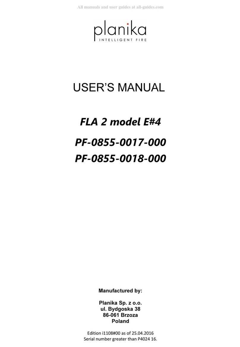
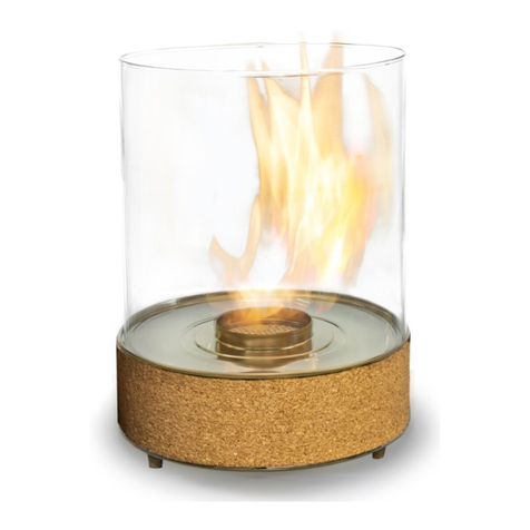
Planika Chantico User manual

Planika

Planika Chantico User manual
Popular Burner manuals by other brands

Megatherm Nani 35 Installation & user manual

Megatherm

Megatherm Nani 35 Installation & user manual

Weil-McLain F10 - F20 Specifications

Weil-McLain

Weil-McLain F10 - F20 Specifications

Riello GI/EMME 1400 Installation, use and maintenance instructions

Riello

Riello GI/EMME 1400 Installation, use and maintenance instructions

COMPANION RB20 instruction manual

COMPANION

COMPANION RB20 instruction manual

Riello Burners RS Series Installation, use and maintenance instructions

Riello Burners

Riello Burners RS Series Installation, use and maintenance instructions

Riello 40 FS20 One stage operation

Riello

Riello 40 FS20 One stage operation

Riello GS10 Installation, use and maintenance instructions
Riello

Riello GS10 Installation, use and maintenance instructions
Campmaster CM1089R Assembly and operating instructions

Campmaster

Campmaster CM1089R Assembly and operating instructions

Ecoflam MAXFLAM D 10 manual

Ecoflam

Ecoflam MAXFLAM D 10 manual

Coyote C1PB Use & care manual

Coyote

Coyote C1PB Use & care manual

baltur BTL 4P instructions

baltur

baltur BTL 4P instructions

Beckett AFG Oil Burner 240V Product sheet

Beckett

Beckett AFG Oil Burner 240V Product sheet

baltur COMIST 122 N instructions

baltur

baltur COMIST 122 N instructions

Coyote C1PB install guide

Coyote

Coyote C1PB install guide

Jetboil LUNA Series Instructions for use

Jetboil

Jetboil LUNA Series Instructions for use

Riello RX 1500 S/E Installation, use and maintenance instructions
Riello

Riello RX 1500 S/E Installation, use and maintenance instructions
Riello 809 T80 Installation, use and maintenance instructions
Riello

Riello 809 T80 Installation, use and maintenance instructions

Bentone B30A2.2H Installation and maintenance  instruction

Bentone

Bentone B30A2.2H Installation and maintenance instruction

manuals.online logo
manuals.online logoBrands
  • About & Mission
  • Contact us
  • Privacy Policy
  • Terms and Conditions

Copyright 2025 Manuals.Online. All Rights Reserved.