GF Signet 9950 User manual

The 9950 is a multi-channel, multi-sensor transmitter designed to meet and exceed the
industry standards, and expectations for a small, compact, ¼” DIN transmitter. The power
and versatility of the 9950 allows the use of up to six GF sensors to manage complex water
treatment applications.
The 9950 analyzer supports all like sensors or a mix of any GF sensors. Sensor types and
accessories supported by the 9950 are GF Flow (frequency and/or digital S³L), pH/ORP,
Conductivity/Resistivity, Salinity, Temperature, Pressure, Level, Dissolved Oxygen and any
device that transmits a 4 to 20 mA signal when used with the single channel
3-8058 iGo® Signal Converter.
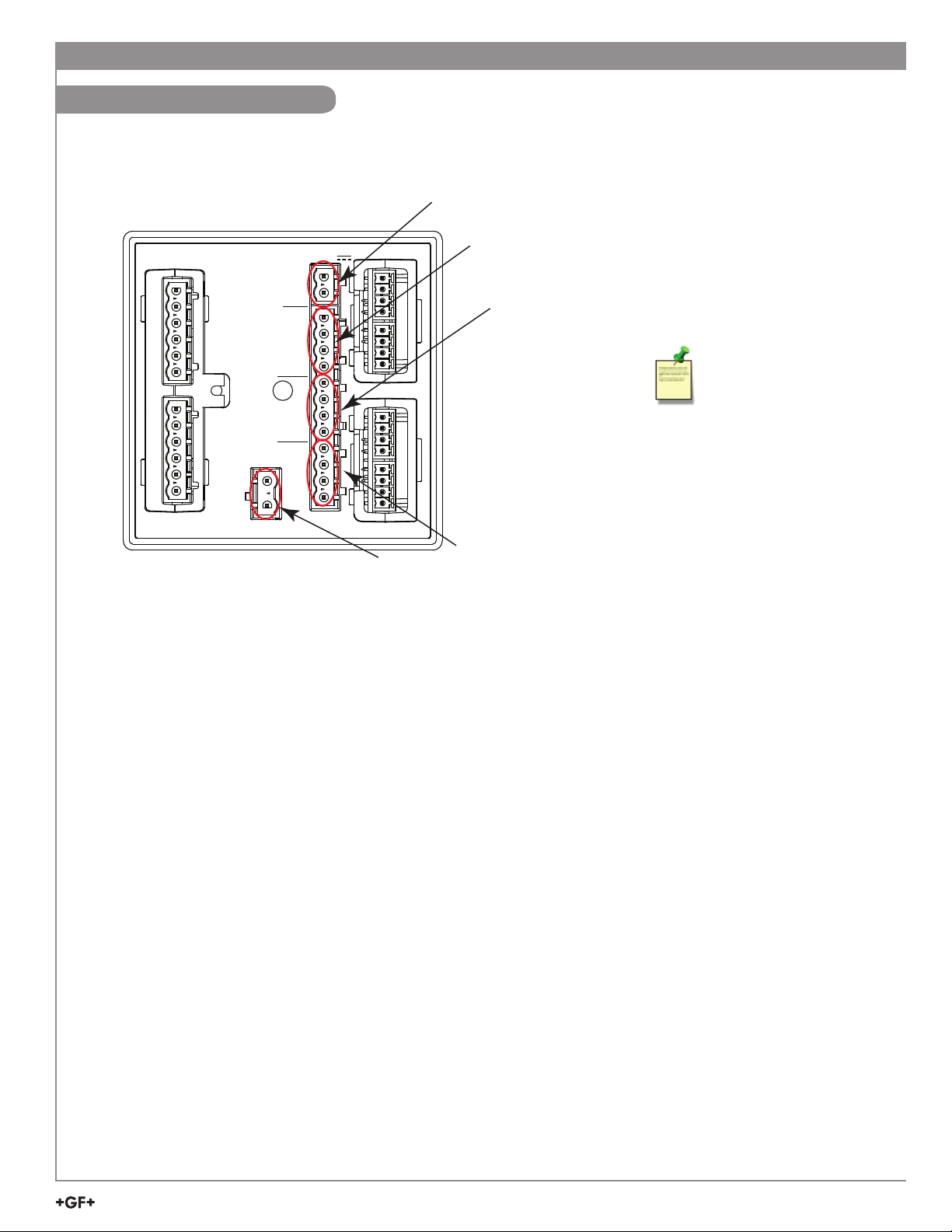
The 9950 base unit comes complete with two each 4 to 20 mA output, two additional dual 4
to 20 mA output modules can be installed to increase the number of 4 to 20 mA outputs to a
total of six outputs.
Four Conductivity sensor measurements are supported with either a single or dual channel
conductivity module. If six conductivity sensors are required, the use of a 3-2850-51-XX
can be added to the main S³L input terminals.
The 3-9950.393-3 Relay Module provides four binary inputs that are compatible with any
open collector or mechanical contacts, such as level switches, flow switches, pressure
switches or other devices. The 9950 offers advanced features such as derived functions,
advanced multiple relay modes (Boolean logic) and timer-based relay functions.
The 9950 Modbus Module allows for remote access to primary and secondary
measurements, derived functions, status of current loop outputs and relays, over a serial
RS485 Modbus automation network.
The 9950 supports the following modules:
• Four Channel Mechanical Relay Module
• Two Mechanical and Two Solid State
Relay Module
• Two Mechanical Relays and Four Binary
Inputs Module
• Single Channel Conductivity
Resistivity Module
• Dual Channel Conductivity Module
• Dual Channel 4 to 20 mA Current Loop
Output Module
• Modbus Module
*3-9950-10.090*
GF 9950 Six-Channel Transmitter
3-9950-10.090 Rev. 1 01/23
3-9950-10, -11
Operating Instructions (Refer to pg. 11)
Description
Compatibility
The 9950 is compatible with all GF products
listed in the column to the right.
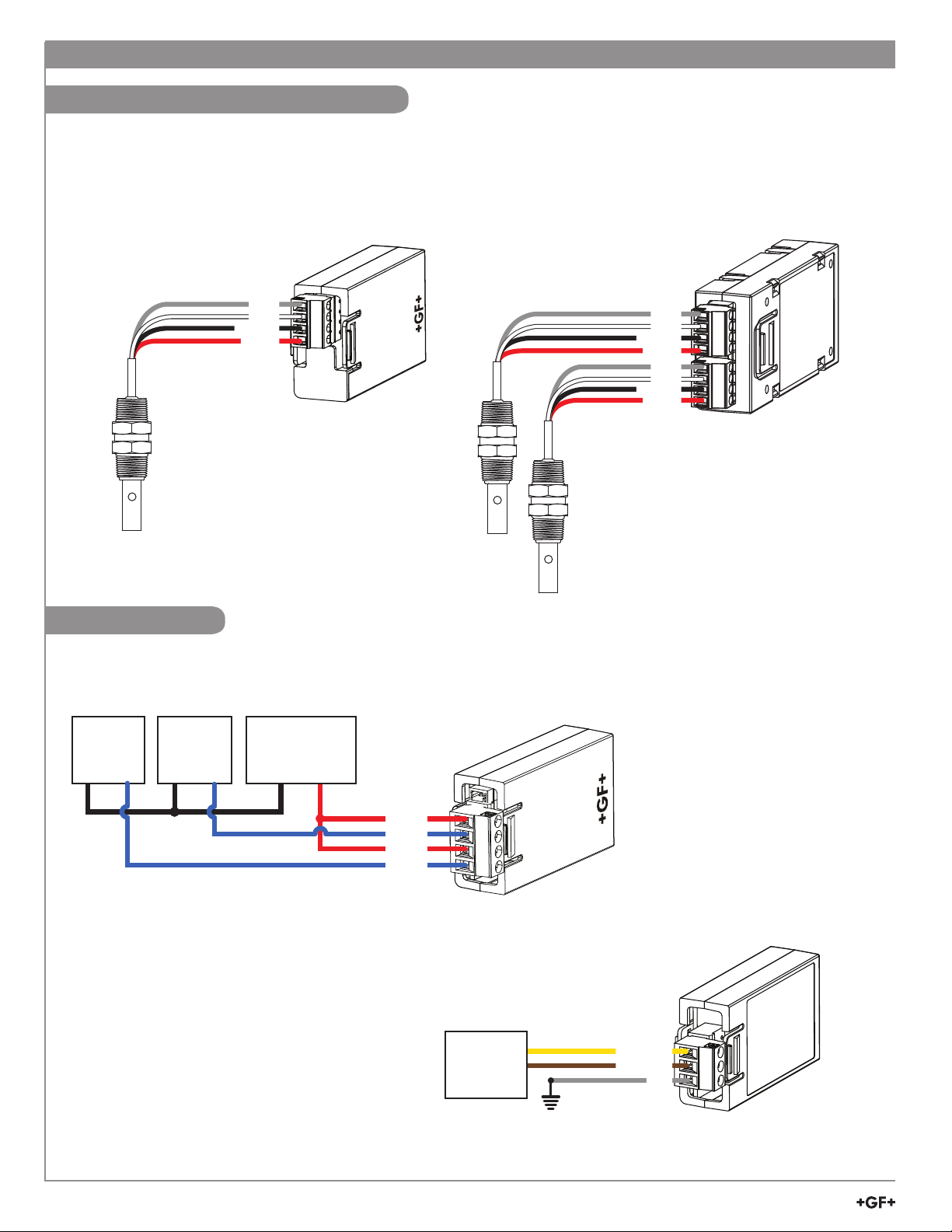
• pH/ORP electrodes require the GF 2751
DryLoc® Sensor Electronics
(sold separately).
• Conductivity/Resistivity measurement
requires the GF 2850 Conductivity/Resistivity
electronics or a single or dual conductivity
module and proper conductivity sensor
(sold separately).
English
Sensor
Model
Freq
Output
Digital (S3L)
Output
Requires
8058-1
515 X
525 X
2000 X
2100 X
2250 X
2350 X
2450 X
2507 X
2536 X
2537-5 X
2540 X
2551 XX
2552 XX
258X XX
U1000 XX
U3000 XX
U4000 XX
2260 X
2270 X
2290 X
2291 X
2610-51 X
2751 X
2850-51-XX* X
2850-61* X
2850-63* X
• English
* No conductivity module required
E171559
CUS

2GF 9950-10 Six Channel Transmitter
Warning / Caution / Danger
Indicates a potential hazard. Failure to follow all warnings
may lead to equipment damage, injury, or death
Electrostatic Discharge (ESD) / Electrocution Danger
Alerts user to risk of potential damage to product by ESD
Electrocution Danger
Alerts user to risk of potential of injury or death via
electrocution
Personal Protective Equipment (PPE)
Always utilize the most appropriate PPE during installation
and service of GF products
NOTE / Technical Notes
Highlights additional information or detailed procedure
• Please read entire manual before unpacking, setting up or
operating this equipment. Adhere to all danger, warning and
caution statements. Failure to do so could result in serious
injury to the operator or damage the equipment. Make sure the
protection provided by this equipment is not impaired, do not use
or install this equipment in any manner other than specified in
this manual.
• This unit is designed to be connected to equipment which can
be hazardous to persons and property if used incorrectly.
• Read and understand all associated equipment manuals and
safety warnings before using with this product.
• Remove power to unit before wiring connections.
• Wiring connections to this product should only be performed by
qualified personnel.
• Do not use unit if front panel is cracked or broken.
Safety Information
Start-Up Guide
Panel Cutout
92 x 92 mm
(+ 0.8, - 0 mm)
3.6 x 3.6 in.
(+0.031, -0 in.)
Panel Cutout
92 x 92 mm
(+ 0.8, - 0 mm)
3.6 x 3.6 in.
(+0.031, -0 in.)
Panel Cutout
92 x 92 mm
(+ 0.8, - 0 mm)
3.6 x 3.6 in.
(+0.031, -0 in.)
Panel Cutout
92 x 92 mm
(+ 0.8, - 0 mm)
3.6 x 3.6 in.
(+0.031, -0 in.)
minimum
clearance
25 mm
(1 in.)
For future reference, for each installation, it is recommended to record the part number and serial number of each of the
components listed here:
Facility Tag Number or System ID (user assigned):__________________
_
Base unit 3-9950-____ S/N ___________________
Relay Module 3-9950.393-____ S/N ___________________
Single Channel Cond./Resist. Module 3-9950.394-____ S/N ___________________
Dual Channel 4-20 Current Loop Out. Module 3-9950.398-____ S/N ___________________
Dual Channel Conductivity Module 3-9950.394-2 S/N ___________________
Modbus Module 3-9950.395-M S/N ___________________
Installation
Panel Mount Installation
panel
V+
FREQ
DATA
GND
V+
FREQ
DATA
GND
Loop1+
Loop1–
Loop2+
Loop2–
PWR+
PWR–
CH2 CH1
USB
RELAY MODULE
MODULE 1
MODULE 2
Made in U.S. from U.S. and imported parts
DC POWER
12-32 VDC
0.50A Max
DC Power
12-32 VDC
0.03A Max
Loop Voltage
N
L
100-240 VAC~
50-60 Hz, 24VAMax
quick-clip
gasket on
front side
of panel
mounting
bracket
Allowable panel thickness 2.36 mm (0.093 in.) to 33 mm (1.31 in.)
Before commissioning the device, make sure the supply voltage matches the voltage specifications on the nameplate.
For DC power input and Loop current regulated voltage, use UL60950-1 or UL61010-1 certified power supply.
Power supply shall also be rated for operation at 4000 m altitude. Provide a suitable switch or circuit breaker the installation.
This switch must be located close to the device (easily reached), and marked as a circuit breaker. The switch or circuit breaker to be
used for power disconnect shall be certified to IEC 60947-1 and IEC 60947-3, per IEC 61010-1, Clause 6.11.4.2.
Overcurrent protection (rated > 10 A) is required for the power cable.

3
GF 9950-10 Six Channel Transmitter
The 9950 requires regulated
12 to 32 VDC, ±10% regulated
(24 VDC nominal) or 100-
240 VAC at 50-60 Hz from an
external power supply
(not supplied).
Maximum current draw is:
500 mA with DC power
24 VA with AC power
Terminal Identification
Start-Up Guide
Prepare the transmitter installation location. If the back of the transmitter is difficult to access when
installed, wire the removable terminal blocks first, then install it completely.
+V
FREQ
DATA
GND
+V
FREQ
DATA
GND
Loop 1+
Loop 1–
Loop 2+
Loop 2–
PWR+
PWR–
CH2 CH1
USB
RELAY MODULE
MODULE 1
MODULE 2
Made in U.S. from U.S. and imported parts
N
L
100-240 VAC~
11-24 VDC
DC Power Terminals
Current Loop Outputs 1 and 2
Sensor Input 1
(Frequency/S3L)
AC Power Terminals
Sensor Input 2
(Frequency/S3L)
DC Power Terminal 3-9950-10 or 3-9950-11
Required by the instrument
• 12 to 32 VDC, ±10% regulated, 0.5 A MAX. DC power input and Loop current regulated voltage require the use of a
UL60950-1 or UL61010-1 certified power supply. Power supply shall also be rated for operation at 4000 m altitude.
AC Power Terminal 3-9950-11 Only
Required by the instrument
• 100-240 VAC at 50-60 Hz, 24 VA MAX
Relay Module
Dependent on model
• 3-9950.393-1 Four mechanical relays rated at 5A, 250 VAC or 5A, 30 VDC
• 3-9950.393-2 Two mechanical relays, 5A 250 VAC or 30 VDC, and two solid state relays rated at 50 mA, 30 VAC or 30 VDC
• 3-9950.393-3 Two mechanical relays, 5A 250 VAC or 30 VDC, and four binary inputs rated at 6 mA, 10 VDC to 24 VDC
Modules 1 and 2
• 3-9950.394-1 Single Channel Direct Conductivity/Resistivity Module
• 3-9950.394-2 Dual channel Conductivity Module
• 3-9950.395-M Modbus Module
• 3-9950.398-2 Dual Channel 4 to 20 mA Current Loop Output Module
Sensor 1 and Sensor 2: Digital (S3L)/Frequency Input
• V+: +5 VDC out to sensor (black wire)
• FREQ: Frequency input signal from sensor (red wire)
• S3L DATA: Digital input signal from sensor (red wire)
• GND: Sensor ground (white wire or silver wire from paddle wheel flow sensor)
Loop Outputs
• Two Passive 4 to 20 mA current loop outputs 12 - 32 VDC, ±10% regulated (30 mA Max)
• Up to 4 additional Loop Outputs via the Dual Channel 4 to 20 mA Output Module
ModBus Module
• Six Channel Primary and Secondary values

4GF 9950-10 Six Channel Transmitter
Sensor Wiring
Start-Up Guide
Loop
+V
FREQ
+V
FREQ
DATA
GND
Loop
CH2 CH1
+V
FREQ
DATA
GND
DC POWER
Loop
+V
FREQ
+V
FREQ
DATA
GND
Loop
CH2 CH1
+V
FREQ
DATA
GND
DC POWER
Loop
+V
FREQ
+V
FREQ
DATA
GND
Loop
CH2 CH1
+V
FREQ
DATA
GND
DC POWER
FLOW
FLOW
515/8510
525 2536/8512 2540
2000 2100 2507
Black
Red
White
9950 Frequency
X
No connection
Black
Red
White
2537-5
S1 S2
Blk Red Shld -+
9950 S3L Inputs
X
No connection
* 2551-XX-21, -41
Display Magmeter
2250 2350 2450
2551* 2751 2850 Black
Red
White
9950 S3L Inputs
X
No connection
Shield
Blue
Green
Brown
No
connection
9950 S3L Inputs
+V
FREQ
DATA
GND
+V
FREQ
DATA
GND
Loop1+
Loop1–
Loop2+
Loop2–
PWR+
PWR–
CH2 CH1
DC POWER
+V
FREQ
DATA
GND
Black
White
Shield
PWR +
PWR –
3-2610-51
+
–
Power Supply
12 to 32 VDC
Technical Notes:
• Wiring terminals on the 2537 are rated for 16 to 22
AWG wires.
• The cable must be 7 mm to 10 mm in diameter
(0.275 in. to 0.394 in.) to seal properly in the
liquid-tight connector.
• The conduit ports have ½ inch NPT threads.
After routing the cables, seal the port with a liquid-tight
conduit connector (3-9000.392-1) or with conduit.
• The 2537 models connect to the 9950 via the
Digital (S3L) output.
Technical Notes:
• See corresponding product manuals for maximum
cable length.
• Maintain cable shield through cable splice.
• Route sensor cable away from AC power lines.
• Select "Yes" to CH # Flow 515/525 when setting up
the input on the 9950. On the 515/8510 and 525
installations, connect the silver (shield) wire to earth
ground in case of EMI noise interference.
Technical Notes:
• Sensor dependent, see sensor manual for maximum
cable length.
• Maintain cable shield through cable splice.
• Route sensor cable away from AC power lines.
• Connect the silver (shield) wire to earth ground in case
of EMI noise interference.
• The 9950 is not compatible with the 3-2580-63, dual
channel conductivity device.
NOTE: The 2850 has no SHIELD wire.
Technical Notes:
The wiring of the 3-2610-51 is non-standard:
• RED is 12 to 24 VDC (PWR +)
• WHITE is Data
• BLACK is VDC Ground (PWR -)
• A jumper MUST be installed between PWR- and
S3L GND.
WARNING: When using more than one DO sensor it is
recommended to:
1. Not to use daisy chain wiring
2. Wire directly to CH1 or CH2 sensor input terminals
3. Share the loads across both input channels
NOTE: 3-2610-51 only.
Sensor Terminal Connections
Sensor
Terminal 2551 2751 2850
1+V Shield +V
2S3L/Freq GND S3L
3GND S3L GND
4Not Used +V Not Used

5
GF 9950-10 Six Channel Transmitter
2551-XX-11
Blind Magmeter
Black
Red
9950 S3L Inputs
+V
FREQ
DATA
GND
+V
FREQ
DATA
GND
Loop1+
Loop1–
Loop2+
Loop2–
PWR+
PWR–
CH2 CH1
DC POWER
+V
FREQ
DATA
GND
X
No connection
White
Shield
Black
Red
White
9950 Frequency
+V
FREQ
DATA
GND
+V
FREQ
DATA
GND
Loop1+
Loop1–
Loop2+
Loop2–
PWR+
PWR–
CH2 CH1
DC POWER
+V
FREQ
DATA
GND
X
No connection
Shield
3
4
Frequency
S L
3
3
4
Input Wiring for 2551 and 2552 sensors
• Either Frequency or Digital (S3L) may be used.
• GF recommends configuring these sensors with the Digital (S3L) output to display
reverse flow (negative numbers).
• Input type is selected by choosing between “SENSOR FREQ” and "SENSOR S3L" in
the FLOW sensor type INPUT menu (Refer to page 11).
Frequency Output Technical
Notes (2551 & 2552):
• The frequency output will
be displayed as positive
flow regardless of the
flow direction.
• 5 VDC power required by
the 2551 & 2552 is supplied
by the 9950. No additional
power is required.
• Connect the silver wire
(shield) to earth ground
in case of EMI noise
interference.
2552 Technical Notes:
• The 2552 outputs an open
collector frequency signal that
can be connected to the 9950.
• Route sensor cable away
from AC power lines.
• Connect the silver (shield)
wire to earth ground in case
of EMI noise interference.
2551 Technical Notes:
• When the blue jumper
illustrated here is
placed over both pins,
the 2551-XX-11 (Blind
Magmeter) outputs an
open collector frequency
signal. When the jumper
is removed (or placed
over one pin for storage)
the 2551-XX-11 outputs a
digital (S3L)
signal (recommended).
Sensor Wiring
Start-Up Guide
Only in case of EMI interference.
Refer to Frequency Output Technical Notes (2551 & 2552) at right.
2552
Black
Brown
White
9950 S3L Inputs
+V
FREQ
DATA
GND
+V
FREQ
DATA
GND
Loop1+
Loop1–
Loop2+
Loop2–
PWR+
PWR–
CH2 CH1
DC POWER
+V
FREQ
DATA
GND
Black
Brown
White
9950 Frequency
+V
FREQ
DATA
GND
+V
FREQ
DATA
GND
Loop1+
Loop1–
Loop2+
Loop2–
PWR+
PWR–
CH2 CH1
DC POWER
X
No
connection
+V
FREQ
DATA
GND
Blue
Blue
X
No connection
Shield
Shield
Sensor
Terminal Signal
1Black (+V)
2Red (S3L/Freq)
3White (GND)
4Not Used

6GF 9950-10 Six Channel Transmitter
Sensor Wiring
Start-Up Guide
2581 Black
Red
Shield (EMC enhancement)
24 VDC @ 1A min.
Power Supply
–
+
Power cable
+V
FREQ
DATA
GND
9950
Digital (S3L)
+V
FREQ
DATA
GND
+V
FREQ
DATA
GND
Loop1+
Loop1–
Loop2+
Loop2–
PWR+
PWR–
CH2 CH1
DC POWER
+V
FREQ
DATA
GND
X
No connection
X
No connection
9950
Frequency
+V
FREQ
DATA
GND
+V
FREQ
DATA
GND
Loop1+
Loop1–
Loop2+
Loop2–
PWR+
PWR–
CH2 CH1
DC POWER
X
No connection
X
No connection
2581
Output cable
Black
Brown
Shield
Blue not used
Not used
Ground (White)
Data (Red)
2581
Output cable
Black
Brown
Shield
Blue not used
Not used
Ground (White)
Frequency (Red)

7
GF 9950-10 Six Channel Transmitter
Power Wiring
Start-Up Guide
+V
FREQ
DATA
GND
+V
FREQ
DATA
GND
PWR+
PWR–
CH2 CH1
DC POWER
DC power optional
Loop1+
Loop1–
Loop2+
Loop2–
Made in U.S. from U.S. and imported par
N
L
100-240 VAC~
50-60 Hz, 24VA Max
Neutral
Line
100-240 AC
+
–
Black
Red Power Supply
12 to 32VDC
+
–
Red
Black
PLC or Recorder
Loop Input
4 to 20 mA
+
–
PLC or Recorder
Loop Input
4 to 20 mA
Red
Black
3-9950-10
3-9950-11
WARNING
DO NOT connect AC power to the DC version
THE 3-9950-10 MUST BE POWERED BY
12 - 32 VDC at 0.5 A.
+V
FREQ
DATA
GND
+V
FREQ
DATA
GND
Loop1+
Loop1–
Loop2+
Loop2–
PWR+
PWR–
CH2 CH1
DC POWER
and imported par
+
–
Black
Red Power Supply
12 to 32 VDC
+
–
Red
Black
PLC or Recorder
Loop Input
4 to 20 mA
+
–
PLC or Recorder
Loop Input
4 to 20 mA
Red
Black
Caution:
Electrical shock hazard exists!
Never connect live AC lines to the instrument.
External DC Power is
required for the current
loops.
CAUTION
Keep AC power separate from
sensor and signal wiring to prevent
interference and damage to the
9950 Transmitter.
Caution:
For DC power input and loop current regulated
voltage, use UL60950-1 or UL61010-1 certified
power supply. Power supply shall also be rated
for operation at 4000 m altitude.

8GF 9950-10 Six Channel Transmitter
Start-Up Guide
Relay Module Wiring
3-9950.393-1 and 3-9950.393-2
Relay 1: The alarm is OFF during normal operation, and will
go ON when relay energizes according to 9950
Relay settings.
Relay 4: The valve is ON during normal operation, and will
go OFF when relay energizes according to 9950
Relay settings.
NO = normally open (closes when energized)
NC = normally closed (opens when energized)
Mechanical Relays Rating: 5A 250 VAC, 5A 30 VDC
Solid State Relays Rating: 50 mA 30V AC/DC
(for 309950.393-2 relay 1 & 2)
3-9950.393-3
The alarm is OFF during normal operation, and will go ON when the
relay energizes according to 9950 Relay settings.
Binary input 4 will be ON when the tank level is above the level
switch, Binary Input 4 will be OFF when the tank level is below the
level switch.
Binary Input Ratings
Maximum Input voltage
(without damage) 30 VDC
Minimum Input voltage
(without damage)
-5 VDC
(no operation below 0 VDC)
Maximum input voltage for
signal “Off” (low or "0") 1.5 VDC
Minimum input voltage
for signal “On” (high or "1") 3.0 VDC
Maximum current draw for
signal “0” (low) <500 ADC
Minimum current draw
for signal “1” (high) 500 A
Typical current draw
for signal “1” (high) 6.0 mA at 30 VDC, 4.8 mA at 24 VDC,
2.4 mA at 12 VDC, 1.0 mA at 5 VDC
• Terminals accept 12 to 22 AWG wire.
• Strip 10 to 12 mm (0.4 to 0.5 in.) of insulation from wire tips and tin bare ends to eliminate fraying.
• Insert wire tip or ferrule completely into the terminal and secure with the screw.
• Do not allow any AC leads that may be connected to the internal relays to come in contact with low voltage wiring.
NO 1
N/C 1
COM 1
NO 2
N/C 2
COM 2
RELAY 1
RELAY 2
RELAY 3
RELAY 4
NO 3
N/C 3
COM 3
NO 4
N/C 4
COM 4
AC or DC
power
Valve
Flow
AC or DC
power
ALARM!
3-9950.393-1
N/O 1
N/C 1
COM 1
SW4
SW COM
N/O 2
N/C 2
COM 2
SW3
SW2
SW1
X
RELAY 1
RELAY 2
BINARY INPUT 3
BINARY INPUT 1
No Connection
BINARY INPUT 2
BINARY INPUT 4
AC or DC
power
ALARM!
Level
Level Switch
9950.393 Internal Power
N/O 1
N/C 1
COM 1
SW4
SW COM
N/O 2
N/C 2
COM 2
SW3
SW2
SW1
X
RELAY 1
RELAY 2
BINARY INPUT 3
BINARY INPUT 1
No Connection
BINARY INPUT 2
BINARY INPUT 4
AC or DC
power
ALARM!
Level
Level Switch
DC power +
-
9950.393 External Power
3-9950.393-3 Internal Power
3-9950.393-3 External Power
If an externally powered sensor is connected with the
3-9950.393-3 module, set the power switch to the EXT
position. The module can power external sensors by
switching the power switch to the INT position. Maximum
power that can be drawn from the module is 6mA at 30 VDC.
INT
EXT
Power
Switch
EXT
INT

9
GF 9950-10 Six Channel Transmitter
Start-Up Guide
Relay Module Wiring
8059 External Relay Module
3-8059-4AC Four external dry-contact relays with power supply
3-8059-4 Four external dry-contact relays
3-8050.396 RC Filter Kit
6205-0002 DIN Rail, 1m
6205-0003 End Clips, DIN Rail
• The 9950-10/11 will support up to eight (8) relays, though only four actually fit directly inside its compact ¼ DIN enclosure.
8059 External Relay Modules of four relays may be connected to the 9950 via digital (S³L) at the I/O Module (this does NOT-
consume a sensor input channel).
• External relays are completely independent of internal relays, so it is not necessary to install an internal relay module into the
9950 to use the external relays. In the 9950 menus, external relays will always be identified as Relays A, B, C, and D.
• Digital (S³L) pass-thru terminals on the 8059 can help to reduce sensor wiring congestion at the 9950.
See the 8059 instruction manual for details.
• External Relays mount on DIN rail inside a panel and can be tested remotely from the 9950, or locally with switches built-in for
convenience. They also include LED relay status indicators, but the status of these and all relays is available at all times in a
single screen in the 9950 View mode.
• Any and all relays are freely assignable to any channel. Hysteresis and time delay are adjustable for each relay.
• It is perfectly acceptable to mix and match relay types between internal and external modules.
However, NOTE: The 9950 only allows external relays to be used in modes Off, Low, Hi, Window, Total, and Error.
• 8059 External Relay Modules contain dry-contact relays only. These electromechanical switches are suitable for many general-
purpose applications, AC or DC, including AC loads up to 250 V.
• Switching active loads (most commonly inductive) can cause contact arcing sufficient to damage relays. The RC Filter Kit or
“snubber” is available as an accessory to reduce or eliminate these damaging effects.
NC C NO
RELAY A
NC C NO
RELAY B
NC C NO
RELAY C
NC C NO
RELAY D
+
S
3
L
- +
S
3
L
-
OUTPUT 24VDC
+ -
AC INPUT
INPUT PASS-THRU
L N
COM
32:(5
Signet 3-8059 Relay Module Test A
Test B
Test C
Test D
Relay A
Relay B
Relay C
Relay D
LISTED
E171559
®
NC COM NO
RELAY A
NC COM NO
RELAY B
NC COM NO
RELAY C
NC COM NO
RELAY D
DC OUTPUT
+ -
DC INPUT
- +
+
S
3
L
- +
S
3
L
-
INPUT PASS-THRU
COM
32:(5
Signet 3-8059 Relay Module Test A
Test B
Test C
Test D
Relay A
Relay B
Relay C
Relay D
LISTED
E171559
®
8059-4AC8059-4
NC C NO
RELAY A
NC C NO
RELAY B
NC C NO
RELAY C
NC C NO
RELAY D
+
S3L
- +
S3L
-
OUTPUT 24VDC
+ -
AC INPUT
INPUT PASS-THRU
L N
COM
POWER
Signet 3-8059 Relay Module Test A
Test B
Test C
Test D
Relay A
Relay B
Relay C
Relay D
LISTED
E171559
®
9950 S3L Inputs
+V
FREQ
DATA
GND
+V
FREQ
DATA
GND
Loop1+
Loop1–
Loop2+
Loop2–
PWR+
PWR–
CH2 CH1
DC POWER
+V
FREQ
DATA
GND
Shield
PWR +
PWR –
AC or DC
Power
8059-4AC
S³L Connector
{
DC
{
AC
{
NOTE: 9950-1 and 9950-2 do not support the 8059 external relay.

10 GF 9950-10 Six Channel Transmitter
Start-Up Guide
Conductivity Module Wiring
Loop Wiring
3-9950.394-1
Single Channel Cond.
SHIELD (silver)
TEMP (white)
ISO GND (black)
SIGNAL (red)
Shield
Black
White
Red ISO GND
TEMP
SHLD
SIGNAL
3-9950.394-1
Single Channel
Conductivity Module
3-9950.394-2
Dual Channel
Conductivity Module
Shield
Black
White
Red ISO GND
TEMP
SHLD
SIGNAL
Shield
Black
White
Red ISO GND
TEMP
SHLD
SIGNAL
PLC
or
Recorder
–+
PLC
or
Recorder
–+
3-9950.398-2
Dual Channel 4-20mA
Loop A +
Loop A -
Loop B +
Loop B -
Power
Supply
–+
Loop B+
Loop A–
Loop B–
Loop A+
3-9950.398-2
Dual Channel
4 to 20 mA Module
3-9950.395-M
Modbus Module
(Optional) Shield
Brown
Yellow
Shield recomended in
noisy environment
RS485
RCVR
PLC
–
+
GND
D0 + RS485
D1 + RS485

11
GF 9950-10 Six Channel Transmitter
Keypad Functions
The four buttons of the keypad (ENTER) are used to navigate display modes according to the descriptions in this table.
Notice the function of each button may change depending on the display mode.
System Setup Menu
Start-Up Guide
ENTER
4
DATE FORMAT
100% SOLUTION
NAME
SAVING
24 HOUR
AM/PM
GERMAN
LANGUAGE
LANGUAGE
00:00:040
AM/PM
09:11:04
MM/DD/YYYY
DD/MM/YYYY
YYYY/MM/DD
LANGUAGE
LANGUAGE
02/25/20162
AM/PM
02/25/2016
99.999
99,999
OR
ENTER
saves
changes
ENTER
METRIC
U.S. CUSTOMARY
LOOKING FOR
TEXT 3
SENSOR TYPE
MM/DD/YYYY
YYYY/MM/DD
DD/MM/YYYY
NONE
FLOW
pH
ORP
FACTORY
ENTER
saves
changes
TIME FORMAT
TEXT 3
24 HOUR
SET TIME
TEXT 3
08:56:47
DATE FORMAT
TEXT 3
MM/DD/YYYY
SET DATE
TEXT 3
07/04/2022
SET DECIMAL MARK
TEXT 3
999.99
SELECT UNITS
TEXT 3
US CUSTOMARY
SETUP
3
CHANNEL 1
PRESS ENTER
SETUP
CHANNEL 2
PRESS ENTER
ENGLISH
DEUTCH
ESPAÑOL
FRANÇ
SETUP
CHANNEL 3
SETUP
CHANNEL 4
SETUP
CHANNEL 5
SETUP
CHANNEL 6
EXIT STARTUP
COND/RES
NONE
S3L 2209292345
MOD1A
MOD1B
S3L 2209291234
ENTER
saves
changes
FREQ1
FREQ1
This menu operation sets up the 9950 for basic function when
initially powered up or when the 9950 has ALL six channels set to
FACTORY.
1. Select desired language using the and arrows.
Press ENTER to save.
2. Press to select the TIME FORMAT.
Press or to select 24 hour or AM/PM.
Press ENTER to save the format selection.
3. Press the move to the next selection, SET TIME.
Press to scroll through hours, and minutes place values.
Use or to adjust the value.
Press ENTER to save the time selection.
4. Press to move to the next selection, SET DATE FORMAT.
Press to select the MM/DD/YYYY date format and or to
scroll through other format options.
Press ENTER to save the date format selection.
5. Press to move to the next selection, SET DATE.
Press to scroll through the days, months, and years.
Use or to adjust the number, and to select the next
number.
Press ENTER to save the Date selection.
6. Press to move to the next selection,
SET DECIMAL MARK.
Press and use or to highlight desired decimal separator
(comma or decimal mark).
Press ENTER to save the decimal mark selection.
7. Press to move to the next selection, SELECT UNITS.
Press and scroll or to choose Metric or
U.S. Customary.
Press ENTER save unit selection.
8. Press to move to the next selection SETUP CHANNEL
Press ENTER.
Use or to scroll through the sensor list and select another
sensor type to assign to the channel.
Press ENTER to save sensor type selected.
Press to bypass channel 1 and scroll to any specific channel
(1-6) for set up.
NOTE: If no sensor is selected, it is recommended to select
NONE as sensor choice.
Press to move to CHANNEL SOURCE.
Use or to scroll through the list of available sensors or
modules for the channel TYPE selected in step 8.
Press ENTER to save sensor source selected.
Repeat steps in number 8 to set up channels 2 through 6.
When done, press +together one time exits to the
previous menu.
Press +together a second time to exit Easy Start Up.

12 GF 9950-10 Six Channel Transmitter
Password
Password Overview
The password is required to start editing. Once entered correctly, this password will not be needed for subsequent uses, until the
menu system is exited. The password will be required when the menu system is re-entered.
Your choice of password (STD or CODE) is selected in the Options Mode.
STD
The standard (STD) password is , pressed in sequence. This password is designed to protect the 9950 from
unintentional changes. It is best suited for systems where a group of people need to be able to change settings.
CODE
The CODE default setting is 0000, adjustable to any 4-digit numerical code up to 9999. Using a personal code provides the
maximum degree of security. This code can be modified in the Options mode.
ENTER
UP, DOWN keys
Scroll through Menu options or adjust values during editing
Press both together to exit a menu or escape without saving
RIGHT key
Select item or character to edit
ENTER key
Access menus
Save changes
Operation
ENTER
4
00.00 99.99
00.00 99.99
CH5
9999.9
9999.9
9999.9
9999.9
CH6
UOM
UOM
UOM
UOM
Relay 1
Indicator LED
Relay 2
Indicator LED
Backlight Sensor
(do not block)
Bar Graph
Channel 1,3,5
display area
Menu Navigation Keys
Relay 3
Indicator LED
Relay 4
Indicator LED
Units of Measure
(GPM, pH, sec, %, etc.)
Numeric
Values
or labels
Bar Graph
Channel 2,4,6
display area
Numeric
Values
or labels Units of Measure
(GPM, pH, sec, %, etc.)
Start-Up Guide

13
GF 9950-10 Six Channel Transmitter
Refer to your local Georg Fischer Sales office for the
most current warranty statement.
All warranty and non-warranty repairs being returned
must include a fully completed Service Form and
goods must be returned to your local GF Sales office or
distributor.
Product returned without a Service Form may not be
warranty replaced or repaired.
GF products with limited shelf-life (e.g. pH, ORP,
chlorine electrodes, calibration solutions; e.g. pH buffers,
turbidity standards or other solutions) are warranted out
of box but not warranted against any damage, due to
process or application failures (e.g. high temperature,
chemical poisoning, dry-out) or mishandling (e.g. broken
glass, damaged membrane, freezing and/or extreme
temperatures).
Warranty Information
Table of Contents
Description .......................................................................1
Compatibility.....................................................................1
Safety Information............................................................2
Installation ........................................................................2
Terminal Identification ......................................................3
Wiring ......................................................................... 4-10
Sensor Wiring......................................................... 4-6
Power Wiring..............................................................7
Modules Wiring .................................................... 8-10
System Setup Menu.......................................................11
Password .......................................................................12
Keypad Operation ..........................................................12
Warranty Information......................................................13
Dimensions ....................................................................14
Module Installation .........................................................14
Plug-In Modules .............................................................15
Relay Modules ...............................................................15
Conductivity Loop and Modbus Modules ......................16
Signal Type: Frequency ................................................16
Signal Type: Digital (S3L) .............................................16
Signal Type: 4 to 20 mA................................................17
Relay Functions .............................................................17
Relay Modes ............................................................ 17-19
Derived Functions ..........................................................20
Sensor-Specific Menus............................................ 21-50
Flow.................................................................... 21-22
pH....................................................................... 23-25
ORP.................................................................... 26-27
Conductivity/Resistivity ...................................... 28-29
Pressure............................................................. 30-31
Level/Volume...................................................... 31-34
Temperature ....................................................... 34-35
4 to 20 mA.......................................................... 36-37
Salinity................................................................ 38-40
Dissolved Oxygen .............................................. 41-42
Relay Menus ............................................................ 43-57
Low..........................................................................43
High .........................................................................44
Window IN or Window OUT....................................45
Proportional Pulse...................................................46
Pulse Width Modulation ..........................................47
Volumetric Pulse .....................................................48
Total Pulse...............................................................49
United States Pharmacopeia ..................................50
Error Mode ..............................................................51
Binary Input .............................................................52
Timer ................................................................. 53-55
Multiple.............................................................. 56-57
Menu System .................................................................58
Common Menus....................................................... 59-64
Loop Menus .............................................................59
Option Menu........................................................ 60-63
View Mode ...............................................................64
Troubleshooting ....................................................... 65-66
Averaging .......................................................................67
LOG Current Loop Output .............................................67
Custom Measurements............................................ 68-71
Calibration Procedures - pH .................................... 72-73
Calibration Procedure - ORP ................................... 74-75
Calibration Procedure - Conductivity/Resistivity............76
Calibration Procedure - Salinity .....................................77
Calibration Procedure - Flow .........................................78
Calibration Error Messages ...........................................79
USP Limits......................................................................80
Modbus .........................................................................80
Modbus Communication Setting Menus........................81
Maintenance...................................................................81
Specifications ........................................................... 82-83
Ordering Information ......................................................84

14 GF 9950-10 Six Channel Transmitter
3-9950-10/-11
The plug-in modules may be installed either before or after the
base unit is mounted. If the 9950 Base Unit will be mounted
using the provided quick clip mounting bracket, install plug-in
modules first with power disconnected.
To install modules:
Remove power from the 9950. Carefully align pins and
connectors (do not bend connecting pins) and push module firmly
into place, then attach with screw(s) for Relay Modules only.
CAUTION
Exercise care when installing modules.
Do not bend connecting pins.
To move modules:
Remove power from the 9950.
For Relay Modules:
Unplug connectors, remove screw(s), and carefully pull
module straight out from the base unit. Do not bend the
connecting pins.
For Conductivity, Dual Channel 4 to 20 mA, and Modbus
Modules:
Unplug connectors and squeeze the two retaining tabs while
pulling module out of 9950.
WARNING
Relays may be connected to external
high-voltage power sources or multiple power
sources creating an electrocution hazard.
Dimensions
Module Installation
99.06 mm
(3.90 in.)
12 34
99.06 mm
(3.90 in.)
ENTER
90.73 mm
(3.57 in.)
91.44 mm
(3.60 in.)
102.37 mm
(4.03 in.)
82.60 mm
(3.25 in.)
Side ViewFront View
CAUTION
Avoid Electrostatic Discharge (ESD).
MODULE 1
MODULE 2
Rounded
Corners
Dual Channel
4 to 20 mA Module
Shown with Single Channel
Conductivit
y
Module installed in Module Slot 2
Important!
Ensure the rounded
corner of the module is
alligned with the rounded
corner of the module slot
before installing
9950
Note: Modules can be installed in either slot.

15
GF 9950-10 Six Channel Transmitter
•
Minimize handling of the plug-in modules to reduce the possibility of damage due to ESD.
•
Handle modules by the edges.
Never touch any exposed circuitry or contacts.
•
Wear an anti-static wristband or stand on an anti-static mat, or keep one hand touching a
properly grounded pipe or other piece of properly grounded metal when handling modules.
CAUTION
Avoid Electrostatic Discharge (ESD).
Optional modules and accessories are available for the 9950:
a. Optional Relay Module
b. Optional Module 1
c. Optional Module 2
Each item is ordered separately. Modules are field-replaceable at any time.
Refer to Module Installation (page 8) and Ordering Information (page 82) for more details.
NOTE:
• The four red Indicator LEDs on the front panel of the 9950 show the status of relays
1, 2, 3, & 4. The LEDs will activate with or without a relay module installed.
• Hysteresis and time delay are adjustable for each relay.
Mfr. Part No. Code Description
3-9950.393-1 159 310 268 Relay Module - 4 Mechanical Relays
3-9950.393-2 159 310 269 Relay Module - 2 Mechanical Relays, 2 Solid State Relays
3-9950.393-3 159 310 270 Relay Module - 2 Mechanical Relays , 4 Binary Inputs
The 9950 has a slot for an optional Relay Module for any of the modules listed above.
• Dry-contact relays are electromechanical switches with a moving contact armature. They are
suitable for many general-purpose applications, AC or DC, including AC loads up to 250 V.
• Solid-state relays are electronic switches with no moving parts. They may be used with AC
or DC loads, but have lower current handling capability and voltage ratings than Dry-contact
relays. Solid-state relays will outlast Dry-contact relays in pulsing applications. 30 VDC/ VAC
maximum.
• The four Binary Inputs can detect if an external sensor or switch is open or closed. The switch
state can be used to control the relays in the module
. The four binary inputs only control
relay activation and are not considered an input measurement.
For wiring information, refer to the Relay Wiring section, page 8.
Switching active loads (usually inductive) can cause contact arcing sufficient
to damage the relays.
The RC Filter Kit or “snubber” (part number 3-8050.396) is available as an
accessory to reduce or eliminate these damaging effects. Recommended for
inductive loads greater than 50 VAC (remote relays, solenoids, pumps, etc.)
CAUTION
Keep relay wiring
separate from sensor
and signal wiring to
prevent interference
and damage to the
9950 Transmitter.
CAUTION
Plug-In Modules
Relay Modules
The 3-9950.393-3 module can be set to supply power to the external switch/
sensor. For switches/sensors that require power set the Int/Ext switch to the Int
positions. If the external Switches/Sensors are powered set the Int/Ext switch to
Ext. Important for externally powered switches/sensors ensure the output signal is
within the allowable range for the 3-9950.393-3.
3-9950.393-3
Int / Ext
Switch EXT
INT
a
b
c
d

16 GF 9950-10 Six Channel Transmitter
GF flow sensors 515/8510, 525, 2000, 2100, 2507, 2536/8512 and 2540 provide a
frequency output. (Flow sensors 2537, 2551 and 2552 can be configured with either
Digital (S3L) or Frequency outputs).
The maximum allowable cable length for sensors with frequency output is dependent upon
the output signal strength of the sensors themselves, and the degree to which the signals
are susceptible to EMI or "noise." This is largely a function of whether the sensors are
self-powered (515/8510 and 525), or powered by an external source (-1).
• The input terminals on the 9950 carry frequency data signals from the sensor.
• The 9950 has a selection for 515/525 under the input menu. Select "Yes" for optimum
signal performance.
• Do not route sensor or output cables in conduit containing AC power wiring.
Electrical noise may interfere with sensor signal.
• Routing cable in grounded metal conduit will help prevent electrical noise and
mechanical damage.
• Seal cable entry points to prevent moisture damage.
• Only one wire should be inserted into a terminal. Splice double wires outside the
terminal.
• In case of noise interference, ground the sensor SHIELD wire to a local earth ground
at a point near the sensor.
• Consult the sensor manual for additional wiring information.
Flow sensor
models with
Frequency
Output
Maximum
Cable Length
60 m
(200 ft)
305 m
(1000 ft)
515/8510 X
525 X
2000 X
2100 X
2507 X
2536/8512 X
2537 X
2540 X
2551 X
2552 X
Signal Type: Frequency
• The input terminals on the 9950 carry Digital (S
3
L) serial data from the sensor.
• Do not route sensor or output cables in conduit containing AC power wiring.
Electrical noise may interfere with sensor signal.
• Routing cable in grounded metal conduit will help prevent electrical noise and
mechanical damage.
• Seal cable entry points to prevent moisture damage.
• Only one wire should be inserted into a terminal. Splice double wires outside the
terminal.
• The TOTAL cable length from I/O devices to the transmitter must not exceed
305 m (1000 ft).
• In case of noise interference, ground the sensor SHIELD wire to a local earth ground at
a point near the sensor.
• Consult the sensor manual for additional wiring information.
• The maximum cable length of the Digital (S
3
L) bus varies depending on the types
of sensors connected and the size of the conductors in the cable. For best results,
determine the maximum cable length for the system before routing cables.
In case of noise
interference, connect
the cable shield to earth
ground.
Maximum total cable length
of the Digital (S3L) Bus:
The quality of the cable used
in the bus determines the
maximum length.
The maximum cable length
may not exceed
305 m (1000 ft),
regardless of current
requirements.
Signal Type: Digital (S3L)
Mfr. Part No. Code Description
3-9950.394-1 159 001 894 Single Channel Direct Conductivity Resistivity Module
3-9950.394-2 159 001 847 Dual Channel Conductivity/Resistivty Module
3-9950.395-M 159 001 905 Modbus Module
3-9950.398-2 159 001 848 Dual Channel 4 to 20 mA Current Loop Output Module
Conductivity, Loop and Modbus Modules
Direct Conductivity Resistivity Module
Compatible with all GF Conductivity Electrodes. Maximum Conductivity cable length is 30
m (100 ft). Up to two modules can be installed in a 9950 Transmitter.For longer distances
use the 3-2850 Conductivity Sensor Electronics.
Dual Channel 4 to 20 mA Module
Two additional 4 to 20 mA passive current loop outputs in a single module, allows up to
six current loop modules in the 9950 Transmitter.
Modbus Module
The Modbus Module connects the 9950 to serial RS485 Modbus automation networks.

17
GF 9950-10 Six Channel Transmitter
Example: Set a relay R1 to
turn on at a low setpoint of
5.5 gpm with a time delay of
15 seconds and turn off at
8.0 gpm.
Remember,
SET LOW + hysteresis = OFF
Relay 1 Source = CH1 Primary
Relay 1 Mode = Low
R1 Set Low = 5.5
R1 Hysteresis = 2.50
R1 on delay = 15.0 sec
Fail-Safe Behavior
No matter the setting, the Open Collector output turns off if the 9950 looses power. This must be taken into account when
evaluating system failure consequences. If the system layout requires a "closed" or "on" condition for the output in case of power
loss, a mechanical dry-contact relay (NC contacts) must be used instead of the Open Collector (R1) output.
Set your relay functions to your own application requirements.
1. Press and hold ENTER for 3 seconds
2. Go to the Relay Menu by pressing then ENTER
3. Press the to select desired source. You will be asked to enter a code or
password. Select source and press ENTER to confirm
4. Press to enter the relay MODE selection screen
5. Press and then to select R1 MODE LOW. Press ENTER to confirm
6. Press to R1 SET LOW. Press to enter GPM value of 5.5
7. Use the
and to change Set Point. Press ENTER to save
8. Scroll to the R1 HYSTERESIS menu
9. Press to edit
10. Set the hysteresis for this relay. Set the value to 2.5 gpm
11. Press ENTER
12. Scroll down to the R1 ON DELAY menu
13. Press to edit
14. Set the turn-on delay in seconds for the relay: 15.0
15. Press ENTER Then
16. Exit to View Mode
Relay function can be tested in the RELAY menu
Once a setting is saved it becomes immediately active.
Relay Functions
When connecting a non-GF sensor to the 9950, the sensor’s 4 to 20 mA signal must be
converted to Digital (S3L). The 8058 i-Go Signal Converter accepts any 4 to 20 mA signal
and converts it into Digital (S3L).
1. Wire the 8058 between the 4 to 20 mA loop source and the 9950 Digital (S3L) input
terminals.
2. In the 9950 INPUT menu, sensor TYPE screen, select the '4 to 20 INPUT' sensor
(Refer to System Setup Menu, page 11).
8058-1
Input
4-to-20 mA
Output
S3L
Signet 8058 i-Go™
4-20 mA to S3L Converter
+GF+
4-20 mA input S3L Output
Black
Red
Shield
9950 S3L Inputs
+V
FREQ
DATA
GND
+V
FREQ
DATA
GND
Loop1+
Loop1–
Loop2+
Loop2–
PWR+
PWR–
CH2 CH1
DC POWER
+V
FREQ
DATA
GND
X
No connection
White
8058-2
8058-2
close-up
4-20 mA
Input
N/C 3
Loop1- 2
Loop1+ 1
+GF+
S L
Output
3
7 +5VDC
8 S L
9 GND
3
8058 i-Go™
4-20mAto S
3
L Converter
3-8058.610D
35VDC MAX
N/C 6
Loop2- 5
Loop2+ 4
3 2 1
65 4
7 8 9
Loop1
PWR
+GF+
N/C
SL
DATA
3
Loop2
PWR
Signet8058
7 8 9
N/C
S L
DATA
3
Black
Red
White
9950 S3L Inputs
+V
FREQ
DATA
GND
+V
FREQ
DATA
GND
Loop1+
Loop1–
Loop2+
Loop2–
PWR+
PWR–
CH2 CH1
DC POWER
+V
FREQ
DATA
GND
X
No connection
8058-1
Signal Type: 4 to 20 mA

18 GF 9950-10 Six Channel Transmitter
High Setpoint:
Relay is on when the measured value is greater than or equal to
the setpoint. The relay turns off when the measured value is less
than or equal to the High Setpoint - Hysteresis.
Hysteresis
Time
Low Setpoint
Process
Low Setpoint + Hysteresis
Hysteresis
Time
High Setpoint
Process
High Setpoint - Hysteresis
The 9950 relays are selectable and configurable and can be
used as switches that respond when the process value moves
above or below a user-defined setpoint or it can be used to
generate a pulse at a rate proportional to the process value.
They can be used for Low Alarm, High Alarm or Proportional
Pulse triggering related to the process value. All relay
functions are set up in the RELAY menus.
Relay energized
Relay de-energized
Low Setpoint:
Relay is on when the measured value is less than or equal
to the setpoint. Relay turns off when the measured value is
equal to or greater than the Low Setpoint + Hysteresis.
Relay Modes
Window In/Out:
Relay is on when the value is equal to or higher or lower than
the high or low setpoint.
WINDow IN = relay on if measurement is inside the window
of two setpoints.
WINDow OUT = relay on if measurement is outside the
window of two setpoints.
Proportional Pulse Operation:
The transmitter can output a pulse at the rate defined by the settings
in the CAL menu and the sensor input. The maximum pulse output
is 300 pulses per minute.
Example usage would be to control
solenoid-operated dosing pumps.
For example: As the process value rises above the setpoint, the
output will start pulsing in relation to the process value,
the maximum pulse endpoint and the programmed
pulses/minute. The pulse rate will change as the process value
changes and approaches the programmed endpoint. This
functionality can be used to precisely control the process.
The starting point, endpoint and maximum pulse rate are select-
able in the RELAY menus.
NOTE: Relay LEDs will flash in PULSE mode.
In the example:
• The output will be 0 pulses/min. when value is less than 5.
• The output will be 50 pulses/min. when value is 7.5.
• The output will be 100 pulses/min. when value is 10 or greater.
Time
High Limit Hysteresis
Low Limit
Process
Window
Window OUT example
10
5
Relay Output Rate:
0 to 100 Pulses/min.
Pulse rate
0 pulses
100 pulses
7.5
Starting point Endpoint
100 pulses
Time
High Limit Hysteresis
Low Limit
Process
Window
Hysteresis
Window IN example

19
GF 9950-10 Six Channel Transmitter
• Volumetric Pulse
The relay will activate for the set pulse width once the specific
volume of fluid is registered. Flow Inputs only.
NOTE: Relay LEDs will turn on when the relay is active
• Totalizer Volume
Relay activates and latches when a specified volume of fluid is
registered on the resettable totalizer. For Flow inputs only.
Total Volume mode counts the TOTALIZER Units until the
setpoint volume is reached, then turns on the relay until the
resettable totalizer is reset.
If the Resettable Totalizer reading is greater than the setpoint,
the relay will be turned on immediately. The relay will be off
when the totalizer is below the set point or the resettable
totalizer is reset to zero.
This mode is useful to trigger a reminder when a process is
due, as for a backwash cycle or filter change.
• Pulse Width Modulation
PWM automatically varies the ratio of ON time to OFF time
proportional to minimum and maximum range settings.
The relay period is the sum of the time a relay is ON and the
time it is OFF.
Relay pulse width is the time the relay is ON.
The 9950 must be programmed with the relay period, and with
the low and high setpoints.
NOTE: The PWM mode is not used for Pressure applications.
Relay LEDs will flash in PWM mode.
0%
20%
40%
60%
80%
100%
Process value
PWM
Maximum
Range
Relay is
always ON
Relay is
alwa
y
s OFF
Relay Pulse Width
(as a % of Relay period)
PWM
Minimum
Example:
• The pulse width will be 0% of the relay period
(relay always OFF) when the process value is
less than the minimum range.
• The pulse width will be 100% of the relay period
(relay always ON) when the process value is
greater than the maximum range.
• The pulse width will be 60% of the relay period when
the process value is at 60% of the span between the
minimum and maximum range.
Relay Modes
NOTE: The pulse width will be 100% of the relay period
(relay always ON) when the process value is greater than the
maximum range.
Relay Mode - ERROR
00.00 15.00
00.00 00.00
CH1 _ _ _ _._
9999.9
CH2
mV
GPMS
pH
°F
7.0
6 2.8
NO SENSOR
Error Mode
When the relay "Error" mode is assigned to a sensor,
any of the following sensor-related errors will activate the
relay and turn the screen "RED" with the appropriate error
message.
• Wrong sensor connected
• No response from a sensor, e.g. a missing sensor or a
broken wire
• Sensor returning a measurement error (for pH and ORP,
a missing probe will cause this)
• An out-of-range measurement value from the sensor
• An expired Dissolved Oxygen cap
• A missing Dissolved Oxygen cap
• A pH electrode whose glass impedance is less than or
equal to the user-specified broken glass limit
• A conductivity module that is compensating the wire
length and is not returning a measurement
• A missing module
• The wrong module inserted into the slot

20 GF 9950-10 Six Channel Transmitter
• % Recovery is a derived function based on flow rate, in a
reverse osmosis system.
• To measure % Recovery, the 9950 must have two flow
sensors connected. They may be located in the Feed line,
the Concentrate line or the Permeate line.
• The 9950 provides 3 different methods for calculating
Recovery to accommodate any configuration.
• Both flow sensors must use the same time base and units
of measure.
% Recovery
R embrane
R embrane
R embrane
Feed
Concentrate
Permeate
% Recovery A: (Permeate ÷ Feed) x 100
In the Setup menu, select the option that states % Recovery A,
FEED: PERMEATE
% Recovery B: Permeate ÷ (Permeate + Concentrate) x 100
In the Setup menu, select the option that states % Recovery B,
PERMEATE: CONC
% Recovery C: [(Feed - Concentrate) ÷ Feed] x 100
In the Setup menu, select the option that states % Recovery C,
FEED: CONC
R embrane
R embrane
R embrane
Feed
Concentrate
Permeate
Feed Concentrate
R embrane
R embrane
R embrane
Permeate
Derived Functions
When two of the same type of measurement (either primary or secondary) are present, the 9950 can calculate several derived functions
from like pairs of measurements. Set-up menu located in the Options menu, refer to page 59.
Up to four derived Functions can be defined and used as the source for a loop output or relay control.
Derived calculations can be viewed in the View Mode.
• Flow, Temperature, Pressure, Conductivity and Level measurements must have matching units.
(Flow channels must also have same time base).
• Conductivity channels will automatically scale to S/cm before the function calculation is made.
• Three types of derived measurements can be applied to any set of sensors, regardless of type.
• Ratio: Measurement 1 ÷ Measurement 2 or Measurement 2 ÷ Measurement 1
• Delta (Difference): Measurement 1 - Measurement 2 or Measurement 2 - Measurement 1
• Sum: Measurement 1 + Measurement 2
• Custom labels can be assigned to Derived Functions for ease of identification.
• % Passage and % Reject are derived functions based on
conductivity measurements only, specifically for use in reverse
osmosis systems.
• % Passage is the amount of contaminates remaining in the
product water compared to the level of contaminates in the feed
water. For example, if the feed water measures 375 S and the
product water measures 18.75 S, the % Passage is
(18.75/375) x 100= 5%
• % Reject is the amount of contaminates rejected to the
concentrate water compared to the amount of contaminates
in the feed water. For example, if the feed water measures
375 uS and the product water measures 18.75 uS the % reject is
[1-(18.75/375)] x 100 = 95%
• Decreasing Reject values and increasing Passage values
usually indicate a problem with the RO membrane.
% Passage and % Reject
% Passage: (Permeate ÷ Feed) x 100
% Reject: [1 - (Permeate ÷ Feed)] x 100
RO Membrane
RO Membrane
RO Membrane
Feed
Concentrate
Permeate
Table of contents
Other GF Transmitter manuals