0000101010/141119/2 PCU-1000/7500 EN - 5
Users
- The use of this product is exclusively reserved to authorised,
trained and qualied users. Temporary personnel and
personnel in training can only use the product under
supervision and responsibility of skilled engineers.
- Stay alert and keep your attention to your work. Do not use
the product when you are under the inuence of drugs,
alcohol or medicine.
- The product is not to be used by children or persons with
reduced physical, sensory or mental capabilities, or lack of
experience and knowledge, unless they have been given
supervision or instruction.
- Children must be supervised not to play with the product.
Technical specications
Do not change the specications given in this manual.
Modications
Modication of (parts of) the product is not allowed.
Installation
- The installation of this product is exclusively reserved to
authorised, trained and qualied engineers.
- The electric connection must be executed in accordance with
the local codes and requirements. Ensure compliance with
the EMC regulatory arrangements.
- During installation, always use Personal Protective
Equipment (PPE) to avoid injury. This also applies to persons
who enter the work area during installation.
- Use sucient climbing gear and safety guards when working
on a higher level than 2 metres (local restrictions may
apply).
- Do not install the product in front of entrances and exits
which must be used for emergency services.
- Mind any gas and water pipes and electric cables.
- Make sure that the workspace is well illuminated.
- Stay alert and keep your attention to your work. Do not
install the product when you are under the inuence of
drugs, alcohol or medicine.
- Air containing particles such as chromium, nickel, beryllium,
cadmium, lead etc., should never be recycled. This air must
always be brought outside the working area.
Use
- Inspect the product and check it for damage. Verify the
functioning of the safety features.
- Check the working environment. Do not allow unauthorised
persons to enter the working environment.
- Protect the product against water and humidity.
- Make sure the room is always suciently ventilated; this
applies especially to conned spaces.
- Make sure that the workshop, in the vicinity of the product,
contains sucient approved re extinguishers (suitable for
re classes ABC).
Service, maintenance and repairs
- Obey the maintenance intervals given in this manual.
Overdue maintenance can lead to high costs for repair and
revisions and can render the guarantee null and void.
- Always use Personal Protective Equipment (PPE) to avoid
injury. This also applies for persons who enter the work area.
- Make sure the room is suciently ventilated.
- Use tools, materials, lubricants and service techniques which
have been approved by the manufacturer. Never use worn
tools and do not leave any tools in or on the product.
- Use sucient climbing gear and safety guards when working
on a higher level than 2 metres (local restrictions may
apply).
- Clean the area afterwards.
4 INSTALLATION
CAUTION!
Do not attempt installation of this unit unless you
are familiar with the necessary tools, equipment,
utility connections and potential hazards.
Installation should be performed only by a qualied
service provider. Failure to do so could result in
reduced performance of the unit, serious personal
injury or death.
CAUTION!
Fire hazard!
Never install the control box in areas with
ammable gases.
ATTENTION
The PCU-1000/7500 control box is delivered without
cables for external eld wiring. All interconnect
cables/wire size used shall comply to the NEC
codes. The glands used for inserting the cable into
the PCU-1000/7500 control box should be placed in
the bottom of the casing. The cable should t tightly
in the gland to prevent any moisture entering the
inside of the PCU-1000/7500 control box.
4.1 Unpacking
Check that the product is complete. The package should
contain:
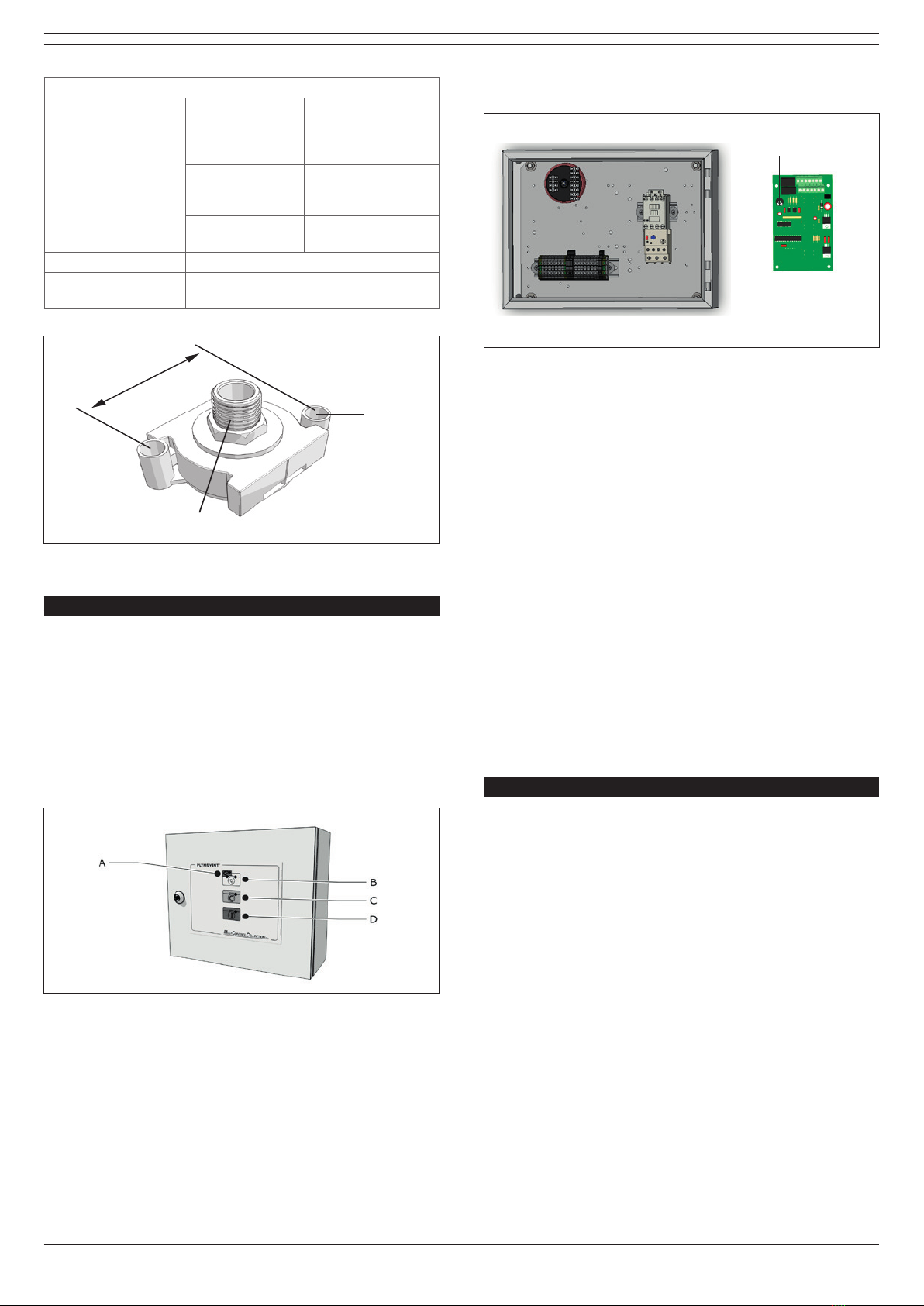
- PCU-1000/7500 control box
- door key
The control unit is delivered complete with functions for
manual and automatic start/stop of the exhaust fan.
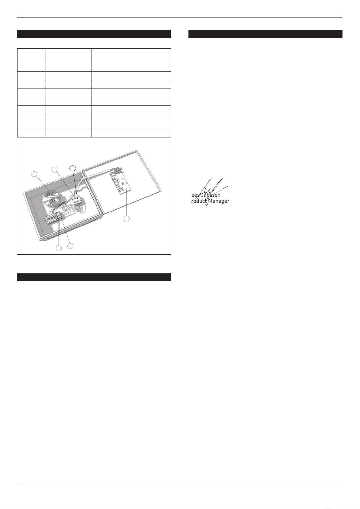
4.2 Electric connection
• Connect the PCU-1000/7500 in accordance with the
separately supplied electrical diagram.
CAUTION
Electric connection to be executed in accordance
with local requirements. Ensure compliance with the
EMC regulatory arrangements.
CAUTION
Make sure the machine is suitable for connection to
the local mains. Information about the connection
voltage and frequency can be found on the
identication plate.
5 MAINTENANCE
The PCU-1000/7500 requires no specic maintenance.
6 TROUBLESHOOTING
If the PCU-1000/7500 does not function (correctly), please
contact your supplier.