MultiSmart®Arm/ENG/USA/CAN/6/16
Energy Saver
For automatic start/stop of fan. Adjustable overrun
period of between 7 sec. to 6 min. Incl. inductive sensor
with 5 m, (16 ft) cable. Built-in contactor
must be fitted with relevant fan-motor overload
(not included). Power supply: 3~¨230/400 V*.
Prod. no ES-90-005 incl. 75 VA/24 V
transformer for hood light.
Prod. no ES-90-006 incl. 75 VA/24 V
transformer. For two arms with lights.
Complementary products and accessories
Fan Airflow
Freeblowing
m3/h, CFM
Motor
kW V
(50Hz)
1300, 765
1300, 765
1800, 1059
2100, 1236
2100, 1236
3000, 1766
4700, 2766
6000, 3532
1300
1301
1800
2100
2101
3000
4700
6000
0,37 kW 3~ 400 V*
0,37 kW 1~ 230 V*
0,55 kW 3~ 400 V*
0,75 kW 3~ 400 V*
0,75 kW 1~ 230 V*
1,10 kW 3~ 400 V*
2,20 kW 3~ 400 V*
4,00 kW 3~400 V*
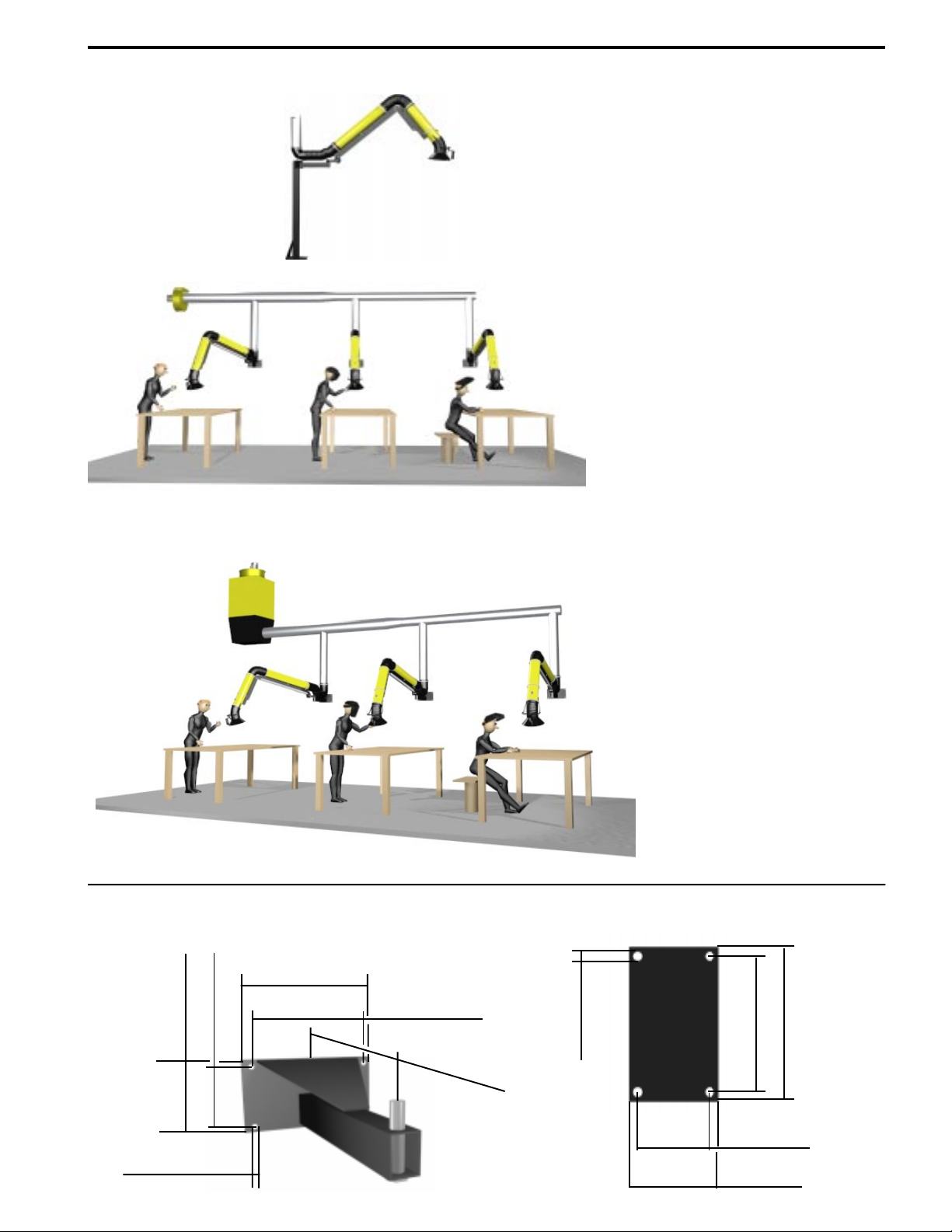
Stanchion
Accessory for ceiling, floor or wall mounting
of MultiSmart®Arm.
Length: 110 cm, 3.6 ft. Prod. no PA-110
Length: 220 cm, 7.2 ft. Prod. no PA-220
SmartArm Extention kit
Contains all neccesseary items to convert a 3
meter, (10 ft) arm to a 4 meter, (14 ft) arm.
Prod. no SAE-125-4
Prod. no SAE-160-4
Prod. no SAE-200-4
Transformer
230 V* – 24V/75 VA transformer for
halogen lamp cartridge HL-20/24.
Prod. no TR-24/75
Fully automatic damper
Fully automatic motordriven damper for fitting
to Ø 160 mm, 6" Ø duct. Adjustable overrun
period between 7 sec. and 6 min., to
capture after-fume. Inductive sensor
with 5 m (16 ft) of cable is included
as standard. Power supply: 1~ 230 V*.
Can be complemented with switch
assembly (S-100) for manual
control.
Prod. no ASE-12
Control unit
For automatic start/stop of a central fan in
a system with several extractors. To be used in
conjuction with the Energy Saver or Automatic
Damper. Power supply: 3~ 230/400 V*.
Prod. no M-1000
Fans FS and FA
Available in many sizes with free blowing air volumes
from 1300 m3/h, 765 CFM to 6000 m3/h,3532 CFM. A
unique anti-spark impeller made from aluminium gives
maximum security.
NOTE! ALL FANS MUST BE FITTED
WITH RELEVANT MOTOR OVERLOAD
PROTECTION (NOT INCLUDED).
Starter
For manual start/stop of the fan via a switch in
the hood. Complete with switch assembly and
10 m, (33 ft) cable. Built-in contactor must be fitted
with relevant fan motor overload (not included).
Power supply: 3~ 230/400 V*.
Prod. no SA-24/75 incl. 75 VA/24 V
transformer for halogene lamp on one workstation.
Prod. no SA-24/75-2 incl. 75 VA/24 V transformer
for two halogene lamps on two workstations.
Halogen lamp cartridge
To be fitted in the hood. Consists of 20W/
24 V halogen lap, switch assembly and
10 m, (33 ft) cable. Must be complemented
with transformer TR-24 or Starter SA-24.
Prod. no HL-20/24-125
Prod. no HL-20/24-160
Prod. no HL-20/24-200
Switch assembly
Switch assembly with 10 m(10 ft) cable for manual
operation from the hood of fan and light. Also
supplied as standard as part of ES-90 and ASE-12.
Inkl.
Prod. no S-100
Damper kit
Contains all necceseary items to
install a ratchet damper for fine
tuning the airflow through the arm.
Prod. no D-125
Prod. no D-160
Prod. no D-200
* Other voltages and frequences for motors are available.
* Other voltages are available
* Other voltages are available
* Other voltages are available
* Other voltages are available
* Other voltages are available
FS
* Is not available in MSAS
* Not available in MSAS